These pages provides a comprehensive guide to the hardware-accelerated switching capabilities of NVIDIA® BlueField® and NVIDIA® ConnectX® platforms, including configurations for switchdev mode, representor models, and network features such as vDPA, bridge offload, and link aggregation.
Introduction
BlueField and ConnectX networking platforms leverage hardware-based switching offloads to deliver high-performance network virtualization with minimal CPU overhead. By offloading complex switching logic to the E-Switch, these platforms ensure unparalleled scalability and efficiency for modern data center workloads.
This section details the switching capabilities enabled by DOCA, providing the foundational knowledge and configuration steps required to manage virtualized network resources. The following chapters guide users through the DPU kernel representor model, hardware-accelerated vDPA, and bridge offloading techniques. Additionally, it covers essential network management tasks, including the implementation of link aggregation (LAG) and the configuration of host PF/VF parameters and uplink MTU settings.
Switch Device Mode
Switchdev mode allows the physical function (PF) to operate as a virtual switch, granting software a means to control associated virtual function (VF) and scalable function (SF) traffic. In this mode, software can intercept incoming/outgoing VF/SF traffic and configure steering rules that offload traffic.
Once this mode is configured, the PF is considered an E-Switch, and additional ports are allocated for each associated VF and SF. The additional ports are referred to as port representors.
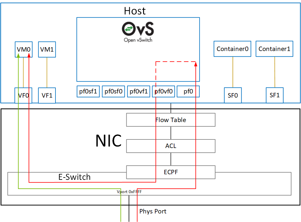
ConnectX and BlueField NIC Mode
Switchdev mode may be configured for each PF as described in the "DOCA Switching | Configuring Switchdev Mode" section.
BlueField DPU Mode
When BlueField operates in DPU mode, switchdev mode is configured by default for all PFs on the Arm. That configuration must not be changed. In this mode, the host cannot configure PFs to operate in switchdev mode. Instead, host PFs operate in legacy mode only.
The following diagram shows the mapping of between the PCIe functions exposed on the host side and the representors. For the sake of simplicity, the diagram shows a single port model (duplicated for the second port).
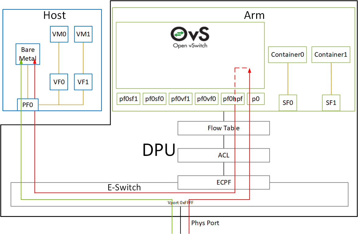
The red arrow demonstrates packet flow through the representors, while the green arrow demonstrates the packet flow when steering rules are offloaded to the embedded switch.
E-Switch Port
Once switchdev mode is configured, the PF acts as an e-switch and manages all switch ports. The e-switch can be used to control VF and SF traffic. Software can then use the e-switch through the netdev and RDMA core interfaces.
Netdev Interface
The e-switch has a netdev interface (e.g., pf0), allowing it to be used with common Linux networking tools (e.g., ifconfig) and OVS. While the interface looks like a regular network port, in reality it is considered the upstream representor and it cannot host an IP server. That is, configuring an IP address to this interface is not useful (e.g., it cannot be pinged).
The netdev interface can be used mainly by OVS and the Linux bridge.
To overcome this limitation, it is possible to create SFs. For more details, see BlueField Scalable Functions.
RDMA Core Interface
The e-switch has an RDMA device instance (e.g., mlx5_0) which grants software access to the e-switch capabilities for offloading steering rules and accessing various RDMA capabilities.
The instance behaves like an RDMA core device with the following limitations:
-
It cannot host an RDMA connection and cannot be used to connect to the remote RDMA target (e.g., cannot do RDMA send)
-
It cannot have an RDMA GID
The RDMA device can mainly be used to configure the e-switch.
To overcome this limitation, it is possible to create SFs. For more details, see BlueField Scalable Functions.
Representor Port
For each network function (i.e., VF/SF) a corresponding representor port is created. The representor port represents the actual port. The network function can then be used to access the network by a VM/container, while the representor can be used to manage switching by virtual switch software (e.g., bare metal host).
Netdev Interface
Each representor port would have a netdev interface (e.g., pf0vf0), allowing it to be used with common Linux networking tools (e.g., ifconfig) as well as OVS.
While the interface looks like a regular network port, in reality it is a VF/SF representor and it cannot host an IP server. That is, configuring an IP address to this interface is not useful (e.g., it cannot be pinged).
The representor netdev can be used to refer to a specific network function when configuring steering rules using OVS or Linux bridge.
RDMA Core Interface
The representor does not have a corresponding RDMA core instance (e.g., mlx5_0). Instead, it is managed by the RDMA core instance of the e-switch manager. Each representor is an RDMA port of the e-switch RDMA device.
Configuring Switchdev Mode
For BlueField in DPU mode, there is no need to follow these steps as the PFs are already configured to switchdev mode by default.
-
Unbind all VFs:
# echo 0000:3d:00.2 > /sys/bus/pci/drivers/mlx5_core/unbind
# echo 0000:3d:00.3 > /sys/bus/pci/drivers/mlx5_core/unbind
VMs with attached VFs must be powered off to be able to unbind the VFs.
-
Change the e-switch mode from legacy to switchdev on the PF device:
# devlink dev eswitch set pci/0000:3d:00.0 mode switchdevThis creates the VF/SF representor ports in the host OS.
Before changing the mode, make sure that all VFs are unbound.
To return to legacy mode, run:
# devlink dev eswitch set pci/0000:3d:00.0 mode legacyThis removes the VF/SF representor ports.
On OSes or kernels that do not support devlink, moving to switchdev mode can be done using sysfs:
# echo switchdev > /sys/class/net/pf0/compat/devlink/mode
-
At this stage, VF representors have been created. To map a representor to its VF, make sure to obtain the representor's
switchidandportnameby running:# ip -d link show eth0 41: eth0: <BROADCAST,MULTICAST,UP,LOWER_UP> mtu 1500 qdisc mq state UP mode DEFAULT group default qlen 1000 link/ether ba:e6:21:37:bc:d4 brd ff:ff:ff:ff:ff:ff promiscuity 0 addrgenmode eui64 numtxqueues 10 numrxqueues 10 gso_max_size 65536 gso_max_segs 65535 portname pf0vf0 switchid f4ab580003a1420cWhere:
-
switchid– used to map representor to device, both device PFs have the sameswitchid -
portname– used to map representor to PF and VF. Value returned ispf<X>vf<Y>, whereXis the PF number andYis the number of VF.
-
-
Bind the VFs:
echo 0000:3d:00.2 > /sys/bus/pci/drivers/mlx5_core/bind
echo 0000:3d:00.3 > /sys/bus/pci/drivers/mlx5_core/bind
Last updated: