RPC Log History
RPC log history (enabled by default) records all the RPC requests (from snap_rpc.py and spdk_rpc.py) sent to the SNAP application and the RPC response for each RPC requests in a dedicated log file, /var/log/snap-log/rpc-log. This file is visible outside the container (i.e., the log file's path on the DPU is /var/log/snap-log/rpc-log as well).
The SNAP_RPC_LOG_ENABLE env can be used to enable (1) or disable (0) this feature.
RPC log history is supported with SPDK version spdk23.01.2-12 and above.
When RPC log history is enabled, the SNAP application writes (in append mode) RPC request and response message to /var/log/snap-log/rpc-log constantly. Pay attention to the size of this file. If it gets too large, delete the file on the DPU before launching the SNAP pod.
SR-IOV
SR-IOV configuration depends on the kernel version and must be handled carefully to ensure device visibility and system stability across both hypervisor and DPU orchestrators.
To ensure a safe and stable SR-IOV setup, follow these steps:
-
Preconfigure VF controllers on the DPU – Before configuring SR-IOV on the host, ensure that the DPU is properly configured with all required VF controllers already created and opened.
-
VF functions are always visible and configurable on the DPU side. Use the following command to verify:
snap_rpc.py emulation_function_list --all
-
Confirm that the configuration meets your requirements.Check the number of resources allocated for the PF, specifically MSIX and queues (queried using snap_rpc.py virtio_blk_controller_list RPC output, field free_queues and free_msix ) are enough to satisfy your needs for all underlying VFs.Use dynamic MSIX if needed and supported.
-
Once host-side configuration begins, further modifications may not be possible.
-
-
Disable autoprobing with
sriov_drivers_autoprobe=0– In deployments with many virtual devices, autoprobing must be disabled to ensure stable device discovery. Failing to disable autoprobing may result in:Incomplete device visibilityMissing virtual disksSystem hangs during initializationUnreliable behavior in large-scale environments (more than 100 VFs)Recommended configuration for large-scale deployments:Disable autoprobe: echo 0 > /sys/bus/pci/devices/<BDF>/sriov_drivers_autoprobe Manually bind the VFs to drivers using tools such as driverctl, or by writing to bind/unbind in sysfs. -
Configure SR-IOV on the host – For small-scale deployments (fewer than 100 VFs), use the
sriov_totalvfsentry:For newer drivers, use:echo <number_of_vfs> > /sys/bus/pci/devices/<BDF>/sriov_totalvfs
echo <number_of_vfs> > /sys/bus/pci/devices/<BDF>/sriov_numvfs
After SR-IOV configuration, no disks appear in the hypervisor by default. Disks are only visible inside VMs once the corresponding PCIe VF is assigned to the VM via a virtualization manager (e.g., libvirt, VMware). To use the device directly from the hypervisor, manually bind the VF to the appropriate driver.
Additional notes:
-
Hot-plugged PFs do not support SR-IOV.
-
For deployments requiring more than 127 VFs, add the following kernel parameter to the host’s boot command line:
Without this, the host may log errors such as:pci=assign-busses
These errors prevent the virtio driver from probing the device.pci 0000:84:00.0: [1af4:1041] type 7f class 0xffffff pci 0000:84:00.0: unknown header type 7f, ignoring device
Hot-pluggable PCIe Functions
PCI hotplug functions allow the addition or removal of PCI devices from a running system without requiring a machine shutdown or interrupting operations. This technology relies on hardware and software support to isolate individual slots, manage power and control signals, and ensure proper power sequencing during device insertion or removal. When a device is hotplugged, the operating system's hotplug service handles quiescing the device driver, controlling the physical slot, and managing power states while the bus remains active.
SNAP enables dynamic hot-plugging and hot-unplugging of PCIe functions at runtime via dedicated RPCs (see section "SNAP-4 Service Advanced Features | Hot pluggable PCIe Functions Management"). Once a PCIe function is hotplugged, it persists in the host's PCIe device list until it is explicitly unplugged via RPC or a firmware reset occurs. This persistence is maintained even if the SNAP process terminates.
Two-step PCIe Hotplug
The two-step PCIe hotplug method divides the process into two distinct phases:
-
PCIe function creation (the function is accessible within the DPU application but remains hidden from the host OS/kernel).
-
PCIe function exposure to the host.
Symmetrically, hot-unplugging involves hiding the function from the host before destroying it.
A primary advantage of this approach is the ability to pre-configure a controller on the function prior to exposing it to the host driver. Users are required to create a controller to initiate the host exposure phase.
Sync vs. Async Hotplug Operations
Exposing a new PCIe function involves notifying the host and awaiting its response. SNAP provides two modes for this operation, controlled via the --wait_for_done option:
-
Synchronized hotplug – The RPC blocks until the host acknowledges the action and updates its PCIe function list, or until the host is determined to be temporarily unavailable.
-
Asynchronized hotplug – The RPC does not block. The user must actively validate the function's hotplug state using the
emulation_functions_listRPC to check for host acceptance.
Synchronized operations (using --wait_for_done) are recommended for single hotplug/unplug actions. For multiple operations, it is more time-efficient to execute all actions asynchronously (without --wait_for_done) and then validate their status altogether with a single emulation_functions_list RPC call.
Host Awareness
During periods such as OS reboots, the host may temporarily be unable to accept new PCIe functions. SNAP offers two modes to handle these scenarios, configurable via the --mode parameter:
-
Host-aware mode (recommended) – The device checks the host's state and takes it into consideration. If the host is unready, the firmware blocks the command and returns an RPC error. Users must manually retry the operation if a failure occurs.
-
Host-unaware mode – The operation proceeds regardless of the host's state. The user is responsible for ensuring the PCI enumeration process completes successfully and avoiding undesired behaviors, as the firmware will not block the command.
Attention Button
Because the Linux Virtio PCI driver stack does not support the surprise removal of devices, ungraceful removal can cause the host PCI subsystem to repeatedly attempt device recovery (like resetting the device and reprogramming MSI-X vectors) even after it is gone.
The Attention Button feature, defined in the PCIe specification, enables a graceful hot-plug/hot-unplug sequence. When utilized via the host_aware_ab mode, all state transitions are intentionally delayed by 5 seconds to allow the host OS time to react to the corresponding PCIe events.
Issuing a hot-unplug RPC immediately after an async hotplug RPC without --wait_for_done (or vice versa) using the host_aware_ab mode will cause the second RPC to return a failure. However, this failure will not affect the results of the initial RPC
Legacy ("One-step") PCIe Hotplug
The deprecated legacy mechanism uses a single-step "create-and-expose" flow where the emulation function is instantiated on the DPU and immediately presented to the host in one RPC. This tight coupling means the function's lifecycle is directly bound to host enumeration without any intermediate hidden state.
This legacy approach has several structural limitations:
-
The controller cannot be fully configured, tested, and bound to backing storage before being exposed to the host.
-
Failures in host enumeration translate directly into RPC failures or undefined host behavior, as the operation cannot be retried on a hidden function.
-
Functions cannot be hidden from the host for maintenance, migration, or gradual rollout while keeping the emulation object alive.
-
It lacks options for selecting advanced host-awareness settings or the Attention Button flow.
Zero Copy (SNAP-direct)
Zero-copy is supported on SPDK 21.07 and higher.
SNAP-direct allows SNAP applications to transfer data directly from the host memory to remote storage without using any staging buffer inside the DPU.
SNAP enables the feature according to the SPDK BDEV configuration only when working against an SPDK NVMe-oF RDMA block device.
To enable zero copy, set the environment variable (as it is enabled by default):
SNAP_RDMA_ZCOPY_ENABLE=1
For more info refer to SNAP-4 Service Environment Variables.
NVMe/TCP XLIO Zero Copy
NVMe/TCP Zero Copy is implemented as a custom NVDA_TCP transport in SPDK NVMe initiator, and it is based on a new XLIO socket layer implementation.
The implementation is different for Tx and Rx:
-
The NVMe/TCP Tx Zero Copy is similar between RDMA and TCP in that the data is sent from the host memory directly to the wire without an intermediate copy to Arm memory
-
The NVMe/TCP Rx Zero Copy allows achieving partial zero copy on the Rx flow by eliminating copy from socket buffers (XLIO) to application buffers (SNAP). But data still must be DMA'ed from Arm to host memory.
To enable NVMe/TCP Zero Copy, use SPDK v22.05.nvda --with-xlio (v22.05.nvda or higher).
For more information about XLIO including limitations and bug fixes, refer to the NVIDIA Accelerated IO (XLIO) Documentation.
To enable SNAP TCP XLIO Zero Copy:
-
SNAP container: Set the environment variables and resources in the YAML file to request 6G of hugepages:
resources:
  requests:
    memory: "4Gi"
    cpu: "8"
  limits:
    hugepages-2Mi: "6Gi"
    memory: "6Gi"
    cpu: "16"

## Set according to the local setup
env:
  - name: APP_ARGS
    value: "--wait-for-rpc"
  - name: SPDK_XLIO_PATH
    value: "/usr/lib/libxlio.so"
-
SNAP sources: Set the environment variables and resources in the relevant scripts
-
In
run_snap.sh, edit theAPP_ARGSvariable to use the SPDK command line argument--wait-for-rpc:APP_ARGS="--wait-for-rpc"
-
In
set_environment_variables.sh, uncomment theSPDK_XLIO_PATHenvironment variable:export SPDK_XLIO_PATH="/usr/lib/libxlio.so"
-
NVMe/TCP XLIO requires a BlueField Arm OS hugepage size of 4Gi. For information on configuring the hugepages, refer to sections "Step 1: Allocate Hugepages" and "Adjusting YAML Configuration".
At high scale, it is required to use the global variable XLIO_RX_BUFS=4096 even though it leads to high memory consumption. Using XLIO_RX_BUFS=1024 requires lower memory consumption but limits the ability to scale the workload.
For more info refer to SNAP-4 Service Environment Variables.
It is recommended to configure NVMe/TCP XLIO with the transport ack timeout option increased to 12.
[dpu] spdk_rpc.py bdev_nvme_set_options --transport-ack-timeout 12
Other bdev_nvme options may be adjusted according to requirements.
Expose an NVMe-oF subsystem with one namespace by using a TCP transport type on the remote SPDK target.
[dpu] spdk_rpc.py sock_set_default_impl -i xlio
[dpu] spdk_rpc.py framework_start_init
[dpu] spdk_rpc.py bdev_nvme_set_options --transport-ack-timeout 12
[dpu] spdk_rpc.py bdev_nvme_attach_controller -b nvme0 -t nvda_tcp -a 3.3.3.3 -f ipv4 -s 4420 -n nqn.2023-01.io.nvmet
[dpu] snap_rpc.py nvme_subsystem_create --nqn nqn.2023-01.com.nvda:nvme:0
[dpu] snap_rpc.py nvme_namespace_create -b nvme0n1 -n 1 --nqn nqn. 2023-01.com.nvda:nvme:0 --uuid 16dab065-ddc9-8a7a-108e-9a489254a839
[dpu] snap_rpc.py nvme_controller_create --nqn nqn.2023-01.com.nvda:nvme:0 --ctrl NVMeCtrl1 --pf_id 0 --suspended --num_queues 16
[dpu] snap_rpc.py nvme_controller_attach_ns -c NVMeCtrl1 -n 1
[dpu] snap_rpc.py nvme_controller_resume -c NVMeCtrl1 -n 1

[host] modprobe -v nvme
[host] fio --filename /dev/nvme0n1 --rw randrw --name=test-randrw --ioengine=libaio --iodepth=64 --bs=4k --direct=1 --numjobs=1 --runtime=63 --time_based --group_reporting --verify=md5
For more information on XLIO, please refer to XLIO documentation.
Encryption
The SPDK version included with SNAP supports hardware encryption/decryption offload. To enable AES/XTS and allow the mlx5_2 and mlx5_3 SFs to support encryption, they must be designated as trusted.
-
Edit the configuration file
/etc/mellanox/mlnx-sf.conf. -
Append the following commands to configure the
VHCA_TRUST_LEVELand create the SFs:/usr/bin/mlxreg -d 03:00.0 –-reg_name VHCA_TRUST_LEVEL –-yes –-indexes "vhca_id=0x0,all_vhca=0x1" –-set "trust_level=0x1" /usr/bin/mlxreg -d 03:00.1 --reg_name VHCA_TRUST_LEVEL --yes --indexes "vhca_id=0x0,all_vhca=0x1" --set "trust_level=0x1" /sbin/mlnx-sf –action create -–device 0000:03:00.0 -–sfnum 0 --hwaddr 02:11:3c:13:ad:82 /sbin/mlnx-sf –action create -–device 0000:03:00.1 -–sfnum 0 --hwaddr 02:76:78:b9:6f:52
-
Reboot the DPU to apply these changes.
Zero Copy (SNAP-direct) with Encryption
SNAP offers support for zero copy with encryption for bdev_nvme with an RDMA transport.
If another bdev_nvme transport or base bdev other than NVMe is used, then zero copy flow is not supported, and additional DMA operations from the host to the BlueField Arm are performed.
Refer to section "SNAP-4 Service Advanced Features | SPDK Crypto Example" to see how to configure zero copy flow with AES_XTS offload.
|
Command |
Description |
|---|---|
|
|
Accepts a list of devices to be used for the crypto operation |
|
|
Creates a crypto key |
|
|
Constructs NVMe block device |
|
|
Creates a virtual block device which encrypts write IO commands and decrypts read IO commands |
mlx5_scan_accel_module
Accepts a list of devices to use for the crypto operation provided in the --allowed-devs parameter. If no devices are specified, then the first device which supports encryption is used.
For best performance, it is recommended to use the devices with the largest InfiniBand MTU (4096). The MTU size can be verified using the ibv_devinfo command (look for the max and active MTU fields). Normally, the mlx5_2 device is expected to have an MTU of 4096 and should be used as an allowed crypto device.
Command parameters:
|
Parameter |
Mandatory? |
Type |
Description |
|---|---|---|---|
|
|
No |
Number |
QP size |
|
|
No |
Number |
Size of the shared requests pool |
|
|
No |
String |
Comma-separated list of allowed device names (e.g., "mlx5_2") Make sure that the device used for RDMA traffic is selected to support zero copy. |
|
|
No |
Boolean |
Enables accel_mlx5 platform driver. Allows AES_XTS RDMA zero copy. |
accel_crypto_key_create
Creates crypto key. One key can be shared by multiple bdevs.
Command parameters:
|
Parameter |
Mandatory? |
Type |
Description |
|---|---|---|---|
|
|
Yes |
Number |
Crypto protocol (AES_XTS) |
|
|
Yes |
Number |
Key |
|
|
Yes |
Number |
Key2 |
|
|
Yes |
String |
Key name |
bdev_nvme_attach_controller
Creates NVMe block device.
Command parameters:
|
Parameter |
Mandatory? |
Type |
Description |
|---|---|---|---|
|
|
Yes |
String |
Name of the NVMe controller, prefix for each bdev name |
|
|
Yes |
String |
NVMe-oF target trtype (e.g., rdma, pcie) |
|
|
Yes |
String |
NVMe-oF target address (e.g., an IP address or BDF) |
|
|
No |
String |
NVMe-oF target trsvcid (e.g., a port number) |
|
|
No |
String |
NVMe-oF target adrfam (e.g., ipv4, ipv6) |
|
|
No |
String |
NVMe-oF target subnqn |
bdev_crypto_create
This RPC creates a virtual crypto block device which adds encryption to the base block device.
Command parameters:
|
Parameter |
Mandatory? |
Type |
Description |
|---|---|---|---|
|
|
Yes |
String |
Name of the base bdev |
|
|
Yes |
String |
Crypto bdev name |
|
|
Yes |
String |
Name of the crypto key created with |
SPDK Crypto Example
The following is an example of a configuration with a crypto virtual block device created on top of bdev_nvme with RDMA transport and zero copy support:
[dpu] # spdk_rpc.py mlx5_scan_accel_module --allowed-devs "mlx5_2" --enable-driver
[dpu] # spdk_rpc.py framework_start_init
[dpu] # spdk_rpc.py accel_crypto_key_create -c AES_XTS -k 00112233445566778899001122334455 -e 11223344556677889900112233445500 -n test_dek
[dpu] # spdk_rpc.py bdev_nvme_attach_controller -b nvme0 -t rdma -a 1.1.1.1 -f ipv4 -s 4420 -n nqn.2016-06.io.spdk:cnode0
[dpu] # spdk_rpc.py bdev_crypto_create nvme0n1 crypto_0 -n test_dek
[dpu] # snap_rpc.py nvme_subsystem_create --nqn nqn.2023-05.io.nvda.nvme:0
[dpu] # snap_rpc.py nvme_controller_create --nqn nqn.2023-05.io.nvda.nvme:0 --pf_id 0 --ctrl NVMeCtrl0 --suspended
[dpu] # snap_rpc.py nvme_namespace_create –nqn nqn.2023-05.io.nvda.nvme:0 --bdev_name crypto_0 –-nsid 1 -–uuid 263826ad-19a3-4feb-bc25-4bc81ee7749e
[dpu] # snap_rpc.py nvme_controller_attach_ns –-ctrl NVMeCtrl0 --nsid 1
[dpu] # snap_rpc.py nvme_controller_resume –-ctrl NVMeCtrl0
Virtio-blk Live Migration
Live migration is a standard process supported by QEMU which allows system administrators to pass devices between virtual machines in a live running system. For more information, refer to QEMU VFIO Device Migration documentation.
Live migration is supported for SNAP virtio-blk devices in legacy and standard VFIO modes. Legacy mode uses drivers like NVIDIA's proprietary vDPA-based Live Migration Solution, while standard mode leverages the latest kernel capabilities using the virtio-vfio-pci kernel driver. Legacy mode can be enabled/disabled using the environment variable `VIRTIO_CTRL_VDPA_ADMIN_Q` (enabled by default).
In the standard virtio live migration process, the device is expected to complete all inflight I/Os, with no configurable timeout. If the remote storage is unavailable (disconnected or non-responsive), the device migration will wait indefinitely. This means migration time cannot be guaranteed, representing a degradation compared to the functionality of legacy mode.
Software Requirements for Standard VFIO
-
Kernel – 6.16-rc3+ (using
virtio-vfio-pcidriver) -
QEMU – 9.2+
-
libvirt – 10.6+
SNAP Configuration
-
Set the environment variable
VIRTIO_CTRL_VDPA_ADMIN_Qto 1 (default) for legacy or 0 for standard VFIO mode. -
Create a PF Controller with Admin Queue (common to both modes):
snap_rpc.py virtio_blk_controller_create --admin_q …
SNAP Container Live Upgrade
The Live Upgrade feature enables administrators to update a container's SNAP image without incurring system downtime.
Although newer releases may introduce features that alter system behavior, the upgrade architecture is engineered to maintain full backward and forward compatibility.
Before initiating an upgrade, consult the "Changes and New Features" section of the SNAP-4 Service Release Notes to verify the explicitly supported upgrade paths and compatibility matrices for your current version.
Live Upgrade Prerequisites
To enable live upgrade, perform the following modifications:
-
Allocate double hugepages for the destination and source containers.
-
Make sure the requested amount of CPU cores is available.
The default YAML configuration sets the container to request a CPU core range of 8-16. This means that the container is not deployed if there are fewer than 8 available cores, and if there are 16 free cores, the container utilizes all 16.
For instance, if a container is currently using all 16 cores and, during a live upgrade, an additional SNAP container is deployed. In this case, each container uses 8 cores during the upgrade process. Once the source container is terminated, the destination container starts utilizing all 16 cores.
For 8-core DPUs, the
.yamlmust be edited to the range of 4-8 CPU cores. -
Change the name of the
doca_snap.yamlfile that describes the destination container (e.g.,doca_snap_new.yaml) so as to not overwrite the running container.yaml. -
Change the name of the new
.yamlpod and container on lines 16 and 20, respectively (e.g.,snap-new). -
Deploy the the destination container by copying the new yaml (e.g.,
doca_snap_new.yaml) to kubelet.
After deploying the destination container, until the live update process is complete, avoid making any configuration changes via RPC. Specifically, do not create or destroy hotplug functions.
Live updates are exclusively supported between consecutive software releases. Skipping versions during a live update process is not supported and may result in system failure.
When restoring a controller in the destination container during a live update, it is recommended to use the same arguments originally used for controller creation in the source container.
User may need to update the RPC alias since the new container name has been edited.
Performing a live update disables the ML Optimizer Online service in the source container. The service in the destination container remains unaffected and operates normally.
Official support for the live_update.py script is strictly limited to the following SPDK block devices: NVMe-oF/RDMA, Null, Malloc, AIO and Delay bdev. Although users can technically extend the script logic to accommodate other block devices, NVIDIA does not officially validate or support such configurations.
SNAP Container Live Upgrade Procedure
-
Follow the steps in section "SNAP-4 Service Advanced Features | Live Upgrade Prerequisites" and deploy the destination SNAP container using the modified
yamlfile. -
Query the source and destination containers:
crictl ps -r -
Check for
SNAP started successfullyin the logs of the destination container, then copy the live update from the container to your environment.[dpu] crictl logs -f <dest-container-id> [dpu] crictl exec <dest-container-id> cp /opt/nvidia/nvda_snap/bin/live_update.py /etc/nvda_snap/ -
Run the
live_update.pyscript to move all active objects from the source container to the destination container:[dpu] cd /etc/nvda_snap [dpu] ./live_update.py -s <source-container-id> -d <dest-container-id>Transition freely between a SNAP source package service and a SNAP container service in either direction.
-
Use the
-s 0flag to specify that the original process (source) is running from the SNAP source package. -
The tool does not support transitioning directly from one SNAP source package service to another
Customize the suspend timeout by passing the
-tor--timeoutparameter (e.g.,-t 1sets the timeout to 1 ms). The system defaults to 20 ms. -
-
After the script completes, the live update process also completes, delete the source container by removing the YAML from kubelet tool:
To post RPCs, use the
crictltool:crictl exec -it <container-id X> snap_rpc.py <RPC-method> crictl exec -it <container-id Y> spdk_rpc.py <RPC-method>To automate the SNAP configuration (e.g., following failure or reboot) as explained in section "Automate SNAP Configuration (Optional)",
spdk_rpc_init.confandsnap_rpc_init.confmust not include any configs as part of the live upgrade. Then, once the transition to the new container is done,spdk_rpc_init.confandsnap_rpc_init.confcan be modified with the desired configuration.
SNAP Container Live Upgrade Commands
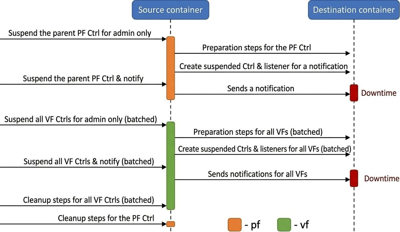
The live upgrade process allows you to move SNAP controllers and SPDK block devices between containers while minimizing host VM disruption. PFs are live-updated individually, while all VFs are batched together to reduce total downtime.
The upgrade is executed using a dedicated live update tool, which handles PF controllers sequentially and then processes all VF controllers in batched phases.
PF Live Update (Sequential, per PF)
-
Suspend controller (admin only): On the source container, suspend the controller in admin-only mode. This ensures the controller stops processing admin commands from the host driver, avoiding state changes during the handover. I/O traffic continues, meaning downtime has not yet started.
NVMe example:NMVe exmaple: snap_rpc.py nvme_controller_suspend --ctrl NVMeCtrl0VF0 --admin_only Virtio-blk example:Virtio-blk Example snap_rpc.py virtio_blk_controller_suspend --ctrl VBLKCtrl0 --events_only -
Prepare destination container: On the destination container, create all required objects for the new controller, including attaching the backend device.
NVMe example:NMVe exmaple: spdk_rpc.py bdev_nvme_attach_controller ... snap_rpc.py nvme_subsystem_create ... snap_rpc.py nvme_namespace_create -n 1 ... Virtio-blk example:Virtio-blk Example spdk_rpc.py bdev_nvme_attach_controller ... -
Create suspended controller (as listener): On the destination container, create the controller in a suspended state and designate it as a listener for a live update notification from the source container. The controller in the source container is still handling I/O, meaning downtime has not yet started.
NVMe example:NMVe exmaple: snap_rpc.py nvme_controller_create --pf_id 0 --vf_id 0 --ctrl NVMeCtrl0VF0 --live_update_listener --suspended ... snap_rpc.py nvme_controller_attach_ns -c NVMeCtrl0VF0 -n 1 Virtio-blk example:Virtio-blk Example snap_rpc.py virtio_blk_controller_create --pf_id 0 --vf_id 0 --ctrl VBLKCtrl0VF0 --suspended --live_update_listener ... -
Suspend and notify: On the source container, suspend the controller using the
--live_update_notifierflag. This triggers the start of downtime and sends a notification to the destination container. Once suspended, the controller on the destination container resumes and starts handling I/O, marking the end of downtime.-
NVMe example:
snap_rpc.py nvme_controller_suspend --ctrl NVMeCtrl0VF0 --live_update_notifier --timeout_ms 20
-
Virtio-blk example:
snap_rpc.py virtio_blk_controller_suspend --ctrl VBLKCtrl0 -t 20 -lu
-
-
Cleanup source PF: The PF controller on the source is destroyed only after all of its related VFs have been migrated and cleaned up.
The PF controller must remain present in the source container until all related VFs have been successfully removed.
VF Live Update (Batched, All VFs Together)
After each PF is live-updated, all active VFs are collected and processed together in batched phases.
-
NVMe only – Prepare destination for all NVMe VFs (batched): On the destination container, create all required bdevs, subsystems, and namespaces.
NVMe example:NMVe exmaple: spdk_rpc.py bdev_nvme_attach_controller ... # for VF0 spdk_rpc.py bdev_nvme_attach_controller ... # for VF1 snap_rpc.py nvme_subsystem_create ... # for VF0 snap_rpc.py nvme_namespace_create ... # for VF0 snap_rpc.py nvme_subsystem_create ... # for VF1 snap_rpc.py nvme_namespace_create ... # for VF1 ... -
Suspend all VF controllers on source (admin only): On the source container, suspend all VF controllers using a single batched command. I/O traffic continues for all VFs at this point, meaning downtime has not yet started.
NVMe example:NMVe exmaple: snap_rpc.py nvme_controller_suspend --ctrl NVMeCtrl0VF0 --admin_only snap_rpc.py nvme_controller_suspend --ctrl NVMeCtrl0VF1 --admin_only ... Virtio-blk example:Virtio-blk Example snap_rpc.py virtio_blk_controller_suspend --ctrl VBLKCtrl0VF0 --events_only snap_rpc.py virtio_blk_controller_suspend --ctrl VBLKCtrl0VF1 --events_only ... -
Prepare destination for all VFs (batched): On the destination container, create all required backend devices (for virtio-blk) and controllers (suspended, with live update listener) for every VF using a single batched command.
NVMe example:NMVe exmaple: snap_rpc.py nvme_controller_create --pf_id 0 --vf_id 0 --ctrl NVMeCtrl0VF0 --live_update_listener --suspended ... snap_rpc.py nvme_controller_create --pf_id 0 --vf_id 1 --ctrl NVMeCtrl0VF1 --live_update_listener --suspended ... ... Virtio-blk example:Virtio-blk Example spdk_rpc.py bdev_nvme_attach_controller ... # for VF0 spdk_rpc.py bdev_nvme_attach_controller ... # for VF1 snap_rpc.py virtio_blk_controller_create --pf_id 0 --vf_id 0 --ctrl VBLKCtrl0VF0 --suspended --live_update_listener ... snap_rpc.py virtio_blk_controller_create --pf_id 0 --vf_id 1 --ctrl VBLKCtrl0VF1 --suspended --live_update_listener ... ... -
Suspend and notify all VFs (batched): On the source container, suspend all VF controllers with the live update notifier flag using a single batched command. This initiates downtime for all VFs. The destination controllers receive the notifications and resume handling I/O, marking the end of downtime.
NVMe example:NMVe exmaple: snap_rpc.py nvme_controller_suspend --ctrl NVMeCtrl0VF0 --live_update_notifier --timeout_ms 20 snap_rpc.py nvme_controller_suspend --ctrl NVMeCtrl0VF1 --live_update_notifier --timeout_ms 20 ... Virtio-blk example:Virtio-blk Example snap_rpc.py virtio_blk_controller_suspend --ctrl VBLKCtrl0VF0 --live_update_notifier --timeout_ms 20 snap_rpc.py virtio_blk_controller_suspend --ctrl VBLKCtrl0VF1 --live_update_notifier --timeout_ms 20 ... -
Cleanup all VFs on source (batched): After the migration is complete, clean up all VF controller objects and backend devices on the source container using a single batched command.
-
NVMe example:
snap_rpc.py nvme_controller_detach_ns ...   # for each VF
snap_rpc.py nvme_controller_destroy ...     # for each VF
spdk_rpc.py bdev_nvme_detach_controller ... # for each VF's bdev
snap_rpc.py nvme_namespace_destroy ...      # for each VF
-
Virtio-blk example:
snap_rpc.py virtio_blk_controller_destroy --ctrl VBLKCtrl0VF0
snap_rpc.py virtio_blk_controller_destroy --ctrl VBLKCtrl0VF1
spdk_rpc.py bdev_nvme_detach_controller ...  # for each VF's bdev
-
-
Cleanup PF on source: Finally, destroy the PF controller on the source now that all of its VFs have been removed.
NVMe example: snap_rpc.py nvme_controller_detach_ns ... snap_rpc.py nvme_namespace_destroy ... spdk_rpc.py bdev_nvme_detach_controller ... snap_rpc.py nvme_controller_destroy ... Virtio-blk example: snap_rpc.py virtio_blk_controller_destroy --ctrl VBLKCtrl0 spdk_rpc.py bdev_nvme_detach_controller ...
Shared Memory Pool Live Update
The Shared Memory Pool Live Update feature resolves resource constraints when a host lacks sufficient hugepages to run two full SNAP processes concurrently during a live update. By allowing the two processes to share a portion of the memory pool, this optimization significantly reduces the peak hugepage requirement.
|
Configuration |
Total Hugepages Required |
Memory Breakdown |
|---|---|---|
|
Standard |
4GB |
2GB per process (1GB SNAP + 1GB SPDK) |
|
Optimized |
3GB |
1GB Source SPDK + 1GB Destination SPDK + 1GB Shared SNAP |
Although physical hugepage consumption decreases to 3GB, container orchestration layers (such as Kubernetes) may still require the memory limit set to the full 4GB to authorize the transition. The host does not need this additional 1GB physically free, and the update process will not actually consume it.
Memory Pool Architecture
To facilitate shared memory, SNAP divides its memory management into two distinct pools:
-
Base mempool – The essential memory required for the process to operate.
-
Extended mempool – Additional memory used for standard operation, managed dynamically during the update.
Live Update Configuration
Enable this feature by configuring specific environment variables in the doca_vfs.yaml file. The SNAP_MEMPOOL_SIZE_MB value must strictly exceed the SNAP_MEMPOOL_BASE_SIZE_MB value.
Configuration example:
env:
  - name: SNAP_MEMPOOL_SIZE_MB
    value: "1024"
  - name: SNAP_MEMPOOL_BASE_SIZE_MB
    value: "512"
Live Update Procedure
This optimized workflow introduces two specific RPCs: memory_manager_deallocate_basepool and memory_manager_allocate_extpool.
Execute the live update using the following strict sequence:
-
Prepare source – Issue the
memory_manager_deallocate_basepoolRPC on the source (old) container to release shared resources. -
Deploy destination – Start the destination (new) container. It initializes using only the Base Mempool.
-
Execute handover – Run the standard live update script and wait for completion.
-
Cleanup – Destroy the source container.
-
Finalize destination – Issue the
memory_manager_allocate_extpoolRPC on the destination container to reclaim full memory capacity.
If the source container’s SNAP instance terminates, restarts, or recovers at any point during this process, the state becomes invalid. Completely restart the service before reattempting the live update procedure.
SR-IOV Dynamic MSI-X and Queues Management
Message Signaled Interrupts eXtended (MSI-X) enables devices to utilize multiple interrupt vectors, reducing CPU utilization, improving device performance, and enhancing scalability compared to traditional shared interrupts.
In SR-IOV environments, the default system behavior distributes MSI-X vectors and queues evenly across all Virtual Functions (VFs). However, this uniform distribution is often suboptimal for heterogeneous environments where VFs attach to different VMs with varying resource requirements. Dynamic MSI-X and queues Management allows administrators to manually override this default and explicitly control the number of MSI-X vectors and queues allocated to each individual VF.
The configuration steps and behaviors described in this section apply to all emulation types (specifically NVMe and virtio-blk).
Lifecycle and Persistence
Dynamic MSI-X and queues management follows a strict lifecycle for resource allocation and reclamation.
Allocation Workflow
-
Reclaim: When no VF controllers are open (
sriov_numvfs=0), PF-related MSI-X vectors and queues return from the VFs into the PF's global free pool. -
Allocate: Administrators allocate MSI-X vectors and queues from the free pool to a specific VF during controller creation.
-
Release: Resources return back to the free pool when a VF controller is destroyed.
Persistence Rules
Once configured, the MSI-X allocation and queues for a VF remains persistent across various state changes:
|
State Change |
Effect on MSI-X Configuration |
|---|---|
|
Application restart/crash |
No change |
|
Closing/reopening PF |
No change (unless dynamic support is used) |
|
Explicit VF release |
Released (returns to pool) |
|
PF explicit reclaim |
Reclaimed (returns to pool) |
|
Arm cold boot |
Reset (returns to pool) |
Configuration Procedure (NVMe Example)
The following procedure demonstrates Dynamic MSI-X and queues configuration for an NVMe controller. Apply the same logic when configuring virtio-blk.
Step 1: Reclaim Resources
Ensure no VFs are active, then reclaim all MSI-X vectors and queues back to the PF's free pool:
snap_rpc.py nvme_controller_vfs_dynamic_resources_reclaim -c <CtrlName>
Step 2: Query Resource Constraints
Query the controller to view the available resources currently residing in the PF's free pool:
snap_rpc.py nvme_controller_list -c <CtrlName>
Output definitions:
-
free_msix– Total MSI-X vectors available in the PF pool (assigned viavf_num_msix). -
free_queues– Total queues (doorbells) available in the PF pool (assigned vianum_queues). -
vf_min_msix/vf_max_msix– The valid configuration range for thevf_num_msixparameter. -
vf_min_queues/vf_max_queues– The valid configuration range for thenum_queuesparameter.
Step 3: Create VF and Distribute Resources
Create the VF controller and specify the exact resource allocation:
snap_rpc.py nvme_controller_create --vf_num_msix <n> --num_queues <m> ...
You must explicitly specify both vf_num_msix and num_queues. Omitting one can cause a mismatch between the MSI-X allocation and queue configuration, potentially leading to driver malfunctions.
Resource allocations differ based on the protocol. As a baseline, use the formula num_queues = vf_num_msix - 1 and apply the following rules to determine your exact values:
|
Protocol |
Allocation Formula |
|---|---|
|
NVMe |
Allocate 1 MSI-X vector per I/O queue + 1 MSI-X vector for the Admin queue |
|
Virtio |
Allocate 1 MSI-X vector per virtqueue + 1 MSI-X vector for BAR configuration notifications |
Step 4: Resource Modification (Optional)
Resources allocated to a VF can be dynamically modified as needed:
snap_rpc.py nvme_controller_modify -c <CtrlName> --num_msix X --num_queues Y
Step 5: VF Teardown
When destroying the VF, ensure resources are explicitly released back to the free pool:
snap_rpc.py nvme_controller_destroy -c <CtrlName> --release_msix --release_queues ...
Step 6: Enable SR-IOV
Enable the VFs on the host driver:
echo <N> > /sys/bus/pci/devices/<BDF>/sriov_numvfs
Safe Configuration Methods
Strict ordering of operations is required to prevent system instability during SR-IOV configuration.
Open all VF controllers in SNAP before binding VFs to the host driver. If VFs bind to the driver before configuration completes, the driver may attempt to use unallocated resources. Insufficient resources in this state can trigger a host deadlock that is recoverable only via a cold boot.
To configure Dynamic MSI-X safely and avoid deadlock, utilize one of the following two methods:
Method A: Disable Autoprobe (Recommended)
Disable automatic driver binding, complete the VF configuration, and manually bind them afterward:
-
Disable autoprobe to prevent immediate binding:
echo 0 > /sys/bus/pci/devices/<BDF>/sriov_driver_autoprobe
-
Perform SNAP Configuration (Execute Steps 1-5 from above).
-
Manually bind VFs to the driver:
echo "0000:01:00.0" > /sys/bus/pci/drivers/nvme/bind
Method B: Use VFIO Driver
Utilize the vfio-pci driver for SR-IOV configuration instead of the standard kernel driver.
-
Bind PF to the VFIO driver:
echo 0000:af:00.2 > /sys/bus/pci/drivers/vfio-pci/bind
-
Enable SR-IOV support:
echo 1 > /sys/module/vfio_pci/parameters/enable_sriov
-
Create VFs:
echo <N> > /sys/bus/pci/drivers/vfio-pci/0000:af:00.2/sriov_numvfs
Recovery
The recovery feature enables the restoration of controller state after the SNAP application terminates—either gracefully or unexpectedly (e.g., due to kill -9).
Recovery is only possible if the SNAP application is restarted with the exact same configuration that was active prior to the shutdown or crash.
Official support for the live_update.py script is strictly limited to the following SPDK block devices: NVMe-oF/RDMA, Null, Malloc, and Delay vbdev. Although users can technically extend the script logic to accommodate other block devices, NVIDIA does not officially validate or support such configurations.
NVMe Recovery
NVMe recovery enables the restoration of an NVMe controller after a SNAP application terminates, whether gracefully or due to a crash (e.g., kill -9).
To perform NVMe recovery:
-
Re-create the controller in a suspended state using the exact same configuration as before the crash (including the same bdevs, number of queues, namespaces, and namespace UUIDs).
-
Resume the controller only after all namespaces have been attached.
The recovery process uses shared memory files located under /dev/shm on the BlueField to restore the controller's internal state. These files are deleted when the BlueField is reset, meaning recovery is not supported after a BF reset.
Virtio-blk Crash Recovery
To use virtio-blk recovery, the controller must be re-created with the same configuration as before the crash (i.e. the same bdevs, num queues, etc).
The following options are available to enable virtio-blk crash recovery.
Virtio-blk Crash Recovery with --force_in_order
For virtio-blk crash recovery with --force_in_order, disable the VBLK_RECOVERY_SHM environment variable and create a controller with the --force_in_order argument.
In virtio-blk SNAP, the application is not guaranteed to recover correctly after a sudden crash (e.g., kill -9).
To enable the virtio-blk crash recovery, set the following:
snap_rpc.py virtio_blk_controller_create --force_in_order …
Setting force_in_order to 1 may impact virtio-blk performance as it will serve the command in-order.
If --force_in_order is not used, any failure or unexpected teardown in SNAP or the driver may result in anomalous behavior because of limited support in the Linux kernel virtio-blk driver.
Virtio-blk Crash Recovery without --force_in_order
For virtio-blk crash recovery without --force_in_order, enable the VBLK_RECOVERY_SHM environment variable and create a controller without the --force_in_order argument.
Virtio-blk recovery allows the virtio-blk controller to be recovered after a SNAP application is closed whether gracefully or after a crash (e.g., kill -9).
To use virtio-blk recovery without --force_in_order flag. VBLK_RECOVERY_SHM must be enabled, the controller must be recreated with the same configuration as before the crash (i.e., same bdevs, num queues, etc).
When VBLK_RECOVERY_SHM is enabled, virtio-blk recovery uses files on the BlueField under /dev/shm to recover the internal state of the controller. Shared memory files are deleted when the BlueField is reset. For this reason, recovery is not supported after BlueField reset.
SNAP Configuration Recovery
SNAP can store its configuration as defined by user RPCs and, upon restart, reload it from a configuration JSON file. This mechanism is intended for recovering a previously configured SNAP state - it cannot be used for the initial configuration.
Usage:
-
Set the environment variable
SNAP_RPC_INIT_CONF_JSONto the directory path where the configuration file will be stored. -
The configuration file,
snap_config.json, is created in this directory after all changes in your script have been successfully applied. -
If a new configuration (different from the pre-shutdown configuration) is required after restarting SNAP, delete the existing
snap_config.jsonfile before applying the new settings.
When this method is used, there is no need to re-run snap RPCs or set RPCs in init files after the initial configuration — SNAP will automatically load the saved configuration from the SNAP_RPC_INIT_CONF_JSON path. This approach is recommended for fast recovery.
-
When modifying controller or function configurations, ensure the controller/function is not bounded to any driver until the configuration process is complete. If the change is interrupted, recovery may fail.
-
Hotplugged emulation functions persist between SNAP runs (but not across BlueField resets) and should be set only once during initial configuration. Only controllers created on these functions are stored in the saved configuration state.
-
If crash recovery after a reboot is supported, store the file inside the container at
/etc/nvda_snap. For unsupported use cases, store it in a temporary location such as/tmp/or/dev/shm.
Improving SNAP Recovery Time
The following table outlines features designed to accelerate SNAP initialization and recovery processes following termination.
|
Feature |
Description |
How to? |
|---|---|---|
|
SPDK JSON-RPC configuration file |
An initial configuration can be specified for the SPDK configuration in SNAP. The configuration file is a JSON file containing all the SPDK JSON-RPC method invocations necessary for the desired configuration. Moving from posting RPCs to JSON file improves bring-up time. For more information check SPDK JSON-RPC documentation. |
To generate a JSON-RPC file based on the current configuration, run: The If SPDK encounters an error while processing the JSON configuration file, the initialization phase fails, causing SNAP to exit with an error code. |
|
Disable SPDK accel functionality |
The SPDK accel functionality is necessary when using NVMe TCP features. If NVMe TCP is not used, accel should be manually disabled to reduce the SPDK startup time, which can otherwise take few seconds. To disable all accel functionality edit the flags |
Edit the config file as follows: |
|
Provide the emulation manager name |
If the |
Use |
|
SNAP configuration recovery |
SNAP configuration recovery enables restoring the SNAP state without the need to re-post SNAP RPCs. By moving from posting individual RPCs to using a pre-saved JSON configuration file, the bring-up time is significantly improved. |
Set |
|
Hugepages allocation |
SNAP allocates a mempool from hugepages. Reducing its size can impact the duration of SNAP’s crash recovery. |
SNAP_MEMPOOL_SIZE_MB is set to1024MB by default. |
Watchdog and Heartbeat Monitoring
The Watchdog and Heartbeat Monitoring feature is an experimental reliability mechanism designed to enhance the robustness of the system by automatically detecting and recovering from application hangs, crashes, or unresponsive components. This mechanism minimizes service disruption by triggering recovery procedures without requiring manual intervention.
The heartbeat system functions as a periodic signal emitted by the SNAP service to indicate its operational status. These signals serve as an indicator that the service is active and functioning as expected.
A dedicated watchdog component monitors the presence and frequency of heartbeat signals. If the heartbeat is not received within a predefined timeout interval, the watchdog determines that the monitored component is unresponsive and initiates a predefined recovery action.
The typical sequence of operations is as follows:
-
A SNAP component becomes unresponsive due to a crash, hang, or other failure condition.
-
The watchdog detects the absence of the expected heartbeat signal.
-
A recovery action is automatically triggered.
-
The SNAP service is restarted, and previously configured virtual disk states are restored.
-
Normal operation resumes.
The entire recovery process is designed to complete within a few seconds, thereby minimizing downtime.
Configuring the Watchdog
The behavior of the Watchdog and Heartbeat Monitoring system is configurable through environment variables. These variables allow the user to specify parameters such as heartbeat intervals, timeouts, and recovery policies without requiring changes to the application code.
|
Environment Variable |
Impact on Recovery |
Default Value |
|---|---|---|
|
|
Interval (in milliseconds) between heartbeat signals from SNAP |
|
|
|
ID of the thread responsible for processing heartbeat signals |
|
For more configuration options, check the snap_watchdog.py script.
Running the Watchdog
To initiate the watchdog service while the SNAP application is running, execute the following command:
./snap_watchdog.py --daemon
This command launches the watchdog in the background, where it continuously monitors the health of the SNAP service and initiates recovery procedures as necessary.
snap_watchdog.py requires using python 3.7 or above.
If SNAP is running in a BFB that only contains an older version of python (i.e. Anolis 8), user must also run the command:
pip install dataclasses
IO/Core Multiplexer
The I/O Core Multiplexer (MP) is a configurable mechanism that determines how I/O requests from a single source are distributed across the available DPU cores. This feature is critical for optimizing performance based on application-specific needs, particularly in scenarios involving high I/O workloads.
The multiplexer offers two policy modes:
-
None (Default) – All I/O operations originating from a single source are processed by a single DPU core. I/O sources are distributed across DPU cores in a balanced manner.
-
Recommended for: Low-latency environments
-
Optimization focus: I/O latency
-
-
(Weighted) Round Robin – I/O requests from a single source are distributed across multiple DPU cores in a round-robin sequence. If the backend supports per-core weight configuration (e.g., SPDK NVMe-oF bdev), the distribution follows those weights. Otherwise, the I/Os are spread evenly.
-
Recommended for: Bandwidth-intensive environments or systems with low per-core backend throughput (e.g., TCP-based backends)
-
Optimization focus: I/O bandwidth
-
To configure the IO/Core Multiplexer policy, users need to set the IO_CORE_DISTRIBUTION_POLICY environment variable. The available options are:
-
none– Refers to the default policy where all I/Os from a single source are handled by a single DPU core -
weighted_rr– Refers to the (Weighted) Round Robin policy, distributing I/Os across multiple coresweighted_rrpolicy is not supported for virtio-blk.
DPA Execution Unit Management
The DPA is an auxiliary processor designed to accelerate data-path operations. Its architecture comprises a cluster of 16 cores, each containing 16 execution units (EUs).
-
Total SNAP capacity – 171 EUs (index range: 0–170).
-
Supported protocols – SNAP utilizes DPA applications to accelerate NVMe and virtio-blk protocols.
-
Hardware constraint – The hardware enforces a strict limit of 128 queues (threads) per DPA EU.
By default, the system shares all EUs (0–170) across NVMe, virtio-blk, and other system DPA applications (such as virtio-net).
If other DPA applications run concurrently with SNAP, configure a DPA resource YAML file to explicitly allocate EUs and prevent resource overlaps. For further details, consult the Single Point of Resource Distribution documentation
Method 1: YAML-based Resource Management (Recommended)
The YAML-based tool serves as the primary method for controlling DPA EUs, providing a centralized and consistent approach to allocating resources across applications.
Configuration Requirements
|
Requirement |
Details |
|---|---|
|
Partitioning |
Run SNAP DPA applications exclusively on the |
|
Valid range |
Allocate only EUs 0–170 for SNAP operations |
|
Allocation rules |
|
|
Application names |
Match the YAML configuration to SNAP's internal application names exactly:
|
Multi-Container Configuration
When deploying multiple SNAP containers, enforce unique application naming:
-
Set the environment variable
SNAP_DPA_INSTANCE_ID_ENVto a unique ID inside each container. -
Update the YAML file to reflect the instance names using the
<APP_NAME>_<ID>format.
Example of two virtio-blk DPU containers:
---
version: 25.04
---
DPA_APPS:
  dpa_helper_1:
    - partition: ROOT
      affinity_EUs: [1-16]
  dpa_helper_2:
    - partition: ROOT
      affinity_EUs: [17-32]
Deployment Workflow
-
Define your configuration in a source file (e.g.,
~/DPA_RESOURCE_INPUT.yaml). -
Execute the management tool to generate the final system configuration:
dpa-resource-mgmt config -d mlx5_0 -f ~/DPA_RESOURCE_INPUT.yamlNever manually edit the output YAML file generated by the
dpa-resource-mgmttool. -
Point SNAP to the generated configuration file:
export SNAP_DPA_YAML_PATH=~/ROOT.YAMLEnsure the generated YAML file path is properly mounted into the container, such as mapped to
/etc/nvda_snap).
Default Configuration Reference
For reference, the standard default configuration is as follows:
---
version: 25.04
---
DPA_APPS:
  dpa_helper:
    - partition: ROOT
      affinity_EUs: [1-16]
  dpa_virtq_split:
    - partition: ROOT
      affinity_EUs: [0-169]
  dpa_nvme:
    - partition: ROOT
      affinity_EUs: [0-169]
Method 2: Core Mask (Specific Use Case)
The Core Mask method provides an alternative approach for EU allocation.
This method is the default, preconfigured approach strictly for running SNAP-4 concurrently with the SNAP virtio-fs service. For all other scenarios requiring DPA EU modifications, utilize the YAML-based method described above.
Configuration
To assign a specific set of EUs via a mask, set the corresponding environment variable using a hexadecimal string.
|
Application |
Environment Variable |
|---|---|
|
Virtio-blk / NVMe (DPU Mode) |
|
|
NVMe (DPA Mode) |
|
|
Virtio-blk (DPA Mode) |
|
Mask Logic
The system parses the core mask from right to left, utilizing valid hexadecimal digits.
Example: dpa_virtq_split_core_mask=0xff00
-
The hexadecimal
ff00sets 8 bits high (specifically bits 8–15). -
Result: The system allocates 8 EUs (EUs 8 through 15) to the virtio-blk application.
SNAP ML Optimizer Online
The SNAP ML Online Optimizer is a dynamic performance-tuning utility that continuously adjusts polling parameters within the SNAP I/O subsystem. It maximizes controller throughput by identifying the optimal configuration based on real-time hardware conditions, workload patterns, and system constraints.
Operational Workflow
The optimizer utilizes predictive modeling to converge on an optimal setup efficiently, eliminating the need to exhaustively test all possible parameter combinations. It operates using the following iterative loop:
-
Execute actions: Iteratively modifies internal configuration parameters (actions) during runtime.
-
Measure rewards: Measures the resulting system performance (reward) after each configuration change. Currently, the optimizer explicitly targets and maximizes IOPS as the primary reward metric.
-
Predict next state: Uses predictive models to determine the most promising configuration to evaluate next.
Background Optimization Behavior
The SNAP ML Optimizer continuously analyzes active workloads and applies optimization actions in the background. It dynamically learns workload profiles and adapts rapidly when it recognizes returning traffic patterns.
Once the optimizer characterizes a workload and applies the optimal parameters, it transitions into an idle state. It resumes active tuning only when it detects a significant change in the underlying traffic pattern.
Configuring SNAP ML Online Optimizer
The ML Optimizer can be enabled using one of two methods:
-
Environment variable – Set
SNAP_ML_OPTIMIZER_ENABLED=1when launching SNAP. -
Runtime RPC – Execute the
snap_ml_optimizer_createRPC.
ML Optimizer RPCs
The following Remote Procedure Calls (RPCs) are used to manage the optimizer at runtime.
snap_ml_optimizer_create
The snap_ml_optimizer_create initializes or recreates the ML Optimizer, which will immediately begin analyzing and optimizing the system.
Enabling the ML Optimizer will override any system parameters previously applied via snap_actions_set, environment variables, or default settings.
snap_ml_optimizer_destroy
The snap_ml_optimizer_destroy command tops the ML Optimizer service.
-
Once stopped, the system restores the default SNAP parameters.
-
All workload data collected by the optimizer is discarded. Any future instances of the optimizer will begin the learning process from scratch.
snap_ml_optimizer_is_running
The snap_ml_optimizer_is_running command queries the current operational status of the ML Optimizer.
snap_ml_optimizer_current_parameters
The snap_ml_optimizer_current_parameters command retrieves the currently active internal parameters. This command returns the active configuration regardless of whether it was applied by the ML Optimizer or manually configured by the user.
snap_actions_set
The snap_actions_set command is used to dynamically adjust SNAP parameters (known as "actions") that control polling behavior. This command is a core feature of SNAP-AI tools, enabling both automated optimization for specific environments and workloads, as well as manual adjustment of polling parameters.
Command parameters:
|
Parameter |
Mandatory? |
Type |
Description |
|---|---|---|---|
|
|
No |
Number |
Maximum number of IOs SNAP passes in a single polling cycle (integer; 1-256) |
|
|
No |
Number |
The rate in which SNAP poll cycles occur (float; 0< |
|
|
No |
Number |
Maximum number of in-flight IOs per core (integer; 1-65535) |
|
|
No |
Number |
Maximum fairness batch size (integer; 1-4096) |
|
|
No |
Number |
Maximum number of new IOs to handle in a single poll cycle (integer; 1-4096) |
snap_actions_set cannot be used when ML Optimizer Online is enabled
snap_reward_get
The snap_reward_get command retrieves performance counters, specifically completion counters (or "reward"), which are used by the optimizer to monitor and enhance SNAP performance.
No parameters are required for this command.
snap_observations_get
The snap_observations_get returns the current state of SNAP as a set of predefined parameters.
No parameters are required for this command.
SNAP ML Optimizer Offline (DEPRECATED)
SNAP ML Optimizer Preparation Steps
Machine Requirements
The device should be able to SSH to the BlueField:
-
Python 3.10 or above
-
At least 6 GB of free storage
Setting Up SNAP ML Optimizer
To set up the SNAP ML optimizer:
-
Copy the
snap_mlfolder from the container to the sharednvda_snapfolder and then to the requested machine:crictl exec -it $(crictl ps -s running -q --name snap) cp -r /opt/nvidia/nvda_snap/bin/snap_ml /etc/nvda_snap/
-
Change directory to the
snap_mlfolder:cd tools/snap_ml
-
Create a virtual environment for the SNAP ML optimizer.
python3 -m venv snap_mlThis ensures that the required dependencies are installed in an isolated environment.
-
Activate the virtual environment to start working within this isolated environment:
source snap_ml/bin/activate
-
Install the Python package requirements:
pip3 install --no-cache-dir -r requirements.txtThis may take some time depending on your system's performance.
-
Run the SNAP ML Optimizer.
python3 snap_ml.py --helpUse the
--helpflag to see the available options and usage information:--version Show the version and exit. -f, --framework <TEXT> Name of framework (Recommended: ax , supported: ax, pybo). -t, --total-trials <INTEGER> Number of optimization iterations. The recommended range is 25-60. --filename <TEXT> where to save the results (default: last_opt.json). --remote <TEXT> connect remotely to the BlueField card, format: <bf_name>:<username>:<password> --snap-rpc-path <TEXT> Snap RPC prefix (default: container path). --log-level <TEXT> CRITICAL | ERROR | WARN | WARNING | INFO | DEBUG --log-dir <TEXT> where to save the logs.
Run the Offline ML Optimizer
To optimize SNAP’s parameters for your environment, use the following command:
python3 snap_ml.py --framework ax --total-trials 40 --filename example.json --remote <bf_hostname>:<username>:<password> --log-dir <log_directory>
Results and Post-optimization Actions
Once the optimization process is complete, the tool automatically applies the optimized parameters. These parameters are also saved in a example.json file in the following format:
{
    "poll_size": 30,
    "poll_ratio": 0.6847347955107689,
    "max_inflights": 32768,
    "max_iog_batch": 512,
    "max_new_ios": 32
}
Additionally, the tool documents all iterations, including the actions taken and the rewards received, in a timestamped file named example_<timestamp>.json.
Applying Optimized Parameters Manually
Users can apply the optimized parameters on fresh instances of SNAP service by explicitly calling the snap_actions_set RPC with the optimized parameters as follows:
snap_rpc.py snap_actions_set –poll_size 30 –poll_ratio 0.6847 --max_inflights 32768 –max_iog_batch 512 –max_new_ios 32
It is only recommended to use the optimized parameters if the system is expected to behave similarly to the system on which the SNAP ML optimizer is used.
Deactivating Python Environment
Once users are done using the SNAP ML Optimizer, they can deactivate the Python virtual environment by running:
deactivate
Plugins
Plugins are modular components or add-ons that enhance the functionality of the SNAP application. They integrate seamlessly with the main software, allowing additional features without requiring changes to the core codebase. Plugins are designed for use only with the source package, as it allows customization during the build process, such as enabling or disabling plugins as needed.
In containerized environments, the SNAP application is shipped as a pre-built binary with a fixed configuration. Since the binary in the container is precompiled, adding or removing plugins is not possible. The containerized software only supports the plugins included during its build. For environments requiring plugin flexibility, such as adding custom plugins, the source package must be used.
To build a SNAP source package with a plugin, perform the following instead of following the basic build steps:
-
Move to the sources folder. Run:
cd /opt/nvidia/nvda_snap/src/
-
Build the sources with plugin to be enabled. Run:
meson setup /tmp/build -Denable-bdev-null=true -Denable-bdev-malloc=true
-
Compile the sources. Run:
meson compile -C /tmp/build
-
Install the sources. Run:
meson install -C /tmp/build
-
Configure the SNAP environment variables and run SNAP service as explained in sections "Configure SNAP Environment Variables" and "Run SNAP Service".
Bdev
SNAP supports various block device (bdev) plugins to emulate storage backends without modifying core software. SPDK serves as the default bdev plugin; SNAP routes block device operations through SPDK unless an alternative is explicitly specified. For detailed SPDK documentation, refer to spdk_bdev.
The following plugins provide specific storage emulation capabilities:
Asynchronous I/O Block Device
The AIO plugin uses the Linux asynchronous I/O (libaio) interface to support block devices backed by regular files or raw Linux block devices. It routes SPDK storage operations through the kernel instead of user-space drivers.
-
Use cases: Testing, development, and environments lacking direct hardware access. It also enables UEFI boot (including read-only boot images) by exposing a bootable disk before initializing hardware drivers.
-
Constraints: Introduces higher latency than native SPDK drivers due to kernel overhead.
-
Build option: Enable via
--enable-bdev-aio.
AIO configuration example:
-
Create a file-backed AIO
bdev:fallocate -l 10G test spdk_rpc.py bdev_aio_create test aio_test 512
-
Create an AIO
bdevbacked by a disk image and attach it to an NVMe controller:spdk_rpc.py bdev_aio_create /path/to/disk.img aio_test 512 snap_rpc.py nvme_subsystem_create --nqn nqn.2022-10.io.nvda.nvme:0 snap_rpc.py nvme_namespace_create -b aio_test -n 1 --nqn nqn.2022-10.io.nvda.nvme:0 --uuid 263826ad-19a3-4febbc25-4bc81ee7749e snap_rpc.py nvme_controller_create --nqn nqn.2022-10.io.nvda.nvme:0 --pf_id 0 --suspended snap_rpc.py nvme_controller_attach_ns -c NVMeCtrl1 -n 1 snap_rpc.py nvme_controller_resume -c NVMeCtrl1
-
Delete the AIO
bdev:spdk_rpc.py bdev_aio_delete aio_test
Malloc
The Malloc plugin creates a memory-backed block device by allocating a buffer in RAM.
-
Use cases: Performance analysis and debugging.
-
Constraints: Not for production. Data is volatile and permanently lost upon system shutdown or device resizing.
-
Build option: Enable via
--enable-bdev-malloc.
Malloc configuration example:
-
Create a Malloc
bdevand attach it to an NVMe controller:snap_rpc.py snap_bdev_malloc_create --bdev test 64 512 snap_rpc.py nvme_subsystem_create -s nqn.2020-12.mlnx.snap snap_rpc.py nvme_namespace_create -s nqn.2020-12.mlnx.snap -t malloc -b test -n 1 snap_rpc.py nvme_controller_create --pf_id=0 -s nqn.2020-12.mlnx.snap --mdts=7 snap_rpc.py nvme_controller_attach_ns -c NVMeCtrl1 -n 1 -
Resize a Malloc
bdev:snap_rpc.py snap_bdev_malloc_resize test 32
This destroys the existing device and creates a new one; all data is lost.
-
Delete the Malloc
bdev:snap_rpc.py snap_bdev_malloc_destroy test
NULL
The NULL plugin acts as a dummy block device that accepts I/O requests without performing actual physical storage operations.
-
Use cases: Benchmarking and testing scenarios that require minimal system resources and no real storage hardware.
-
Constraints: Not for production. Strictly for performance analysis and debugging.
-
Build option: Enable via
--enable-bdev-null.
NULL configuration example:
-
Create a NULL
bdevand attach it to an NVMe controller:snap_rpc.py snap_bdev_null_create_dbg test 1 512 snap_rpc.py nvme_subsystem_create -s nqn.2020-12.mlnx.snap snap_rpc.py nvme_namespace_create -s nqn.2020-12.mlnx.snap -t malloc -b test -n 1 snap_rpc.py nvme_controller_create --pf_id=0 -s nqn.2020-12.mlnx.snap --mdts=7 snap_rpc.py nvme_controller_attach_ns -c NVMeCtrl1 -n 1 -
Delete the NULL
bdev:snap_rpc.py snap_bdev_null_destroy_dbg test
Single Protocol Mode
Single Protocol Mode restricts a SNAP instance to a single designated storage protocol (NVMe or virtio-blk). This configuration facilitates strict resource isolation and enables parallel container deployment.
System Behaviors
When operating in this mode, the system enforces the following behaviors:
-
Initialization checks – During startup, SNAP verifies that the underlying hardware supports the configured protocol. If a capability mismatch occurs, the service fails to start and outputs a critical log detailing the missing hardware requirements.
-
Function filtering – The
emulation_function_listRPC response strictly filters its output, displaying only the functions associated with the configured protocol. -
Strict rejection – The system immediately rejects any hotplug or controller creation requests targeting an unsupported protocol, returning an explicit error message to the user.
Configuration
Enable and define the protocol restriction using the SNAP_SUPPORTED_PROTOCOL environment variable.
|
Parameter Value |
Supported Protocol |
Description |
|---|---|---|
|
0 (or unset) |
All protocols |
Default behavior: The SNAP instance supports all available storage protocols. |
|
1 |
NVMe only |
Restricts the instance strictly to NVMe protocol operations. |
|
2 |
Virtio-blk only |
Restricts the instance strictly to virtio-blk protocol operations. |
Deployment Guidelines and Constraints
When deploying multiple parallel SNAP containers, adhere to the following best practices to prevent resource contention and system conflicts:
-
Protocol separation: Deploy concurrent containers using different protocols (e.g., one NVMe container alongside one virtio-blk container). Running multiple containers configured for the exact same protocol can cause severe conflicts when sharing firmware protocol objects.
-
Resource partitioning: Running two parallel containers requires doubling the total hugepage allocation. Ensure other system resources, such as CPU cores and RAM, are explicitly partitioned between the instances. It is highly recommended to run each service on a dedicated set of CPU cores.
-
Object isolation: Do not share identical operational objects across different containers. For example, avoid connecting two separate containers to the exact same remote block device (
bdev). -
Live update preparation: Both containers of the same protocol (the source and the destination) should run on the same cores, entirely separate from the cores used by any other protocol. Set the CPU limit higher than the requested CPU to allow the temporary destination container to spawn during the update.
The following example demonstrates how to configure two distinct containers (Container A and Container B). Each container requests 2 CPU cores but specifies a limit of 4 cores to accommodate the temporary spawn of an additional container during a live update.
-
Container A:
resources: requests: memory: "2Gi" hugepages-2Mi: "4Gi" cpu: "2" limits: memory: "4Gi" hugepages-2Mi: "4Gi" cpu: "4" ... - name: APP_ARGS value: "-m 0x3" -
Container B:
 resources:
      requests:
        memory: "2Gi"
        hugepages-2Mi: "4Gi"
        cpu: "2"
      limits:
        memory: "4Gi"
        hugepages-2Mi: "4Gi"
        cpu: "4"
...
      - name: APP_ARGS
        value: "-m 0xc0"
UEFI Boot Configuration Walkthrough
This section provides a step-by-step guide for configuring SNAP NVMe and virtio-blk devices as UEFI boot targets. The workflow encompasses firmware configuration, SNAP backend preparation, and host BIOS/UEFI integration.
Prerequisites
Before initiating the configuration, ensure the environment meets the following baseline requirements:
-
Software: BlueField must run a full DOCA image with SNAP-4 deployed (either as a container or a source-package service).
-
Firmware: Storage emulation must be enabled in the firmware for NVMe and/or virtio-blk Physical Functions (PFs). Static PFs are strongly recommended for boot configurations.
-
Storage backend: A bootable backend must exist and be reachable (e.g., a local NVMe SSD, a remote NVMe-oF RDMA target, or another supported SPDK
bdev). This backend must contain a pre-installed OS or an accessible installer ISO.
Step 1: Configure UEFI Expansion ROM in Firmware
UEFI boot requires the activation of NVIDIA's UEFI expansion ROM drivers on the DPU. This allows the platform firmware to utilize NVIDIA’s driver during the UEFI boot phase instead of relying on the vendor's default BIOS implementation.
-
Ensure the device operates in the internal CPU model and that storage emulation is active.
-
INTERNAL_CPU_MODEL=1 -
PF_BAR2_ENABLE=0This parameter is deprecated and must strictly be set to
0. -
NVME_EMULATION_ENABLE=1and/orVIRTIO_BLK_EMULATION_ENABLE=1(with at least one PF configured).
-
-
Execute the following
mlxconfigcommand to enable the UEFI expansion ROMs for x86 hosts:mlxconfig -d /dev/mst/mt41692_pciconf0 s \ EXP_ROM_VIRTIO_BLK_UEFI_x86_ENABLE=1 \ EXP_ROM_NVME_UEFI_x86_ENABLE=1 -
Perform a complete power cycle of both the host and the DPU to apply the firmware configuration.
Step 2: Prepare SNAP Backend and Controller on the DPU
The UEFI stack strictly requires boot devices to be fully configured before the boot phase initiates. The SNAP PCIe function must be visible, and the backend disk must be attached to the emulated controller prior to the host reaching the UEFI boot sequence.
If utilizing hotplug PFs instead of static PFs, the hotplug operation must finalize before the BIOS begins the UEFI boot sequence. This limits hotplug boot support exclusively to warm reboot or external DPU power scenarios.
Option A: NVMe Configuration (Recommended Pattern)
To utilize NVMe for the system disk, create the controller in a suspended state, attach the namespace, and then resume operations. This guarantees the namespace is available upon initialization.
-
Attach the remote backend:
spdk_rpc.py bdev_nvme_attach_controller -b nvme0 -t rdma \ -a <target_ip> -f ipv4 -s 4420 -n <subnqn> -
Create the subsystem and namespace:
snap_rpc.py nvme_subsystem_create \ --nqn nqn.2025-01.com.nvda:nvme:boot0 snap_rpc.py nvme_namespace_create \ -b nvme0n1 -n 1 \ --nqn nqn.2025-01.com.nvda:nvme:boot0 \ --uuid <boot_ns_uuid> -
Create the controller in a suspended state:
snap_rpc.py nvme_controller_create \ --nqn nqn.2025-01.com.nvda:nvme:boot0 \ --pf_id 0 \ --ctrl NVMeBoot0 \ --suspended \ --num_queues 2 -
Attach the namespace and resume the controller:
snap_rpc.py nvme_controller_attach_ns -c NVMeBoot0 -n 1
snap_rpc.py nvme_controller_resume -c NVMeBoot0
The UEFI NVMe expansion ROM strictly requires a minimum of 2 I/O queues. Always configure --num_queues=2 or higher on the boot controller.
Option B: virtio-blk Configuration
Configure a single system disk using the virtio-blk protocol:
-
Attach the remote backend:
spdk_rpc.py bdev_nvme_attach_controller -b nvme0 -t rdma \ -a <target_ip> -f ipv4 -s 4420 -n <subnqn> -
Create the virtio-blk controller:
snap_rpc.py virtio_blk_controller_create \
    --pf_id 0 \
    --ctrl VBLKBoot0 \
    --bdev nvme0n1
Validation
After executing either option, run snap_rpc.py emulation_function_list or {nvme,virtio_blk}_controller_list to verify the emulation function is present and successfully bound to the correct controller.
Step 3: Host BIOS/UEFI Configuration
With the firmware and SNAP environment fully configured, map the host BIOS/UEFI to boot from the SNAP-provided disk.
-
Access BIOS: Reboot the host into the BIOS/UEFI setup utility. Ensure the DPU remains powered and the SNAP service is fully active during this process.
-
Identify the device: Navigate to the UEFI boot menu and verify the SNAP emulated device appears as a bootable NVMe or virtio-blk disk.
Exact name and vendor strings depend on the specific firmware configuration.
-
Set boot priority: Select the emulated disk as the primary boot option. Alternatively, boot from an installer ISO, install the OS to the SNAP-provided disk, and subsequently set it as the primary system disk.
UEFI boot times over SNAP should parallel non-SNAP, bare-metal configurations. If the boot process stalls significantly (e.g., exceeding 1 minute), investigate the deployment for backend connectivity failures or configuration mismatches.
Last updated: