

Unified Topology Format
The Unified Topology workbook defines the physical and logical topology of the CVT environment. The template unified_ptp_template_2.0.1.xlsx supports the following sheets:
-
Nodes — Defines switches, hosts, and other network devices, including node type, OS, model, rack placement, management state, credentials, and IP address.
-
Links — Defines connections between nodes, including protocol, circuit ID, plane, rail, ports, shuffle IDs, connector information, cable part numbers, and source references.
-
Patch — Defines physical cable segments for circuits that pass through passive cabling infrastructure. Use Circuit-ID and Segment-Index to associate and order segments. Termination
fields describe the endpoints, data hall, scalable unit, rack, rack unit, model, blade/cassette, side, port, and connector type. -
DC Floor Layout — Defines data halls, scalable units, racks, rack types, rack groups, and rack indexes. This is required in some NVLink rack configurations.
-
Server Profile — Maps custom NIC names to OS interface names, physical ports, RDMA names, and PCI addresses. This is required for applicable host and InfiniBand configurations.
Column names are case-insensitive. The order of columns does not affect processing. Requirement levels are defined as Mandatory, Mandatory in Some Cases, Recommended, and Optional.
Nodes
The Nodes sheet will focus on providing comprehensive information about the nodes within the cluster. The primary data points will include:
|
FabricID |
Rack |
Unit |
TrayIndex |
NodeName |
NodeType |
NodeOS |
NodeModel |
ServerProfile |
Managed |
CredentialProfile |
IP |
|
Column |
Value Type |
Description |
Mandatory |
|---|---|---|---|
|
|
String |
The identifier for the node within the network. |
☒ |
|
|
[Switch|Host] |
The classification of the node (e.g., host, switch). |
☒ |
|
|
String |
The specific model of the node. Mandatory for GB200/300 |
☐ |
|
|
String |
The OS running on the node. Supported OS are: mlnx-os, cumulus, nvos, and linux for hosts |
☒ |
|
|
String |
The physical rack where the node is located. |
☐ |
|
|
Integer |
The specific unit within the rack. |
☐ |
|
|
Integer |
The tray index within the rack. Relevant and mandatory for GB200/300 |
☐ |
|
|
[Air|Liquid] |
The node cooling type (e.g., Air, Liquid). For future use (not supported now) |
☐ |
|
|
String |
The Site/Cluster/Fabric name/ID In case the topology includes multiple sites |
☐ |
|
|
String |
Hosts are assigned server profiles to provide mapping between different interface naming conventions. It is a custom name you can create which will be referenced in the Server Profile Sheet. |
☐ |
|
|
[yes|no] |
Control if agent should be installed on this node. Set to 'yes' by default. |
☒ |
|
|
String |
A custom name assigned to a set of nodes with same credentials which is different from the default. |
☐ |
|
|
String |
the ip address for the node |
☐ |
Notes:
-
If Rack/Unit information is missing, some features—specifically the Rack View and filtering capabilities—will not function in the CVT interface.
-
IB hosts need to be added to the nodes sheet, so that their corresponding links to switches can be detected. However, agent installation on them is not supported, hence their 'Managed' column value should be 'no'.
-
Column names are case-insensitive, and the order of columns does not affect functionality.
-
The user can dismiss optional columns as described in the Mandatory column.
Links
The Links sheet will detail the connectivity information across the nodes within the cluster. It will consist of the following columns:
|
Protocol |
Circuit-ID |
Shuffle-ID |
Plane |
Rail |
A-Node |
A-Port |
A-Module-PN |
A-Connector |
A-MPO-Connector |
Z-Node |
Z-Port |
Z-Module-PN |
Z-Connector |
Z-MPO-Connector |
Cable-PN |
Cable-Connector |
Source-Ref |
|---|
|
Column |
Value Type |
Description |
Mandatory |
|---|---|---|---|
|
A-Node |
String |
The source node for the link. Must exist in the Nodes sheet |
☒ |
|
A-Port |
String/Integer |
The port on the source node. |
☒ |
|
Z-Node |
String |
The destination node for the link. Must exist in the Nodes sheet |
☒ |
|
Z-Port |
String |
The port on the destination node. |
☒ |
|
Protocol |
(ib/ethernet/nvlink) |
The protocol used for the connection |
☒ |
|
Circuit-ID |
String/Integer |
Unique identifier for the circuit or end-to-end connection. Used to associate link and patch segments. |
☐ |
|
Plane |
String/Integer |
Identifies the logical or physical plane to which the connection belongs. |
☐ |
|
Rail |
String/Integer |
Identifies the network rail or lane associated with the connection. |
☐ |
|
Cable-PN |
String |
Cable part number identifying the cable type or assembly used. |
☐ |
|
Cable-Connector |
String |
Identifies the connector type used by the cable. |
☐ |
|
Shuffle-ID |
String/Integer |
Shuffle Cable ID |
☐ |
|
A-Connector |
String/Integer |
A side Connector of the shuffle cable |
☐ |
|
A-MPO-Connector |
String/Integer |
A side MPO Connector of the shuffle cable |
☐ |
|
Z-Connector |
String/Integer |
Z side Connector of the shuffle cable |
☐ |
|
Z-MPO-Connector |
String/Integer |
Z side MPO Connector of the shuffle cable |
☐ |
|
A-Module-PN |
String/Integer |
A side module part number |
☐ |
|
Z-Module-PN |
String/Integer |
Z side module part number |
☐ |
|
Source-Ref |
String/Integer |
Line number from a original reference file from which this PTP is constructed |
☐ |
In case of Host/Server ports, the A/Z-port would be the custom NIC name if available or the default NIC name. This value can be found in the output of `ip address show` command.
For IB hosts it is mandatory to have a server profile for this interface so that there is a mapping available for corresponding RDMA name of the port. RDMA name can be found from output of command: `sudo mst status -v`.
Notes:
-
Column names are case-insensitive, and the order of columns does not affect functionality.
-
The user can dismiss Optional Columns as explained in the Mandatory column.
Internal Links
Internal links (NVLink within the GB200/300 racks) will not be part of the Links sheet. CVT detects any internal links based on the RackType and uses the predefined JSON representation of these links to build the links. This approach ensures seamless integration and efficient configuration within the GB200/300 racks.
DC Floor Layout
The data center floor layout sheet is an optional sheet that is useful to provide a layout of the data center. This includes information about:
-
Data Halls: The various halls within the data center.
-
Scalable Units: Units designed to be scalable for future expansions. Add a default SU name for all if you are not using scalable unit concepts.
-
Racks: Detailed information about the racks within the data center. This information is mandatory for GB200/300 racks.
-
-
Rack: Rack Name
-
-
-
Rack Type: Type of the rack. Can be GB200_72x1, GB200_36x2, or GB200_36x1 for GB200 racks (similar convention is used for GB300) or any other general rack type like ServerRack, NetworkRack for other general racks.
-
-
-
Rack Group: Used for grouping the racks, especially in GB200 racks. It is a unique number for each GB200 rack system. A GB200 72x1 system would have a unique group number for itself. In a GB200 36x2 system, the two racks will belong to the same group_number. (Group number is just a made-up integer to facilitate the identification of rack systems correctly).
-
|
DataHall |
ScalableUnit |
Rack |
RackType |
Rack Group |
Patch Sheet
The optional Patch sheet defines physical cable segments for circuits that pass through passive cabling infrastructure. Use Circuit-ID and Segment-Index to associate each segment with a circuit and preserve its order.
|
Circuit-ID |
Segment-Index |
Cable-ID |
Cable-PN |
Termination-1-Type |
Termination-1-Name |
Termination-1-DataHall |
Termination-1-ScalableUnit |
Termination-1-Rack |
Termination-1-Rack-Unit |
Termination-1-Model |
Termination-1-Blade |
Termination-1-Cassette |
Termination-1-Side |
Termination-1-Port |
Termination-1-Connector-Type |
Termination-2-Type |
Termination-2-Name |
Termination-2-DataHall |
Termination-2-ScalableUnit |
Termination-2-Rack |
Termination-2-Rack-Unit |
Termination-2-Model |
Termination-2-Blade |
Termination-2-Cassette |
Termination-2-Side |
Termination-2-Port |
Termination-2-Connector-Type |
Source-Ref |
Column description
|
Column |
Description |
Mandatory |
|---|---|---|
|
Circuit-ID |
Identifies the circuit associated with the patch segment. |
☐ |
|
Segment-Index |
Defines the segment’s order within the circuit path. |
☐ |
|
Cable-ID |
Unique identifier for the physical cable. |
☐ |
|
Cable-PN |
Part number identifying the cable type or assembly. |
☐ |
|
Termination-1-Type |
Type of the first termination, such as rack, blade, cassette, or port. |
☐ |
|
Termination-1-Name |
Name or identifier of the first termination. |
☐ |
|
Termination-1-DataHall |
Data hall containing the first termination. |
☐ |
|
Termination-1-ScalableUnit |
Scalable unit containing the first termination. |
☐ |
|
Termination-1-Rack |
Rack containing the first termination. |
☐ |
|
Termination-1-Rack-Unit |
Rack unit location of the first termination. |
☐ |
|
Termination-1-Model |
Hardware model of the first termination. |
☐ |
|
Termination-1-Blade |
Blade identifier for the first termination, when applicable. |
☐ |
|
Termination-1-Cassette |
Cassette identifier for the first termination, when applicable. |
☐ |
|
Termination-1-Side |
Side of the first termination, such as A or Z. |
☐ |
|
Termination-1-Port |
Port used by the first termination. |
☐ |
|
Termination-1-Connector-Type |
Connector type used by the first termination. |
☐ |
|
Termination-2-Type |
Type of the second termination. |
☐ |
|
Termination-2-Name |
Name or identifier of the second termination. |
☐ |
|
Termination-2-DataHall |
Data hall containing the second termination. |
☐ |
|
Termination-2-ScalableUnit |
Scalable unit containing the second termination. |
☐ |
|
Termination-2-Rack |
Rack containing the second termination. |
☐ |
|
Termination-2-Rack-Unit |
Rack unit location of the second termination. |
☐ |
|
Termination-2-Model |
Hardware model of the second termination. |
☐ |
|
Termination-2-Blade |
Blade identifier for the second termination, when applicable. |
☐ |
|
Termination-2-Cassette |
Cassette identifier for the second termination, when applicable. |
☐ |
|
Termination-2-Side |
Side of the second termination, such as A or Z. |
☐ |
|
Termination-2-Port |
Port used by the second termination. |
☐ |
|
Termination-2-Connector-Type |
Connector type used by the second termination. |
☐ |
|
Source-Ref |
Reference to the original source row or file from which the patch segment was created. |
☐ |
Termination-* fields are mandatory only when required to identify the physical endpoints of a patch segment; blade, cassette, side, and connector fields are optional when not applicable.
Server Profile
The Server Profile sheet will be used to specify the interface configurations on Hosts, it does not have any significance for switches. The ServerProfile name mentioned in the Nodes sheet should have a corresponding entry here. Server Profile sheet will include below information:
|
Fabric ID |
CustomNICName |
NICOSName |
PhysicalPort |
RDMAName |
PCIAddress |
|
Column |
Value Type |
Description |
Mandatory |
|---|---|---|---|
|
FabricID |
String |
For future use (not supported now) |
☐ |
|
CustomNICName |
String |
Custom name given to the NIC if it has been renamed from its default value.
|
☒ |
|
NICOSName |
String |
Default name of the interface. It can be found in the output of the command `ip address show`.
|
☒ |
|
PhysicalPort |
String |
The OSFP port/slot in IB networks |
☐ |
|
RDMAName |
String |
RDMA name of IB ports like mlx5_0, etc. Mandatory for IB ports.
|
☒ |
|
PCIAddress |
String |
For future use (not supported now) |
☐ |
DC Floor layout and Server Profile in Unified Topology are provided in the same Excel workbook and not passed as optional arguments.
Legacy P2P Format (will be deprecated)
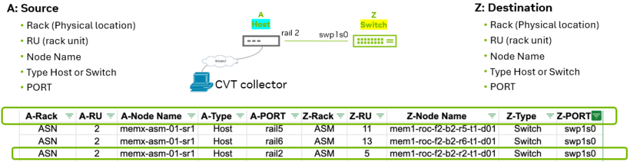
The P2P file is an Excel file that details the physical link connections within the fabric. It may consist of multiple sheets, each containing the following columns:
-
A-Node Name: Specify the name of the node on the "A" side of the connection.
-
A-Type: Indicate the role of the "A" side node, either "Host" or "Switch" (applicable for Ethernet).
-
A-Port: Provide the port name for the "A" side node.
-
Z-Node Name: Specify the name of the node on the "Z" side of the connection.
-
Z-Type: Indicate the role of the "Z" side node, either "Host" or "Switch" (applicable for Ethernet).
-
Z-Port: Provide the port name for the "Z" side node.
P2P Examples
InfiniBand Example:
A sample sheet for InfiniBand connections in a P2P file:
|
Rack |
U |
Name |
HCA/Port |
Rack |
Name |
Name |
Port |
|---|---|---|---|---|---|---|---|
|
PXH |
28 |
swx-proton03 |
1 |
PXX |
30 |
sw-hdr-proton01 |
1/3 |
|
316 |
24 |
swx-proton04 |
3 |
PXX |
27 |
sw-hdr-proton01 |
1/4 |
-
The designated port can be a single number or a split port (e.g., 1/2).
-
Mapping for HCA ports:
-
1 → mlx5_0 P1
-
2 → mlx5_1 P1
-
And so on.
-
The HCA mapping could be customized by the user, for more details see HCA Mapping File
XDR Example:
A sample sheet for NVOS connections in a P2P file:
|
Rack |
U |
Name |
HCA/Port |
Rack |
Name |
Name |
Port |
|---|---|---|---|---|---|---|---|
|
316 |
22 |
clx-abc-073 |
1 |
R113 |
22 |
bm-abc-t4 |
sw1p1 |
|
316 |
24 |
clx-abc-074 |
1 |
R113 |
22 |
bm-abc-t5 |
sw1p2 |
-
Designated ports are represented as
sw<port_number>p<split_number>for switches. -
Mapping for HCA ports: Same as InfiniBand (see above).
Ethernet Example:
|
A-Rack |
A-U |
A-Node Name |
A-Type |
A-Port |
Z-Rack |
Z-RU |
Z-Node Name |
Z-Type |
Z-Port |
|---|---|---|---|---|---|---|---|---|---|
|
ASN |
2 |
memx-asm-01-sr1 |
Host |
rail5 |
ASM |
11 |
mem1-roc-f2-b2-r5-t1-d01 |
Switch |
swp1s0 |
|
ASN |
2 |
memx-asm-01-sr1 |
Host |
rail6 |
ASM |
13 |
mem1-roc-f2-b2-r6-t1-d01 |
Switch |
swp1s1 |
Designated ports are represented as swp<port_number>s<split_number> for switches.
Please note that in all fabrics the tool relies on the header names to extract the information it needs. So user must have these names exactly as they appear above. If you make a syntax error then it will fail.
Legend Sheet
it is mandatory for the PTP file to incorporate a "Legend" sheet, which contains vital details regarding switch and host patterns. The below is an example:
Example:
|
Name |
Model |
Switch/HCA |
Speed |
Rate |
|---|---|---|---|---|
|
|
MQM9700 |
Switch |
4x 100G |
NDR |
|
|
HCA_2 |
HCA |
4x 100G |
NDR |
Last updated: