This guide provides instructions on how to use the DOCA HBN Service container on top of NVIDIA® BlueField® networking platform.
Introduction
Release Notes
For the release notes of HBN 2.2.0, please refer to "HBN Service Release Notes".
HBN Overview
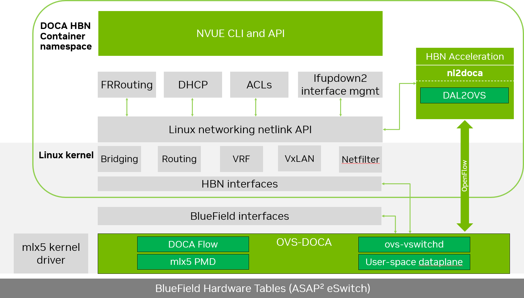
Host-based Networking (HBN) is a DOCA service that enables the network architect to design a network purely on L3 protocols, enabling routing to run on the server-side of the network by using the BlueField as a BGP router. The EVPN extension of BGP, supported by HBN, extends the L3 underlay network to multi-tenant environments with overlay L2 and L3 isolated networks.
The HBN solution packages a set of network functions inside a container which, itself, is packaged as a service pod to be run on BlueField Arm. At the core of HBN is the Linux networking BlueField acceleration driver Netlink-to-DOCA, or nl2docad. This daemon seamlessly accelerates Linux networking using DOCA APIs to program specific packet processing rules in BlueField hardware.
The driver mirrors the Linux kernel routing and bridging tables into the BlueField hardware tables by discovering the configured Linux networking objects using the Linux Netlink API. Dynamic network flows, as learned by the Linux kernel networking stack, are also programmed by the driver into BlueField hardware by listening to Linux kernel networking events.
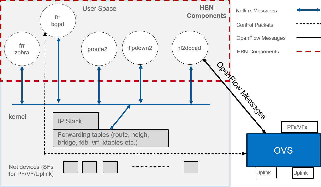
The following diagram captures an overview of HBN and the interactions between various components of HBN.
-
ifupdown2 is the interface manager which pushes all the interface related states to kernel
-
The routing stack is implemented in FRR and pushes all the control states (EVPN MACs and routes) to kernel via netlink
-
Kernel maintains the whole network state and relays the information using netlink. The kernel is also involved in the punt path and handling traffic that does not match any rules in the eSwitch.
-
nl2docad listens for the network state via netlink and invokes the DOCA interface to accelerate the flows in BlueField hardware tables. nl2docad also offloads these flows to eSwitch.
Service Function Chaining
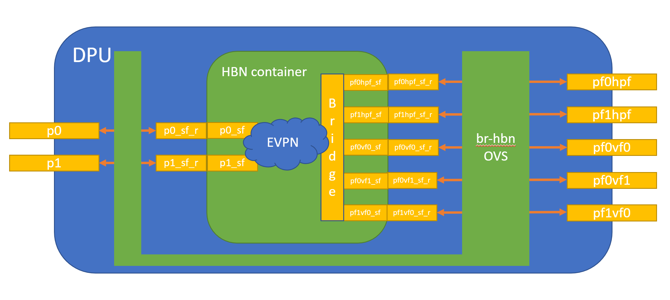
HBN is a "bump-in-the-wire" service and requires specific network configuration on BlueField called service function chaining (SFC). SFC configuration is used to redirect network traffic, which is originated from or forwarded to the host or BlueField itself via the HBN data plane.
The diagram below shows the fully detailed default configuration for HBN with SFC.
In this setup, the HBN container is configured to use sub-function ports (SFs) instead of the actual uplinks, PFs and VFs. To illustrate, for example:
-
Uplinks – use
p0_sfinstead ofp0 -
PF – use
pf0hpf_sfinstead ofpf0hpf -
VF – use
pf0vf0_sfinstead ofpf0vf0
The indirection layer between the SF and the actual ports is managed via a br-hbn OVS bridge automatically configured when the BFB image is installed on BlueField with HBN enabled. This indirection layer allows other services to be chained to existing SFs and provide additional functionality to transit traffic.
Requirements
Refer to the "HBN Service Release Notes" page for information on the specific hardware and software requirements for HBN.
The following subsections describe specific prerequisites for the BlueField before deploying the DOCA HBN Service.
Enabling BlueField DPU Mode
HBN requires BlueField to work in either DPU mode or zero-trust mode of operation. Information about configuring BlueField modes of operation can be found under "NVIDIA BlueField Modes of Operation".
Enabling SFC
HBN requires SFC configuration to be activated on the BlueField before running the HBN service container. SFC allows for additional services/containers to be chained to HBN and provides additional data manipulation capabilities.
The following subsections provide additional information about SFC and instructions on enabling it during BlueField DOCA image installation.
Deploying BlueField DOCA Image with SFC from Host
For DOCA image installation on BlueField, the user should follow the instructions under NVIDIA DOCA Installation Guide for Linux with the following extra notes to enable BlueField for HBN setup:
-
Make sure link type is set to ETH under the "Installing Software on Host" section.
-
Add the following parameters to the
bf.cfgconfiguration file:-
Enable HBN specific OVS bridge on BlueField Arm by setting ENABLE_BR_HBN=yes.
-
Define the uplink ports to be used by HBN
BR_HBN_UPLINKS='<port>'.Must include both ports (i.e.,
p0,p1) for dual-port BlueField devices and onlyp0for single-port BlueField devices. -
Include PF and VF ports to be used by HBN. The following example sets both PFs and 8 VFs on each uplink:
BR_HBN_REPS='pf0hpf,pf1hpf,pf0vf0-pf0vf7,pf1vf0-pf1vf7'. -
(Optional) Include SF devices to be created and connected to HBN bridge on the BlueField Arm side by setting
BR_HBN_SFS='pf0dpu1,pf0dpu3'.If nothing is provided,
pf0dpu1andpf0dpu3are created by default.While older formats of
bf.cfgstill work in this release, they will be deprecated over the next 2 releases. So, its advisable to move to the new format to avoid any upgrade issues in future releases. The following is an example for the oldbf.cfgformat:BashENABLE_SFC_HBN=yes NUM_VFs_PHYS_PORT0=12 # <num VFs supported by HBN on Physical Port 0> (valid range: 0-127) Default 14 NUM_VFs_PHYS_PORT1=2 # <num VFs supported by HBN on Physical Port 1> (valid range: 0-127) Default 0
-
-
Then run:
Bashbfb-install -c bf.cfg -r rshim0 -b <BFB-image>
Deploying BlueField DOCA Image with SFC Using PXE Boot
To enable HBN SFC using a PXE installation environment with BFB content, use the following configuration for PXE:
bfnet=<IFNAME>:<IPADDR>:<NETMASK> or <IFNAME>:dhcp
bfks=<URL of the kickstart script>
The kickstart script (bash) should include the following lines:
cat >> /etc/bf.cfg << EOF

ENABLE_BR_HBN=yes
BR_HBN_UPLINKS='p0,p1'
BR_HBN_REPS='pf0hpf,pf1hpf,pf0vf0-pf0vf7,pf1vf0-pf1vf7'
BR_HBN_SFS='pf0dpu1,pf0dpu3'
EOF
The /etc/bf.cfg generated above is sourced by the BFB install.sh script.
It is recommended to verify the accuracy of the BlueField's clock post-installation. This can be done using the following command:
$ date
Please refer to the known issues listed in the "NVIDIA DOCA Release Notes" for more information.
Deploying HBN with Other Services
When the HBN container is deployed by itself, BlueField Arm is configured with 3k huge pages. If it is deployed with other services, the actual number of huge-pages must be adjusted based on the requirements of those services. For example, SNAP or NVMesh need approximately 1k huge pages. So if HBN is running with either of these services on the same BlueField, the total number of huge pages must be set to 4k (3k for HBN and 1k for SNAP or NVMesh).
To do that, add the following parameters to the bf.cfg configuration file alongside other desired parameters.
HUGEPAGE_COUNT=4096
This should be performed only on a BlueField-3 running with 32G of memory. Doing this on 16G system may cause memory issues for various applications on BlueField Arm.
Service Deployment
HBN Service Container Deployment
HBN service is available on NGC, NVIDIA's container catalog. For information about the deployment of DOCA containers on top of the BlueField, refer to NVIDIA DOCA Container Deployment Guide.
Downloading DOCA Container Resource File
Pull the latest DOCA container resource as a *.zip file from NGC and extract it to the <resource> folder (doca_container_configs_2.7.0v1 in this example):
wget https://api.ngc.nvidia.com/v2/resources/nvidia/doca/doca_container_configs/versions/2.7.0v1/zip -O doca_container_configs_2.7.0v1.zip
unzip -o doca_container_configs_2.7.0v1.zip -d doca_container_configs_2.7.0v1
Running HBN Preparation Script
The HBN script (hbn-dpu-setup.sh) performs the following steps on BlueField Arm which are required for HBN service to run:
-
Sets the BlueField to DPU mode if needed.
-
Enables IPv4/IPv6 kernel forwarding.
-
Sets up interface MTU if needed.
-
Sets up mount points between BlueField Arm and HBN container for logs and configuration persistency.
-
Sets up various paths as needed by supervisord and other services inside container.
The script is located in <resource>/scripts/doca_hbn/<hbn_version>/ folder, which is downloaded as part of the DOCA Container Resource.
To achieve the desired configuration on HBN's first boot, before running preparation script, users can update default NVUE or flat (network interfaces and FRR) configuration files, which are located in <resource>/scripts/doca_hbn/<hbn_version>/.
-
For NVUE-based configuration:
-
etc/nvue.d/startup.yaml
-
-
For flat-files based configuration:
-
etc/network/interfaces -
etc/frr/frr.conf -
etc/frr/daemons
-
Run the following commands to execute the hbn-dpu-setup.sh script:
cd <resource>/scripts/doca_hbn/2.2.0/
chmod +x hbn-dpu-setup.sh
sudo ./hbn-dpu-setup.sh
After running the script, perform BlueField system-level reset.
Spawning HBN Container
HBN container .yaml configuration is called doca_hbn.yaml and it is located in <resource>/configs/<doca_version>/ directory. To spawn the HBN container, simply copy the doca_hbn.yaml file to the /etc/kubelet.d directory:
cd <resource>/configs/2.7.0/
sudo cp doca_hbn.yaml /etc/kubelet.d/
Kubelet automatically pulls the container image from NGC and spawns a pod executing the container. The DOCA HBN Service starts executing right away.
Verifying HBN Container is Running
To inspect the HBN container and verify if it is running correctly:
-
Check HBN pod and container status and logs:
-
Examine the currently active pods and their IDs (it may take up to 20 seconds for the pod to start):
Bashsudo crictl pods -
View currently active containers and their IDs:
Bashsudo crictl ps -
Examine logs of a given container:
Bashsudo crictl logs -
Examine kubelet logs if something did not work as expected:
Bashsudo journalctl -u kubelet@mgmt
-
-
Log into the HBN container:
Bashsudo crictl exec -it $(crictl ps | grep hbn | awk '{print $1;}') bash -
While logged into HBN container, verify that the
frr,nl2doca, andneighmgrservices are running:Bash(hbn-container)$ supervisorctl status frr (hbn-container)$ supervisorctl status nl2doca (hbn-container)$ supervisorctl status neighmgr -
Users may also examine various logs under
/var/loginside the HBN container.
HBN Default Deployment Configuration
The HBN service comes with four types of configurable interfaces:
-
Two uplinks (
p0_sf,p1_sf) -
Two PF port representors (
pf0hpf_sf,pf1hpf_sf) -
User-defined number of VFs (i.e.,
pf0vf0_sf,pf0vf1_sf, …,pf1vf0_sf,pf1vf1_sf, …) -
Two interfaces to connect to services running on BlueField, outside of the HBN container (
pf0dpu1_sfandpf0dpu3_sf)
The *_sf suffix indicates that these are sub-functions and are different from the physical uplinks (i.e., PFs, VFs). They can be viewed as virtual interfaces from a virtualized BlueField.
Each of these interfaces is connected outside the HBN container to the corresponding physical interface, see section "NVIDIA DOCA HBN Service Guide | id (2.7.0)NVIDIADOCAHBNServiceGuide ServiceFunctionChaining" (SFC) for more details.
The HBN container runs as an isolated namespace and does not see any interfaces outside the container (oob_net0, real uplinks and PFs, *_sf_r representors).
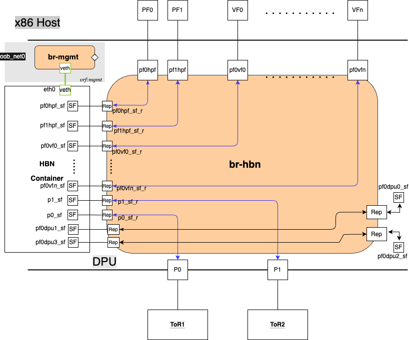
pf0dpu1_sf and pf0dpu3_sf are special interfaces for HBN to connect to services running on BlueField. Their counterparts pf0dpu0_sf and pf0dpu2_sf respectively are located outside the HBN container. See section "NVIDIA DOCA HBN Service Guide | id (2.7.0)NVIDIADOCAHBNServiceGuide ConnectingtoDOCAServicestoHBNonBlueFieldArm" for deployment considerations when using the pf0dpu1_sf or pf0dpu3_sf interface in HBN.
eth0 is equivalent to the oob_net0 interface in the HBN container. It is part of the management VRF of the container. It is not configurable via NVUE and does not need any configuration from the user. See section "NVIDIA DOCA HBN Service Guide | id (2.7.0)NVIDIADOCAHBNServiceGuide MGMTVRFInsideHBNContainer" for more details on this interface and the management VRF.
HBN Deployment Considerations
SF Interface State Tracking
When HBN is deployed with SFC, the interface state of the following network devices is propagated to their corresponding SFs:
-
Uplinks –
p0,p1 -
PFs –
pf0hpf,pf1hpf -
VFs –
pf0vfX,pf1vfXwhereXis the VF number
For example, if the p0 uplink cable gets disconnected:
-
p0transitions to DOWN state withNO-CARRIER(default behavior on Linux); and -
p0state is propagated top0_sfwhose state also becomes DOWN with NO-CARRIER
After p0 connection is reestablished:
-
p0transitions to UP state; and -
p0state is propagated top0_sfwhose state becomes UP
Interface state propagation only happens in the uplink/PF/VF-to-SF direction.
A daemon called sfc-state-propagation runs on BlueField, outside of the HBN container, to sync the state. The daemon listens to netlink notifications for interfaces and transfers the state to SFs.
SF Interface MTU
In the HBN container, all the interfaces MTU are set to 9216 by default. MTU of specific interfaces can be overwritten using flat-files configuration or NVUE.
On BlueField side (i.e., outside of the HBN container), the MTU of the uplinks, PFs and VFs interfaces are also set to 9216. This can be changed by modifying /etc/systemd/network/30-hbn-mtu.network or by adding a new configuration file in the /etc/systemd/network for specific directories.
To reload this configuration, execute systemctl restart systemd-networkd.
Connecting to DOCA Services to HBN on BlueField Arm
There are various SF ports (named pf0dpuX_sf, where X is [0..n]) on BlueField Arm, which can be used to run any services on BlueField and use HBN to provide network connectivity. These ports are always created and connected in pairs of even and odd numbered ports, where even numbered ports are on BlueField side and odd numbered port are on the HBN side. For example, pf0dpu0_sf can be used by another service running on BlueField Arm to connect to HBN port pf0dpu1_sf.
Traffic between BlueField and the outside world is hardware-accelerated when the HBN side port is an L3 interface or access-port using switch virtual interface (SVI). So, it is treated the same way as PF or VF ports from a traffic handling standpoint.
There are 2 SF port pairs created by default on BlueField Arm side so there can be 2 separate DOCA services running at same time.
Disabling BlueField Uplinks
The uplink ports must be always kept administratively up for proper operation of HBN. Otherwise, the NVIDIA® ConnectX® firmware would bring down the corresponding representor port which would cause data forwarding to stop.
Change in operational status of uplink (e.g., carrier down) would result in traffic being switched to the other uplink.
When using ECMP failover on the two uplink SFs, locally disabling one uplink does not result in traffic switching to the second uplink. Disabling local link in this case means to set one uplink admin DOWN directly on BlueField.
To test ECMP failover scenarios correctly, the uplink must be disabled from its remote counterpart (i.e., execute admin DOWN on the remote system's link which is connected to the uplink).
HBN NVUE User Credentials
The preconfigured default user credentials are as follows:
|
Username |
nvidia |
|---|---|
|
Password |
nvidia |
NVUE user credentials can be added post installation:
-
This can be done by specifying additional
–-usernameand–-passwordto the HBN startup script (refer to "NVIDIA DOCA HBN Service Guide | id (2.7.0)NVIDIADOCAHBNServiceGuide RunningHBNPreparationScript"). For example:Bashsudo ./hbn-dpu-setup.sh -u newuser -p newpassword -
After executing this script, respawn the container or start the
decrypt-user-addscript inside running HBN container:Bashsupervisorctl start decrypt-user-add decrypt-user-add: startedThe script creates a new user in the HBN container:
Bashcat /etc/passwd | grep newuser newuser:x:1001:1001::/home/newuser:/bin/bash
HBN NVUE Interface Classification
|
Interface |
Interface Type |
NVUE Type |
|---|---|---|
|
|
Uplink representor |
swp |
|
|
Uplink representor |
swp |
|
|
Loopback |
loopback |
|
|
Host representor |
swp |
|
|
Host representor |
swp |
|
|
VF representor |
swp |
|
|
VF representor |
swp |
HBN Files Persistence
The following directories are mounted from BlueField Arm to the HBN container namespace and are persistent across HBN service restarts and BlueField reboots:
|
|
BlueField Arm Mount Point |
HBN Container Mount Point |
|---|---|---|
|
Configuration file mount points |
|
|
|
|
|
|
|
|
|
|
|
|
|
|
|
|
|
|
|
Support and log file mount points |
|
|
|
|
|
SR-IOV Support in HBN
Creating SR-IOV VFs on Host
The first step to use SR-IOV is to create Virtual Functions (VFs) on the host server.
VFs can be created using the following command:
sudo echo N > /sys/class/net/<host-rep>/device/sriov_numvfs
Where:
-
<host-rep>is one of the two host representors (e.g.,ens1f0orens1f1) -
0≤
N≤16 is the desired total number of VFs-
Set
N=0 to delete all the VFs on 0≤N≤16 -
N=16 is the maximum number of VFs supported on HBN across all representors
-
Automatic Creation of VF Representors and SF Devices on BlueField
VFs created on the host must have corresponding VF representor devices and SF devices for HBN on BlueField side. For example:
-
ens1f0vf0is the first SR-IOV VF device from the first host representor; this interface is created on the host server
-
pf0vf0is the corresponding VF representor device toens1f0vf0; this device is present on the BlueField Arm side and automatically created at the same time asens1f0vf0is created by the user on the host side -
pf0vf0_sfis the corresponding SF device forpf0vf0which is used to connect the VF to HBN pipeline
The creation of the SF device for VFs is done ahead of time when provisioning the BlueField and installing the DOCA image on it, see section "NVIDIA DOCA HBN Service Guide | id (2.7.0)NVIDIADOCAHBNServiceGuide EnablingSFC" to see how to select how many SFs to create ahead of time.
The SF devices for VFs (i.e., pfXvfY) are pre-mapped to work with the corresponding VF representors when these are created with the command from the previous step.
Management VRF
Two management VRFs are automatically configured for HBN when BlueField is deployed with SFC:
-
The first management VRF is outside the HBN container on BlueField. This VRF provides separation between out-of-band (OOB) traffic (via
oob_net0ortmfifo_net0) and data-plane traffic via uplinks and PFs. -
The second management VRF is inside the HBN container and provides similar separation. The OOB traffic (via
eth0) is isolated from the traffic via the*_sfinterfaces.
MGMT VRF on BlueField Arm
The management (mgmt) VRF is enabled by default when the BlueField is deployed with SFC (see section "NVIDIA DOCA HBN Service Guide | id (2.7.0)NVIDIADOCAHBNServiceGuide EnablingSFC"). The mgmt VRF provides separation between the OOB management network and the in-band data plane network.
The uplinks and PFs/VFs use the default routing table while the oob_net0 (OOB Ethernet port) and the tmifo_net0 netdevices use the mgmt VRF to route their packets.
When logging in either via SSH or the console, the shell is by default in mgmt VRF context. This is indicated by a mgmt added to the shell prompt:
root@bf2:mgmt:/home/ubuntu#
root@bf2:mgmt:/home/ubuntu# ip vrf identify
mgmt.
When logging into the HBN container with crictl, the HBN shell will be in the default VRF. Users must switch to MGMT VRF manually if OOB access is required. Use ip vrf exec to do so.
root@bf2:mgmt:/home/ubuntu# ip vrf exec mgmt bash
The user must run ip vrf exec mgmt to perform operations requiring OOB access (e.g., apt-get update).
Network devices belonging to the mgmt VRF can be listed with the vrf utility:
root@bf2:mgmt:/home/ubuntu# vrf link list

VRF: mgmt
--------------------
tmfifo_net0      UP             00:1a:ca:ff:ff:03 <BROADCAST,MULTICAST,UP,LOWER_UP>
oob_net0         UP             08:c0:eb:c0:5a:32 <BROADCAST,MULTICAST,UP,LOWER_UP>

root@bf2:mgmt:/home/ubuntu# vrf help
vrf <OPTS>

VRF domains:
    vrf list

Links associated with VRF domains:
    vrf link list [<vrf-name>]

Tasks and VRF domain asociation:
    vrf task exec <vrf-name> <command>
    vrf task list [<vrf-name>]
    vrf task identify <pid>

    NOTE: This command affects only AF_INET and AF_INET6 sockets opened by the
          command that gets exec'ed. Specifically, it has *no* impact on netlink
          sockets (e.g., ip command).
To show the routing table for the default VRF, run:
root@bf2:mgmt:/home/ubuntu# ip route show
To show the routing table for the mgmt VRF, run:
root@bf2:mgmt:/home/ubuntu# ip route show vrf mgmt
MGMT VRF Inside HBN Container
Inside the HBN container, a separate mgmt VRF is present. Similar commands as those listed under section "NVIDIA DOCA HBN Service Guide | id (2.7.0)NVIDIADOCAHBNServiceGuide MGMTVRFonBlueFieldArm" can be used to query management routes.
The *_sf interfaces use the default routing table while the eth0 (OOB) uses the mgmt VRF to route out-of-band packets out of the container. The OOB traffic gets NATed through the oob_net0 interface on BlueField Arm, ultimately using the BlueField OOB's IP address.
When logging into the HBN container via crictl, the shell enters the default VRF context by default. Switching to the mgmt VRF can be done using the command ip vrf exec mgmt <cmd>.
Existing Services in MGMT VRF on BlueField Arm
On the BlueField Arm, outside the HBN container, a set of existing services run in the mgmt VRF context as they need OOB network access:
-
containerd
-
kubelet
-
ssh
-
docker
These services can be restarted and queried for their status using the command systemctl while adding @mgmt to the original service name. For example:
-
To restart containerd:
Bashroot@bf2:mgmt:/home/ubuntu# systemctl restart containerd@mgmt -
To query containerd status:
Bashroot@bf2:mgmt:/home/ubuntu# systemctl status containerd@mgmt
The original version of these services (without @mgmt) are not used and must not be started.
Running New Service in MGMT VRF on BlueField Arm
If a service needs OOB access to run, it can be added to the set of services running in mgmt VRF context. Adding such a service is only possible on the BlueField Arm (i.e., outside the HBN container).
To add a service to the set of mgmt VRF services:
-
Add it to
/etc/vrf/systemd.conf(if it is not present already). For example, NTP is already listed in this file. -
Run the following:
root@bf2:mgmt:/home/ubuntu# systemctl daemon-reload -
Stop and disable to the non-VRF version of the service to be able to start the mgmt VRF one:
root@bf2:mgmt:/home/ubuntu# systemctl stop ntp
root@bf2:mgmt:/home/ubuntu# systemctl disable ntp
root@bf2:mgmt:/home/ubuntu# systemctl enable ntp@mgmt
root@bf2:mgmt:/home/ubuntu# systemctl start ntp@mgmt
Configuration
To start configuring HBN, log into the HBN container:
sudo crictl exec -it $(crictl ps | grep hbn | awk '{print $1;}') bash
General Network Configuration
Flat Files Configuration
Add network interfaces and FRR configuration files to HBN to achieve the desired configuration:
-
/etc/network/interfacesRefer to NVIDIA® Cumulus® Linux documentation for more information.
-
/etc/frr/frr.conf;/etc/frr/daemonsRefer to NVIDIA® Cumulus® Linux documentation for more information.
NVUE Configuration
This section assumes familiarity with NVIDIA user experience (NVUE) Cumulus Linux documentation. The following subsections, only expand on HBN-specific aspects of NVUE.
NVUE Service
HBN installs NVUE by default and enables NVUE service at boot.
NVUE REST API
HBN enables REST API by default.
Users may run the cURL commands from the command line. Use the default HBN username nvidia and password nvidia.
To change the default password of the nvidia user or add additional users for NVUE access, refer to section "NVIDIA DOCA HBN Service Guide | id (2.7.0)NVIDIADOCAHBNServiceGuide HBNNVUEUserCredentials".
REST API example:
curl -u 'nvidia:nvidia' --insecure https://<mgmt_ip>:8765/nvue_v1/vrf/default/router/bgp
{
  "configured-neighbors": 2,
  "established-neighbors": 2,
  "router-id": "10.10.10.201"
}
For information about using the NVUE REST API, refer to the NVUE API documentation.
NVUE CLI
For information about using the NVUE CLI, refer to the NVUE CLI documentation
NVUE Startup Configuration File
When the network configuration is saved using NVUE, HBN writes the configuration to the /etc/nvue.d/startup.yaml file.
Startup configuration is applied by following the supervisor daemon at boot time. nvued-startup will appear in EXITED state after applying the startup configuration.
# supervisorctl status nvued-startup
nvued-startup                    EXITED    Apr 17 10:04 AM
nv config apply startup applies the yaml configuration saved at /etc/nvue.d/.
nv config save saves the running configuration to /etc/nvue.d/startup.yaml.
HBN Configuration Examples
HBN Default Configuration
After a fresh HBN installation, the default /etc/network/interfaces file would contain only the declaration of the two uplink SFs and a loopback interface.
source /etc/network/interfaces.d/*.intf

auto lo
iface lo inet loopback

auto p0_sf
iface p0_sf

auto p1_sf
iface p1_sf
FRR configuration files would also be present under /etc/frr/ but no configuration would be enabled.
Layer-3 Routing
Native Routing with BGP and ECMP
HBN supports unicast routing with BGP and ECMP for IPv4 and IPv6 traffic. ECMP is achieved by distributing traffic using hash calculation based on the source IP, destination IP, and protocol type of the IP header.
For TCP and UDP packets, it also includes source port and destination port.
ECMP Example
ECMP is implemented any time routes have multiple paths over uplinks or host ports. For example, 20.20.20.0/24 has 2 paths using both uplinks, so a path is selected based on a hash of the IP headers.
20.20.20.0/24 proto bgp metric 20
	nexthop via 169.254.0.1 dev p0_sf weight 1 onlink <<<<< via uplink p0_sf
	nexthop via 169.254.0.1 dev p1_sf weight 1 onlink <<<<< via uplink p1_sf
HBN supports up to 16 paths for ECMP.
Sample NVUE Configuration for Native Routing
nv set interface lo ip address 10.10.10.1/32
nv set interface lo ip address 2010:10:10::1/128
nv set interface vlan100 type svi
nv set interface vlan100 vlan 100
nv set interface vlan100 base-interface br_default
nv set interface vlan100 ip address 2030:30:30::1/64
nv set interface vlan100 ip address 30.30.30.1/24
nv set bridge domain br_default vlan 100
nv set interface pf0hpf_sf,pf1hpf_sf bridge domain br_default access 100
nv set vrf default router bgp router-id 10.10.10.1
nv set vrf default router bgp autonomous-system 65501
nv set vrf default router bgp path-selection multipath aspath-ignore on
nv set vrf default router bgp address-family ipv4-unicast enable on
nv set vrf default router bgp address-family ipv4-unicast redistribute connected enable on
nv set vrf default router bgp address-family ipv6-unicast enable on
nv set vrf default router bgp address-family ipv6-unicast redistribute connected enable on
nv set vrf default router bgp neighbor p0_sf remote-as external
nv set vrf default router bgp neighbor p0_sf type unnumbered
nv set vrf default router bgp neighbor p0_sf address-family ipv4-unicast enable on
nv set vrf default router bgp neighbor p0_sf address-family ipv6-unicast enable on
nv set vrf default router bgp neighbor p1_sf remote-as external
nv set vrf default router bgp neighbor p1_sf type unnumbered
nv set vrf default router bgp neighbor p1_sf address-family ipv4-unicast enable on
nv set vrf default router bgp neighbor p1_sf address-family ipv6-unicast enable on
Sample Flat Files Configuration for Native Routing
Example /etc/network/interfaces configuration:
auto lo
iface lo inet loopback
    address 10.10.10.1/32
    address 2010:10:10::1/128

auto p0_sf
iface p0_sf

auto p1_sf
iface p1_sf

auto pf0hpf_sf
iface pf0hpf_sf
	bridge-access 100

auto pf1hpf_sf
iface pf1hpf_sf
 	bridge-access 100

auto vlan100
iface vlan100
    address 2030:30:30::1/64
    address 30.30.30.1/24
    vlan-raw-device br_default
    vlan-id 100

auto br_default
iface br_default
    bridge-ports pf0hpf_sf pf1hpf_sf
    bridge-vlan-aware yes
    bridge-vids 100
    bridge-pvid 1
Example /etc/frr/daemons configuration:
bgpd=yes
vtysh_enable=yes


FRR Config file @ /etc/frr/frr.conf -
!
frr version 7.5+cl5.3.0u0
frr defaults datacenter
hostname BLUEFIELD2
log syslog informational
no zebra nexthop kernel enable
!
router bgp 65501
 bgp router-id 10.10.10.1
 bgp bestpath as-path multipath-relax
 neighbor p0_sf interface remote-as external
 neighbor p0_sf advertisement-interval 0
 neighbor p0_sf timers 3 9
 neighbor p0_sf timers connect 10
 neighbor p1_sf interface remote-as external
 neighbor p1_sf advertisement-interval 0
 neighbor p1_sf timers 3 9
 neighbor p1_sf timers connect 10
 !
 address-family ipv4 unicast
  redistribute connected
  maximum-paths 64
  maximum-paths ibgp 64
 exit-address-family
 !
 address-family ipv6 unicast
  redistribute connected
  neighbor p0_sf activate
  neighbor p1_sf activate
  maximum-paths 64
  maximum-paths ibgp 64
 exit-address-family
!
line vty
!
end
Direct Routing on Host-facing Interfaces
Host-facing interfaces (PFs and VFs) are not restricted to be part of the bridge for routing. HBN supports L3-only configuration with direct routing on host-facing PFs and VFs.
Sample NVUE Configuration
nv set interface pf0hpf_sf ip address 30.30.11.1/24
nv set interface pf0hpf_sf ip address 2030:30:11::1/64
nv set interface pf0vf0_sf ip address 30.30.13.1/24
nv set interface pf0vf0_sf ip address 2030:30:13::1/64
Sample Flat File Configuration
auto pf0hpf_sf
iface pf0hpf_sf
    address 2030:30:11::1/64
    address 30.30.11.1/24

auto pf0vf0_sf
iface pf0vf0_sf
    address 2030:30:13::1/64
    address 30.30.13.1/24
BGP Peering with the Host
HBN supports the ability to establish a BGP session between the host and the HBN service running on BlueField Arm and allow the host to announce arbitrary route prefixes through the BlueField into the underlay fabric. The host can use any standard BGP protocol stack implementation to establish BGP peering with HBN.
Traffic to and from endpoints on the host gets offloaded.
Both IPv4 and IPv6 unicast AFI/SAFI are supported.
It is possible to apply route filtering for these prefixes to limit the potential security impact in this configuration.
Sample NVUE Configuration for Host BGP Peering
The following code block shows configuration to peer to host at 45.3.0.4 and 2001:cafe:1ead::4. The BGP session can be established using IPv4 or IPv6 address.
Either of these sessions can support IPv4 unicast and IPv6 unicast AFI/SAFI.
NVUE configuration for peering with host:
nv set vrf default router bgp autonomous-system 63642
nv set vrf default router bgp enable on
nv set vrf default router bgp neighbor 45.3.0.4 nexthop-connected-check off
nv set vrf default router bgp neighbor 45.3.0.4 peer-group dpu_host
nv set vrf default router bgp neighbor 45.3.0.4 type numbered
nv set vrf default router bgp neighbor 2001:cafe:1ead::4 nexthop-connected-check off
nv set vrf default router bgp neighbor 2001:cafe:1ead::4 peer-group dpu_host
nv set vrf default router bgp neighbor 2001:cafe:1ead::4 type numbered
nv set vrf default router bgp peer-group dpu_host address-family ipv4-unicast enable on
nv set vrf default router bgp peer-group dpu_host address-family ipv6-unicast enable on
nv set vrf default router bgp peer-group dpu_host remote-as external
Sample Flat Files Configuration for Host BGP peering
The following block shows configuration to peer to host at 45.3.0.4 and 2001:cafe:1ead::4. The BGP session can be established using IPv4 or IPv6 address.
frr.conf file:
router bgp 63642
 bgp router-id 27.0.0.4
 bgp bestpath as-path multipath-relax
 neighbor dpu_host peer-group
 neighbor dpu_host remote-as external
 neighbor dpu_host advertisement-interval 0
 neighbor dpu_host timers 3 9
 neighbor dpu_host timers connect 10
 neighbor dpu_host disable-connected-check
 neighbor fabric peer-group
 neighbor fabric remote-as external
 neighbor fabric advertisement-interval 0
 neighbor fabric timers 3 9
 neighbor fabric timers connect 10
 neighbor 45.3.0.4 peer-group dpu_host
 neighbor 2001:cafe:1ead::4 peer-group dpu_host
 neighbor p0_sf interface peer-group fabric
 neighbor p1_sf interface peer-group fabric
 !
 address-family ipv4 unicast
	neighbor dpu_host activate
 !
 address-family ipv6 unicast
	neighbor dpu_host activate
Sample FRR configuration on the Host
Any BGP implementation can be used on the host to peer to HBN and advertise endpoints. The following is an example using FRR BGP:
Sample FRR configuration on the host:
bf2-s12# sh run
Building configuration...

Current configuration:
!
frr version 7.2.1
frr defaults traditional
hostname bf2-s12
no ip forwarding
no ipv6 forwarding
!
router bgp 1000008
!
router bgp 1000008 vrf v_200_2000
 neighbor 45.3.0.2 remote-as external
 neighbor 2001:cafe:1ead::2 remote-as external
 !
 address-family ipv4 unicast
  redistribute connected
 exit-address-family
 !
 address-family ipv6 unicast
  redistribute connected
  neighbor 45.3.0.2 activate
  neighbor 2001:cafe:1ead::2 activate
 exit-address-family
!
line vty
!
end
Sample interfaces configuration on the host:
root@bf2-s12:/home/cumulus# ifquery -a
auto lo
iface lo inet loopback
	address 27.0.0.7/32
	address 2001:c000:10ff:f00d::7/128

auto v_200_2000
iface v_200_2000
	address 60.1.0.1
	address 60.1.0.2
	address 60.1.0.3
    address 2001:60:1::1
	address 2001:60:1::2
	address 2001:60:1::3
    vrf-table auto
auto ens1f0np0
iface ens1f0np0
	address 45.3.0.4/24
	address 2001:cafe:1ead::4/64
	gateway 45.3.0.1
	gateway 2001:cafe:1ead::1
	vrf v_200_2000
	hwaddress 00:03:00:08:00:12
	mtu 9162
VRF Route Leaking
VRFs are typically used when multiple independent routing and forwarding tables are desirable. However, users may want to reach destinations in one VRF from another VRF, as in the following cases:
-
To make a service, such as a firewall available to multiple VRFs
-
To enable routing to external networks or the Internet for multiple VRFs, where the external network itself is reachable through a specific VRF
Route leaking can be used to reach remote destinations as well as directly connected destinations in another VRF. Multiple VRFs can import routes from a single source VRF, and a VRF can import routes from multiple source VRFs. This can be used when a single VRF provides connectivity to external networks or a shared service for other VRFs. It is possible to control the routes leaked dynamically across VRFs with a route map.
When route leaking is used:
-
The
redistributecommand (notnetworkcommand) must be used in BGP to leak non-BGP routes (connected or static routes) -
It is not possible to leak routes between the default and non-default VRF
Ping or other IP traffic from a locally connected host in vrfX to a local interface IP address on the BlueField/HBN in vrfY does not work, even if VRF route-leaking is enabled between these two VRFs.
In the following example commands, routes in the BGP routing table of VRF BLUE dynamically leak into VRF RED:
nv set vrf RED router bgp address-family ipv4-unicast route-import from-vrf list BLUE
nv config apply
The following example commands delete leaked routes from VRF BLUE to VRF RED:
nv unset vrf RED router bgp address-family ipv4-unicast route-import from-vrf list BLUE
nv config apply
To exclude certain prefixes from the import process, configure the prefixes in a route map.
The following example configures a route map to match the source protocol BGP and imports the routes from VRF BLUE to VRF RED. For the imported routes, the community is 11:11 in VRF RED.
nv set vrf RED router bgp address-family ipv4-unicast route-import from-vrf list BLUE
nv set router policy route-map BLUEtoRED rule 10 match type ipv4
nv set router policy route-map BLUEtoRED rule 10 match source-protocol bgp
nv set router policy route-map BLUEtoRED rule 10 action permit
nv set router policy route-map BLUEtoRED rule 10 set community 11:11
nv set vrf RED router bgp address-family ipv4-unicast route-import from-vrf route-map BLUEtoRED
nv config
To check the status of the VRF route leaking, run:
-
NVUE command:
nv show vrf <vrf-name> router bgp address-family ipv4-unicast route-import -
Vtysh command:
show ip bgp vrf <vrf-name> ipv4|ipv6 unicast route-leak command. -
For example:
nv show vrf RED router bgp address-family ipv4-unicast route-import
                operational   applied
--------------  ------------  ---------
from-vrf
  enable                      on
  route-map                   BLUEtoRED
  [list]        BLUE          BLUE
[route-target]  10.10.10.1:3
To show more detailed status information, the following NVUE commands are available:
-
nv show vrf <vrf-name> router bgp address-family ipv4-unicast route-import from-vrf -
nv show vrf <vrf-name> router bgp address-family ipv4-unicast route-import from-vrf list -
nv show vrf <vrf-name> router bgp address-family ipv4-unicast route-import from-vrf list <leak-vrf-id>
To view the BGP routing table, run:
-
NVUE command:
nv show vrf <vrf-name> router bgp address-family ipv4-unicast -
Vtysh command:
show ip bgp vrf <vrf-name> ipv4|ipv6 unicast
To view the FRR IP routing table, run:
-
Vtysh command:
show ip route vrf <vrf-name> -
Or:
net show route vrf <vrf-name>These commands show all routes, including routes leaked from other VRFs.
VLAN Subinterfaces
A VLAN subinterface is a VLAN device on an interface. The VLAN ID appends to the parent interface using dot (.) VLAN notation which is a standard way to specify a VLAN device in Linux.
For example:
-
A VLAN with ID 100 which is a subinterface of
p0_sfis annotated asp0_sf.100 -
The subinterface
p0_sf.100only receives packets that have a VLAN 100 tag on portp0_sf -
Any packets transmitted from
p0_sf.100would have VLAN tag 100
In HBN, VLAN subinterfaces can be created on uplink ports as well as on the host-facing PF and VF ports. A VLAN subinterface only receives traffic tagged for that VLAN.
VLAN subinterfaces are L3 interfaces and should not be added to a bridge.
In the following example, uplink subinterface on p0_sf with VLAN ID 10 and a host facing subinterface on VF ports pf1vf0_sf with VLAN ID 999 are created. The host-facing subinterface is also assigned with IPv4 and IPv6 addresses.
Subinterface configuration using NVUE commands:
nv set interface p0_sf.10 base-interface p0_sf
nv set interface p0_sf.10 type sub
nv set interface p0_sf.10 vlan 10

nv set interface pf1vf0_sf type swp
nv set interface pf1vf0_sf.999 base-interface pf1vf0_sf
nv set interface pf1vf0_sf.999 type sub
nv set interface pf1vf0_sf.999 vlan 999
nv set interface pf1vf0_sf ip address 30.30.14.1/24
nv set interface pf1vf0_sf ip address 2030:30:14::1/64
Same configuration using sample flat file in /etc/network/interfaces:
auto p0_sf.10
iface p0_sf.10

auto pf1vf0_sf.999
iface pf1vf0_sf.999
    address 2030:30:40::1/64
    address 30.30.40.1/24
Ethernet Virtual Private Network – EVPN
HBN supports VXLAN with EVPN control plane for intra-subnet bridging (L2) services for IPv4 and IPv6 traffic in the overlay.
For the underlay, only IPv4 or BGP unnumbered configuration is supported.
HBN supports VXLAN encapsulation only over uplink parent interfaces.
Single VXLAN Device
With a single VXLAN device, a set of VXLAN network identifiers (VNIs) represents a single device model. The single VXLAN device has a set of attributes that belong to the VXLAN construct. Individual VNIs include VLAN-to-VNI mapping which allows users to specify which VLANs are associated with which VNIs. A single VXLAN device simplifies the configuration and reduces the overhead by replacing multiple traditional VXLAN devices with a single VXLAN device.
Users may configure a single VXLAN device automatically with NVUE, or manually by editing the /etc/network/interfaces file. When users configure a single VXLAN device with NVUE, NVUE creates a unique name for the device in the following format using the bridge name as the hash key: vxlan<id>.
This example configuration performs the following steps:
-
Creates a single VXLAN device (vxlan21).
-
Maps VLAN 10 to VNI 10 and VLAN 20 to VNI 20.
-
Adds the VXLAN device to the default bridge.
cumulus@leaf01:~$ nv set bridge domain bridge vlan 10 vni 10
cumulus@leaf01:~$ nv set bridge domain bridge vlan 20 vni 20
cumulus@leaf01:~$ nv set nve vxlan source address 10.10.10.1
cumulus@leaf01:~$ nv config apply
Alternately, users may edit the file /etc/network/interfaces as follows, then run the ifreload -a command to apply the SVD configuration.
auto lo
iface lo inet loopback
    vxlan-local-tunnelip 10.10.10.1

auto vxlan21
iface vxlan21
    bridge-vlan-vni-map 10=10 20=20
    bridge-learning off

auto bridge
iface bridge
    bridge-vlan-aware yes
    bridge-ports vxlan21 pf0hpf_sf pf1hpf_sf
    bridge-vids 10 20
    bridge-pvid 1
Users may not use a combination of single and traditional VXLAN devices.
Sample Switch Configuration for EVPN
The following is a sample NVUE config for underlay switches (NVIDIA® Spectrum® with Cumulus Linux) to enable EVPN deployments with HBN.
It assumes that the uplinks on all BlueField devices are connected to ports swp1-4 on the switch.
nv set evpn enable on
nv set router bgp enable on

nv set vrf default router bgp address-family ipv4-unicast enable on
nv set vrf default router bgp address-family ipv4-unicast redistribute connected enable on

nv set vrf default router bgp address-family l2vpn-evpn enable on
nv set vrf default router bgp autonomous-system 63640
nv set vrf default router bgp enable on
nv set vrf default router bgp neighbor swp1 peer-group fabric
nv set vrf default router bgp neighbor swp1 type unnumbered
nv set vrf default router bgp neighbor swp2 peer-group fabric
nv set vrf default router bgp neighbor swp2 type unnumbered
nv set vrf default router bgp neighbor swp3 peer-group fabric
nv set vrf default router bgp neighbor swp3 type unnumbered
nv set vrf default router bgp neighbor swp4 peer-group fabric
nv set vrf default router bgp neighbor swp4 type unnumbered
nv set vrf default router bgp path-selection multipath aspath-ignore on
nv set vrf default router bgp peer-group fabric address-family ipv4-unicast enable on
nv set vrf default router bgp peer-group fabric address-family ipv6-unicast enable on
nv set vrf default router bgp peer-group fabric address-family l2vpn-evpn add-path-tx off
nv set vrf default router bgp peer-group fabric address-family l2vpn-evpn enable on
nv set vrf default router bgp peer-group fabric remote-as external
nv set vrf default router bgp router-id 27.0.0.10

nv set interface lo ip address 2001:c000:10ff:f00d::10/128
nv set interface lo ip address 27.0.0.10/32
nv set interface lo type loopback
nv set interface swp1,swp2,swp3,swp4 type swp
Layer-2 EVPN
Sample NVUE Configuration for L2 EVPN
The following is a sample NVUE configuration which has L2-VNIs (2000, 2001) for EVPN bridging on BlueField.
nv set bridge domain br_default encap 802.1Q
nv set bridge domain br_default type vlan-aware
nv set bridge domain br_default vlan 200 vni 2000 flooding enable auto
nv set bridge domain br_default vlan 200 vni 2000 mac-learning off
nv set bridge domain br_default vlan 201 vni 2001 flooding enable auto
nv set bridge domain br_default vlan 201 vni 2001 mac-learning off

nv set evpn enable on
nv set nve vxlan arp-nd-suppress on
nv set nve vxlan enable on
nv set nve vxlan mac-learning off
nv set nve vxlan source address 27.0.0.4
nv set router bgp enable on
nv set system global anycast-mac 44:38:39:42:42:07
nv set vrf default router bgp address-family ipv4-unicast enable on
nv set vrf default router bgp address-family ipv4-unicast redistribute connected enable on

nv set vrf default router bgp address-family l2vpn-evpn enable on
nv set vrf default router bgp autonomous-system 63642
nv set vrf default router bgp enable on
nv set vrf default router bgp neighbor p0_sf peer-group fabric
nv set vrf default router bgp neighbor p0_sf type unnumbered
nv set vrf default router bgp neighbor p1_sf peer-group fabric
nv set vrf default router bgp neighbor p1_sf type unnumbered
nv set vrf default router bgp path-selection multipath aspath-ignore on
nv set vrf default router bgp peer-group fabric address-family ipv4-unicast enable on
nv set vrf default router bgp peer-group fabric address-family ipv4-unicast policy outbound route-map MY_ORIGIN_ASPATH_ONLY
nv set vrf default router bgp peer-group fabric address-family ipv6-unicast enable on
nv set vrf default router bgp peer-group fabric address-family ipv6-unicast policy outbound route-map MY_ORIGIN_ASPATH_ONLY
nv set vrf default router bgp peer-group fabric address-family l2vpn-evpn add-path-tx off
nv set vrf default router bgp peer-group fabric address-family l2vpn-evpn enable on
nv set vrf default router bgp peer-group fabric remote-as external
nv set vrf default router bgp router-id 27.0.0.4

nv set interface lo ip address 2001:c000:10ff:f00d::4/128
nv set interface lo ip address 27.0.0.4/32
nv set interface lo type loopback
nv set interface p0_sf,p1_sf,pf0hpf_sf,pf1hpf_sf type swp
nv set interface pf0hpf_sf bridge domain br_default access 200
nv set interface pf1hpf_sf bridge domain br_default access 201

nv set interface vlan200-201 base-interface br_default
nv set interface vlan200-201 ip ipv4 forward on
nv set interface vlan200-201 ip ipv6 forward on
nv set interface vlan200-201 ip vrr enable on
nv set interface vlan200-201 ip vrr state up
nv set interface vlan200-201 link mtu 9050
nv set interface vlan200-201 type svi
nv set interface vlan200 ip address 2001:cafe:1ead::3/64
nv set interface vlan200 ip address 45.3.0.2/24
nv set interface vlan200 ip vrr address 2001:cafe:1ead::1/64
nv set interface vlan200 ip vrr address 45.3.0.1/24
nv set interface vlan200 vlan 200
nv set interface vlan201 ip address 2001:cafe:1ead:1::3/64
nv set interface vlan201 ip address 45.3.1.2/24
nv set interface vlan201 ip vrr address 2001:cafe:1ead:1::1/64
nv set interface vlan201 ip vrr address 45.3.1.1/24
nv set interface vlan201 vlan 201
Sample Flat Files Configuration for L2 EVPN
The following is a sample flat files configuration which has L2-VNIs (vx-2000, vx-2001) for EVPN bridging on BlueField.
This file is located at /etc/network/interfaces:
auto lo
iface lo inet loopback
    address 2001:c000:10ff:f00d::4/128
    address 27.0.0.4/32
    vxlan-local-tunnelip 27.0.0.4

auto p0_sf
iface p0_sf

auto p1_sf
iface p1_sf

auto pf0hpf_sf
iface pf0hpf_sf
    bridge-access 200

auto pf1hpf_sf
iface pf1hpf_sf
    bridge-access 201

auto vlan200
iface vlan200
    address 2001:cafe:1ead::3/64
    address 45.3.0.2/24
    mtu 9050
    address-virtual 00:00:5e:00:01:01 2001:cafe:1ead::1/64 45.3.0.1/24
    vlan-raw-device br_default
    vlan-id 200

auto vlan201
iface vlan201
    address 2001:cafe:1ead:1::3/64
    address 45.3.1.2/24
    mtu 9050
    address-virtual 00:00:5e:00:01:01 2001:cafe:1ead:1::1/64 45.3.1.1/24
    vlan-raw-device br_default
    vlan-id 201

auto vxlan48
iface vxlan48
    bridge-vlan-vni-map 200=2000 201=2001
217=2017
    bridge-learning off

auto br_default
iface br_default
    bridge-ports pf0hpf_sf pf1hpf_sf vxlan48
    bridge-vlan-aware yes
    bridge-vids 200 201
    bridge-pvid 1
This file tells the frr package which daemon to start and is located at /etc/frr/daemons:
bgpd=yes
ospfd=no
ospf6d=no
isisd=no
pimd=no
ldpd=no
pbrd=no
vrrpd=no
fabricd=no
nhrpd=no
eigrpd=no
babeld=no
sharpd=no
fabricd=no
ripngd=no
ripd=no

vtysh_enable=yes
zebra_options="  -M cumulus_mlag -M snmp -A 127.0.0.1 -s 90000000"
bgpd_options="   -M snmp -A 127.0.0.1"
ospfd_options="  -M snmp -A 127.0.0.1"
ospf6d_options=" -M snmp -A ::1"
ripd_options="   -A 127.0.0.1"
ripngd_options=" -A ::1"
isisd_options="  -A 127.0.0.1"
pimd_options="   -A 127.0.0.1"
ldpd_options="   -A 127.0.0.1"
nhrpd_options="  -A 127.0.0.1"
eigrpd_options=" -A 127.0.0.1"
babeld_options=" -A 127.0.0.1"
sharpd_options=" -A 127.0.0.1"
pbrd_options="   -A 127.0.0.1"
staticd_options="-A 127.0.0.1"
fabricd_options="-A 127.0.0.1"
vrrpd_options="  -A 127.0.0.1"

frr_profile="datacenter"
FRR configuration file is located at /etc/frr/frr.conf:
!---- Cumulus Defaults ----
frr defaults datacenter
log syslog informational
no zebra nexthop kernel enable
vrf default
outer bgp 63642 vrf default
bgp router-id 27.0.0.4
bgp bestpath as-path multipath-relax
timers bgp 3 9
bgp deterministic-med
! Neighbors
neighbor fabric peer-group
neighbor fabric remote-as external
neighbor fabric timers 3 9
neighbor fabric timers connect 10
neighbor fabric advertisement-interval 0
neighbor p0_sf interface peer-group fabric
neighbor p1_sf interface peer-group fabric
address-family ipv4 unicast
maximum-paths ibgp 64
maximum-paths 64
distance bgp 20 200 200
neighbor fabric activate
exit-address-family
address-family ipv6 unicast
maximum-paths ibgp 64
maximum-paths 64
distance bgp 20 200 200
neighbor fabric activate
exit-address-family
address-family l2vpn evpn
advertise-all-vni
neighbor fabric activate
exit-address-family
Layer-3 EVPN with Symmetric Routing
In distributed symmetric routing, each VXLAN endpoint (VTEP) acts as a layer-3 gateway, performing routing for its attached hosts. However, both the ingress VTEP and egress VTEP route the packets (similar to traditional routing behavior of routing to a next-hop router). In a VXLAN encapsulated packet, the inner destination MAC address is the router MAC address of the egress VTEP to indicate that the egress VTEP is the next hop and that it must also perform the routing.
All routing happens in the context of a tenant (VRF). For a packet that the ingress VTEP receives from a locally attached host, the SVI interface corresponding to the VLAN determines the VRF. For a packet that the egress VTEP receives over the VXLAN tunnel, the VNI in the packet has to specify the VRF. For symmetric routing, this is a VNI corresponding to the tenant and is different from either the source VNI or the destination VNI. This VNI is a layer-3 VNI or interconnecting VNI. The regular VNI, which maps a VLAN, is the layer-2 VNI.
For more details about this, refer to the Cumulus Linux User Manual.
HBN uses a one-to-one mapping between an L3 VNI and a tenant (VRF).
The VRF to L3 VNI mapping has to be consistent across all VTEPs.
An L3 VNI and an L2 VNI cannot have the same ID.
In an EVPN symmetric routing configuration, when the switch announces a type-2 (MAC/IP) route, in addition to containing two VNIs (L2 and L3 VNIs), the route also contains separate route targets (RTs) for L2 and L3. The L3 RT associates the route with the tenant VRF. By default, this is auto-derived using the L3 VNI instead of the L2 VNI. However, this is configurable.
For EVPN symmetric routing, users must perform the configuration listed in the following subsections. Optional configuration includes configuring a route distinguisher (RD) and RTs for the tenant VRF, and advertising the locally-attached subnets.
Sample NVUE Configuration for L3 EVPN
If using NVUE to configure EVPN symmetric routing, the following is a sample configuration using NVUE commands:
nv set bridge domain br_default vlan 111 vni 1000111
nv set bridge domain br_default vlan 112 vni 1000112
nv set bridge domain br_default vlan 213 vni 1000213
nv set bridge domain br_default vlan 214 vni 1000214
nv set evpn enable on
nv set interface lo ip address 6.0.0.19/32
nv set interface lo type loopback
nv set interface p0_sf description 'alias p0_sf to leaf-21 swp3'
nv set interface p0_sf,p1_sf,pf0hpf_sf,pf0vf0_sf,pf1hpf_sf,pf1vf0_sf type swp
nv set interface p1_sf description 'alias p1_sf to leaf-22 swp3'
nv set interface pf0hpf_sf bridge domain br_default access 111
nv set interface pf0hpf_sf description 'alias pf0hpf_sf to host-211 ens2f0np0'
nv set interface pf0vf0_sf bridge domain br_default access 112
nv set interface pf0vf0_sf description 'alias pf0vf0_sf to host-211 ens2f0np0v0'
nv set interface pf1hpf_sf bridge domain br_default access 213
nv set interface pf1hpf_sf description 'alias pf1hpf_sf to host-211 ens2f1np1'
nv set interface pf1vf0_sf bridge domain br_default access 214
nv set interface pf1vf0_sf description 'alias pf1vf0_sf to host-211 ens2f1np0v0'
nv set interface vlan111 ip address 60.1.1.21/24
nv set interface vlan111 ip address 2060:1:1:1::21/64
nv set interface vlan111 ip vrr address 60.1.1.250/24
nv set interface vlan111 ip vrr address 2060:1:1:1::250/64
nv set interface vlan111 vlan 111
nv set interface vlan111,213 ip vrf vrf2
nv set interface vlan111-112,213-214 ip vrr enable on
nv set interface vlan111-112,213-214 ip vrr mac-address 00:00:5e:00:01:01
nv set interface vlan111-112,213-214 ip ipv4 forward on
nv set interface vlan111-112,213-214 ip ipv6 forward on
nv set interface vlan111-112,213-214 type svi
nv set interface vlan112 ip address 50.1.1.21/24
nv set interface vlan112 ip address 2050:1:1:1::21/64
nv set interface vlan112 ip vrr address 50.1.1.250/24
nv set interface vlan112 ip vrr address 2050:1:1:1::250/64
nv set interface vlan112 vlan 112
nv set interface vlan112,214 ip vrf vrf1
nv set interface vlan213 ip address 60.1.210.21/24
nv set interface vlan213 ip address 2060:1:1:210::21/64
nv set interface vlan213 ip vrr address 60.1.210.250/24
nv set interface vlan213 ip vrr address 2060:1:1:210::250/64
nv set interface vlan213 vlan 213
nv set interface vlan214 ip address 50.1.210.21/24
nv set interface vlan214 ip address 2050:1:1:210::21/64
nv set interface vlan214 ip vrr address 50.1.210.250/24
nv set interface vlan214 ip vrr address 2050:1:1:210::250/64
nv set interface vlan214 vlan 214
nv set nve vxlan arp-nd-suppress on
nv set nve vxlan enable on
nv set nve vxlan source address 6.0.0.19
nv set platform
nv set router bgp enable on
nv set router policy route-map ALLOW_LOBR rule 10 action permit
nv set router policy route-map ALLOW_LOBR rule 10 match interface lo
nv set router policy route-map ALLOW_LOBR rule 20 action permit
nv set router policy route-map ALLOW_LOBR rule 20 match interface br_default
nv set router policy route-map ALLOW_VRF1 rule 10 action permit
nv set router policy route-map ALLOW_VRF1 rule 10 match interface vrf1
nv set router policy route-map ALLOW_VRF2 rule 10 action permit
nv set router policy route-map ALLOW_VRF2 rule 10 match interface vrf2
nv set router vrr enable on
nv set system global system-mac 00:01:00:00:1e:03
nv set vrf default router bgp address-family ipv4-unicast enable on
nv set vrf default router bgp address-family ipv4-unicast multipaths ebgp 16
nv set vrf default router bgp address-family ipv4-unicast redistribute connected enable on
nv set vrf default router bgp address-family ipv4-unicast redistribute connected route-map ALLOW_LOBR
nv set vrf default router bgp address-family l2vpn-evpn enable on
nv set vrf default router bgp autonomous-system 650019
nv set vrf default router bgp enable on
nv set vrf default router bgp neighbor p0_sf address-family l2vpn-evpn add-path-tx off
nv set vrf default router bgp neighbor p0_sf address-family l2vpn-evpn enable on
nv set vrf default router bgp neighbor p0_sf peer-group TOR_LEAF_SPINE
nv set vrf default router bgp neighbor p0_sf remote-as external
nv set vrf default router bgp neighbor p0_sf type unnumbered
nv set vrf default router bgp neighbor p1_sf address-family l2vpn-evpn add-path-tx off
nv set vrf default router bgp neighbor p1_sf address-family l2vpn-evpn enable on
nv set vrf default router bgp neighbor p1_sf peer-group TOR_LEAF_SPINE
nv set vrf default router bgp neighbor p1_sf remote-as external
nv set vrf default router bgp neighbor p1_sf type unnumbered
nv set vrf default router bgp path-selection multipath aspath-ignore on
nv set vrf default router bgp path-selection routerid-compare on
nv set vrf default router bgp peer-group TOR_LEAF_SPINE address-family ipv4-unicast enable on
nv set vrf default router bgp router-id 6.0.0.19
nv set vrf vrf1 evpn enable on
nv set vrf vrf1 evpn vni 104001
nv set vrf vrf1 loopback ip address 50.1.21.21/32
nv set vrf vrf1 loopback ip address 2050:50:50:21::21/128
nv set vrf vrf1 router bgp address-family ipv4-unicast enable on
nv set vrf vrf1 router bgp address-family ipv4-unicast redistribute connected enable on
nv set vrf vrf1 router bgp address-family ipv4-unicast redistribute connected route-map ALLOW_VRF1
nv set vrf vrf1 router bgp address-family ipv4-unicast route-export to-evpn enable on
nv set vrf vrf1 router bgp address-family ipv6-unicast enable on
nv set vrf vrf1 router bgp address-family ipv6-unicast redistribute connected enable on
nv set vrf vrf1 router bgp address-family ipv6-unicast redistribute connected route-map ALLOW_VRF1
nv set vrf vrf1 router bgp address-family ipv6-unicast route-export to-evpn enable on
nv set vrf vrf1 router bgp autonomous-system 650019
nv set vrf vrf1 router bgp enable on
nv set vrf vrf1 router bgp router-id 50.1.21.21
nv set vrf vrf2 evpn enable on
nv set vrf vrf2 evpn vni 104002
nv set vrf vrf2 loopback ip address 60.1.21.21/32
nv set vrf vrf2 loopback ip address 2060:60:60:21::21/128
nv set vrf vrf2 router bgp address-family ipv4-unicast enable on
nv set vrf vrf2 router bgp address-family ipv4-unicast redistribute connected enable on
nv set vrf vrf2 router bgp address-family ipv4-unicast redistribute connected route-map ALLOW_VRF2
nv set vrf vrf2 router bgp address-family ipv4-unicast route-export to-evpn enable on
nv set vrf vrf2 router bgp address-family ipv6-unicast enable on
nv set vrf vrf2 router bgp address-family ipv6-unicast redistribute connected enable on
nv set vrf vrf2 router bgp address-family ipv6-unicast redistribute connected route-map ALLOW_VRF2
nv set vrf vrf2 router bgp address-family ipv6-unicast route-export to-evpn enable on
nv set vrf vrf2 router bgp autonomous-system 650019
nv set vrf vrf2 router bgp enable on
nv set vrf vrf2 router bgp router-id 60.1.21.21
Sample Flat Files Configuration for L3 EVPN
The following is a sample flat files configuration which has L2 VNIs and L3 VNIs for EVPN bridging and symmetric routing on BlueField.
This file is located at /etc/network/interfaces:
auto lo
iface lo inet loopback
    address 6.0.0.19/32
    vxlan-local-tunnelip 6.0.0.19

auto vrf1
iface vrf1
    address 2050:50:50:21::21/128
    address 50.1.21.21/32
    vrf-table auto

auto vrf2
iface vrf2
    address 2060:60:60:21::21/128
    address 60.1.21.21/32
    vrf-table auto

auto p0_sf
iface p0_sf
    alias alias p0_sf to leaf-21 swp3

auto p1_sf
iface p1_sf
    alias alias p1_sf to leaf-22 swp3

auto pf0hpf_sf
iface pf0hpf_sf
    alias alias pf0hpf_sf to host-211 ens2f0np0
    bridge-access 111

auto pf0vf0_sf
iface pf0vf0_sf
    alias alias pf0vf0_sf to host-211 ens2f0np0v0
    bridge-access 112

auto pf1hpf_sf
iface pf1hpf_sf
    alias alias pf1hpf_sf to host-211 ens2f1np1
    bridge-access 213

auto pf1vf0_sf
iface pf1vf0_sf
    alias alias pf1vf0_sf to host-211 ens2f1np0v0
    bridge-access 214

auto vlan111
iface vlan111
    address 2060:1:1:1::21/64
    address 60.1.1.21/24
    address-virtual 00:00:5e:00:01:01 2060:1:1:1::250/64 60.1.1.250/24
    hwaddress 00:01:00:00:1e:03
    vrf vrf2
    vlan-raw-device br_default
    vlan-id 111

auto vlan112
iface vlan112
    address 2050:1:1:1::21/64
    address 50.1.1.21/24
    address-virtual 00:00:5e:00:01:01 2050:1:1:1::250/64 50.1.1.250/24
    hwaddress 00:01:00:00:1e:03
    vrf vrf1
    vlan-raw-device br_default
    vlan-id 112

auto vlan213
iface vlan213
    address 2060:1:1:210::21/64
    address 60.1.210.21/24
    address-virtual 00:00:5e:00:01:01 2060:1:1:210::250/64 60.1.210.250/24
    hwaddress 00:01:00:00:1e:03
    vrf vrf2
    vlan-raw-device br_default
    vlan-id 213

auto vlan214
iface vlan214
    address 2050:1:1:210::21/64
    address 50.1.210.21/24
    address-virtual 00:00:5e:00:01:01 2050:1:1:210::250/64 50.1.210.250/24
    hwaddress 00:01:00:00:1e:03
    vrf vrf1
    vlan-raw-device br_default
    vlan-id 214

auto vlan4058_l3
iface vlan4058_l3
    vrf vrf1
    vlan-raw-device br_default
    address-virtual none
    vlan-id 4058

auto vlan4059_l3
iface vlan4059_l3
    vrf vrf2
    vlan-raw-device br_default
    address-virtual none
    vlan-id 4059

auto vxlan48
iface vxlan48
    bridge-vlan-vni-map 111=1000111 112=1000112 213=1000213 214=1000214 4058=104001 4059=104002
    bridge-learning off

auto br_default
iface br_default
    bridge-ports pf0hpf_sf pf0vf0_sf pf1hpf_sf pf1vf0_sf vxlan48
    hwaddress 00:01:00:00:1e:03
    bridge-vlan-aware yes
    bridge-vids 111 112 213 214
    bridge-pvid 1
FRR configuration is located at /etc/frr/frr.conf:
frr version 8.4.3
frr defaults datacenter
hostname doca-hbn-service-bf3-s05-1-ipmi
log syslog informational
no zebra nexthop kernel enable
service integrated-vtysh-config
!
vrf vrf1
 vni 104001
exit-vrf
!
vrf vrf2
 vni 104002
exit-vrf
!
router bgp 650019
 bgp router-id 6.0.0.19
 bgp bestpath as-path multipath-relax
 bgp bestpath compare-routerid
 neighbor TOR_LEAF_SPINE peer-group
 neighbor TOR_LEAF_SPINE advertisement-interval 0
 neighbor TOR_LEAF_SPINE timers 3 9
 neighbor TOR_LEAF_SPINE timers connect 10
 neighbor p0_sf interface peer-group TOR_LEAF_SPINE
 neighbor p0_sf remote-as external
 neighbor p0_sf advertisement-interval 0
 neighbor p0_sf timers 3 9
 neighbor p0_sf timers connect 10
 neighbor p1_sf interface peer-group TOR_LEAF_SPINE
 neighbor p1_sf remote-as external
 neighbor p1_sf advertisement-interval 0
 neighbor p1_sf timers 3 9
 neighbor p1_sf timers connect 10
 !
 address-family ipv4 unicast
  redistribute connected route-map ALLOW_LOBR
  maximum-paths 16
  maximum-paths ibgp 64
 exit-address-family
 !
 address-family l2vpn evpn
  neighbor p0_sf activate
  neighbor p1_sf activate
  advertise-all-vni
 exit-address-family
exit
!
router bgp 650019 vrf vrf1
 bgp router-id 50.1.21.21
 !
 address-family ipv4 unicast
  redistribute connected route-map ALLOW_VRF1
  maximum-paths 64
  maximum-paths ibgp 64
 exit-address-family
 !
 address-family ipv6 unicast
  redistribute connected route-map ALLOW_VRF1
  maximum-paths 64
  maximum-paths ibgp 64
 exit-address-family
 !
 address-family l2vpn evpn
  advertise ipv4 unicast
  advertise ipv6 unicast
 exit-address-family
exit
!
router bgp 650019 vrf vrf2
 bgp router-id 60.1.21.21
 !
 address-family ipv4 unicast
  redistribute connected route-map ALLOW_VRF2
  maximum-paths 64
  maximum-paths ibgp 64
 exit-address-family
 !
 address-family ipv6 unicast
  redistribute connected route-map ALLOW_VRF2
  maximum-paths 64
  maximum-paths ibgp 64
 exit-address-family
 !
 address-family l2vpn evpn
  advertise ipv4 unicast
  advertise ipv6 unicast
 exit-address-family
exit
!
route-map ALLOW_LOBR permit 10
 match interface lo
exit
!
route-map ALLOW_LOBR permit 20
 match interface br_default
exit
!
route-map ALLOW_VRF1 permit 10
 match interface vrf1
exit
!
route-map ALLOW_VRF2 permit 10
 match interface vrf2
exit
Multi-hop eBGP Peering for EVPN (Route Server in Symmetric EVPN Routing)
eBGP multi-hop peering for EVPN support in a route server-like role in EVPN topology, allows the deployment of EVPN on any cloud that supports IP transport.
Route servers and BF/HBN VTEPs are connected via the IP cloud. That is:
-
Switches in the cloud provider need not be EVPN-aware
-
Switches in the provider fabric provide IPv4 and IPv6 transport and do not have to support EVPN
Sample Route Server Configuration for EVPN
The following is a sample configuration of an Ubuntu server running FRR 9.0 stable, configured as EVPN route server and an HBN VTEP that is peering to two spine switches for IP connectivity and 3 Route servers for EVPN overlay control.
root@sn1:/home/cumulus# uname -a
Linux sn1 5.15.0-88-generic #98-Ubuntu SMP Mon Oct 2 15:18:56 UTC 2023 x86_64 x86_64 x86_64 GNU/Linux
root@sn1:/home/cumulus# dpkg -l frr
Desired=Unknown/Install/Remove/Purge/Hold
| Status=Not/Inst/Conf-files/Unpacked/halF-conf/Half-inst/trig-aWait/Trig-pend
|/ Err?=(none)/Reinst-required (Status,Err: uppercase=bad)
||/ Name           Version               Architecture Description
+++-==============-=====================-============-=============================================================
ii  frr            9.0.1-0~ubuntu22.04.1 amd64        FRRouting suite of internet protocols (BGP, OSPF, IS-IS, ...)
root@sn1:/home/cumulus#
FRR configuration (frr.conf):
sn1# sh run
Building configuration...

Current configuration:
!
frr version 9.0.1
frr defaults datacenter
hostname sn1
no ip forwarding
no ipv6 forwarding
service integrated-vtysh-config
!
router bgp 4200065507
 bgp router-id 6.0.0.7
 timers bgp 60 180
 neighbor rclients peer-group
 neighbor rclients remote-as external
 neighbor rclients ebgp-multihop 10
 neighbor rclients update-source lo
 neighbor rclients advertisement-interval 0
 neighbor rclients timers 3 9
 neighbor rclients timers connect 10
 neighbor rcsuper peer-group
 neighbor rcsuper remote-as external
 neighbor rcsuper advertisement-interval 0
 neighbor rcsuper timers 3 9
 neighbor rcsuper timers connect 10
 neighbor swp1 interface peer-group rcsuper
 bgp listen range 6.0.0.0/24 peer-group rclients
 !
 address-family ipv4 unicast
  redistribute connected
  neighbor fabric route-map pass in
  neighbor fabric route-map pass out
  no neighbor rclients activate
  maximum-paths 64
  maximum-paths ibgp 64
 exit-address-family
 !
 address-family l2vpn evpn
  neighbor rclients activate
  neighbor rcsuper activate
 exit-address-family
exit
!
route-map pass permit 10
 set community 11:11 additive
exit
!
end
sn1#
Interfaces configuration (/etc/network/interfaces):
root@sn1:/home/cumulus# ifquery -a
auto lo
iface lo inet loopback
	address 6.0.0.7/32

auto lo
iface lo inet loopback

auto swp1
iface swp1

auto eth0
iface eth0
	address 192.168.0.15/24
	gateway 192.168.0.2

root@sn1:/home/cumulus#
Sample HBN configuration for deployments with EVPN Route Server
root@doca-hbn-service-bf2-s12-1-ipmi:/tmp# nv config show -o commands
nv set bridge domain br_default vlan 101 vni 10101
nv set bridge domain br_default vlan 102 vni 10102
nv set bridge domain br_default vlan 201 vni 10201
nv set bridge domain br_default vlan 202 vni 10202
nv set evpn enable on
nv set evpn route-advertise svi-ip off
nv set interface ilan3200 ip vrf internet1
nv set interface ilan3200 vlan 3200
nv set interface ilan3200,slan3201,vlan101-102,201-202,3001-3002 base-interface br_default
nv set interface ilan3200,slan3201,vlan101-102,201-202,3001-3002 type svi
nv set interface lo ip address 6.0.0.13/32
nv set interface lo ip address 2001::13/128
nv set interface lo type loopback
nv set interface p0_sf,p1_sf,pf0hpf_sf,pf0vf0_sf,pf0vf1_sf,pf0vf2_sf,pf0vf3_sf,pf0vf4_sf,pf0vf5_sf,pf0vf6_sf,pf0vf7_sf,pf0vf8_sf,pf0vf9_sf,pf1hpf_sf,pf1vf0_sf,pf1vf1_sf type swp
nv set interface pf0vf0_sf bridge domain br_default access 101
nv set interface pf0vf1_sf bridge domain br_default access 102
nv set interface pf0vf2_sf bridge domain br_default access 201
nv set interface pf0vf3_sf bridge domain br_default access 202
nv set interface slan3201 ip vrf special1
nv set interface slan3201 vlan 3201
nv set interface vlan101 ip address 21.1.0.13/16
nv set interface vlan101 ip address 2020:0:1:1::13/64
nv set interface vlan101 ip vrr address 21.1.0.250/16
nv set interface vlan101 ip vrr address 2020:0:1:1::250/64
nv set interface vlan101 ip vrr mac-address 00:00:01:00:00:65
nv set interface vlan101 vlan 101
nv set interface vlan101-102,201-202 ip vrr enable on
nv set interface vlan101-102,3001 ip vrf tenant1
nv set interface vlan102 ip address 21.2.0.13/16
nv set interface vlan102 ip address 2020:0:1:2::13/64
nv set interface vlan102 ip vrr address 21.2.0.250/16
nv set interface vlan102 ip vrr address 2020:0:1:2::250/64
nv set interface vlan102 ip vrr mac-address 00:00:01:00:00:66
nv set interface vlan102 vlan 102
nv set interface vlan201 ip address 22.1.0.13/16
nv set interface vlan201 ip address 2020:0:2:1::13/64
nv set interface vlan201 ip vrr address 22.1.0.250/16
nv set interface vlan201 ip vrr address 2020:0:2:1::250/64
nv set interface vlan201 ip vrr mac-address 00:00:02:00:00:c9
nv set interface vlan201 vlan 201
nv set interface vlan201-202,3002 ip vrf tenant2
nv set interface vlan202 ip address 22.2.0.13/16
nv set interface vlan202 ip address 2020:0:2:2::13/64
nv set interface vlan202 ip vrr address 22.2.0.250/16
nv set interface vlan202 ip vrr address 2020:0:2:2::250/64
nv set interface vlan202 ip vrr mac-address 00:00:02:00:00:ca
nv set interface vlan202 vlan 202
nv set interface vlan3001 vlan 3001
nv set interface vlan3002 vlan 3002
nv set nve vxlan arp-nd-suppress on
nv set nve vxlan enable on
nv set nve vxlan source address 6.0.0.13
nv set platform
nv set router bgp autonomous-system 4200065011
nv set router bgp enable on
nv set router bgp router-id 6.0.0.13
nv set router vrr enable on
nv set system config snippet
nv set system global
nv set vrf default router bgp address-family ipv4-unicast enable on
nv set vrf default router bgp address-family ipv4-unicast redistribute connected enable on
nv set vrf default router bgp address-family ipv6-unicast enable on
nv set vrf default router bgp address-family l2vpn-evpn enable on
nv set vrf default router bgp enable on
nv set vrf default router bgp neighbor 6.0.0.7 peer-group rservers
nv set vrf default router bgp neighbor 6.0.0.7 type numbered
nv set vrf default router bgp neighbor 6.0.0.8 peer-group rservers
nv set vrf default router bgp neighbor 6.0.0.8 type numbered
nv set vrf default router bgp neighbor 6.0.0.9 peer-group rservers
nv set vrf default router bgp neighbor 6.0.0.9 type numbered
nv set vrf default router bgp neighbor p0_sf peer-group fabric
nv set vrf default router bgp neighbor p0_sf type unnumbered
nv set vrf default router bgp neighbor p1_sf peer-group fabric
nv set vrf default router bgp neighbor p1_sf type unnumbered
nv set vrf default router bgp peer-group fabric address-family ipv4-unicast enable on
nv set vrf default router bgp peer-group fabric address-family ipv6-unicast enable on

nv set vrf default router bgp peer-group fabric remote-as external
nv set vrf default router bgp peer-group rservers address-family ipv4-unicast enable off
nv set vrf default router bgp peer-group rservers address-family l2vpn-evpn add-path-tx off
nv set vrf default router bgp peer-group rservers address-family l2vpn-evpn enable on
nv set vrf default router bgp peer-group rservers multihop-ttl 3
nv set vrf default router bgp peer-group rservers remote-as external
nv set vrf default router bgp peer-group rservers update-source lo
nv set vrf internet1 evpn enable on
nv set vrf internet1 evpn vni 42000
nv set vrf internet1 loopback ip address 8.1.0.13/32
nv set vrf internet1 loopback ip address 2008:0:1::13/64
nv set vrf internet1 router bgp address-family ipv4-unicast enable on
nv set vrf internet1 router bgp address-family ipv4-unicast redistribute connected enable on
nv set vrf internet1 router bgp address-family ipv4-unicast route-export to-evpn enable on
nv set vrf internet1 router bgp enable on
nv set vrf special1 evpn enable on
nv set vrf special1 evpn vni 42001
nv set vrf special1 loopback ip address 9.1.0.13/32
nv set vrf special1 loopback ip address 2009:0:1::13/64
nv set vrf special1 router bgp address-family ipv4-unicast enable on
nv set vrf special1 router bgp address-family ipv4-unicast redistribute connected enable on
nv set vrf special1 router bgp address-family ipv4-unicast route-export to-evpn enable on
nv set vrf special1 router bgp enable on
nv set vrf tenant1 evpn enable on
nv set vrf tenant1 evpn vni 30001
nv set vrf tenant1 router bgp address-family ipv4-unicast enable on
nv set vrf tenant1 router bgp address-family ipv4-unicast redistribute connected enable on
nv set vrf tenant1 router bgp address-family ipv4-unicast route-export to-evpn enable on
nv set vrf tenant1 router bgp enable on
nv set vrf tenant1 router bgp router-id 6.0.0.13
nv set vrf tenant2 evpn enable on
nv set vrf tenant2 evpn vni 30002
nv set vrf tenant2 router bgp address-family ipv4-unicast enable on
nv set vrf tenant2 router bgp address-family ipv4-unicast redistribute connected enable on
nv set vrf tenant2 router bgp address-family ipv4-unicast route-export to-evpn enable on
nv set vrf tenant2 router bgp enable on
nv set vrf tenant2 router bgp router-id 6.0.0.13
root@doca-hbn-service-bf2-s12-1-ipmi:/tmp#
Verifying BGP sessions in HBN:
doca-hbn-service-bf2-s12-1-ipmi# sh bgp sum

IPv4 Unicast Summary (VRF default):
BGP router identifier 6.0.0.13, local AS number 4200065011 vrf-id 0
BGP table version 20
RIB entries 21, using 4032 bytes of memory
Peers 2, using 40 KiB of memory
Peer groups 2, using 128 bytes of memory

Neighbor        V         AS   MsgRcvd   MsgSent   TblVer  InQ OutQ  Up/Down State/PfxRcd   PfxSnt Desc
spine11(p0_sf)  4      65201     30617     30620        0    0    0 1d01h30m            9       11 N/A
spine12(p1_sf)  4      65201     30620     30623        0    0    0 1d01h30m            9       11 N/A

Total number of neighbors 2

IPv6 Unicast Summary (VRF default):
BGP router identifier 6.0.0.13, local AS number 4200065011 vrf-id 0
BGP table version 0
RIB entries 0, using 0 bytes of memory
Peers 2, using 40 KiB of memory
Peer groups 2, using 128 bytes of memory

Neighbor        V         AS   MsgRcvd   MsgSent   TblVer  InQ OutQ  Up/Down State/PfxRcd   PfxSnt Desc
spine11(p0_sf)  4      65201     30617     30620        0    0    0 1d01h30m            0        0 N/A
spine12(p1_sf)  4      65201     30620     30623        0    0    0 1d01h30m            0        0 N/A

Total number of neighbors 2

L2VPN EVPN Summary (VRF default):
BGP router identifier 6.0.0.13, local AS number 4200065011 vrf-id 0
BGP table version 0
RIB entries 79, using 15 KiB of memory
Peers 3, using 60 KiB of memory
Peer groups 2, using 128 bytes of memory

Neighbor        V         AS   MsgRcvd   MsgSent   TblVer  InQ OutQ  Up/Down State/PfxRcd   PfxSnt Desc
sn1(6.0.0.7)    4 4200065507     31410     31231        0    0    0 00:27:51           69       95 N/A
sn2(6.0.0.8)    4 4200065508     31169     31062        0    0    0 02:34:47           69       95 N/A
sn3(6.0.0.9)    4 4200065509     31285     31059        0    0    0 02:34:47           69       95 N/A

Total number of neighbors 3
doca-hbn-service-bf2-s12-1-ipmi#
The command output shows that the HBN has BGP sessions with spine switches exchanging IPv4/IPv6 unicast. BGP sessions with route servers sn1, sn2, and sn3 only exchanging L2VPN EVPN AFI/SAFI.
Downstream VNI (DVNI)
Downstream VNI (symmetric EVPN route leaking) allows users to leak remote EVPN routes without having the source tenant VRF locally configured. A common use case is where upstream switches learn the L3VNI from downstream leaf switches and impose the learned L3VNI to the traffic VXLAN routed to the associated VRF. This eliminates the need to configure L3VNI-SVI interfaces on all leaf switches and enables shared service and hub-and-spoke scenarios.
To configure access to a shared service in a specific VRF, users must:
-
Configure route-target import statements, effectively leaking routes from remote tenants to the shared VRF.
-
Import shared VRF's route-target at the remote nodes.
The route target import or export statement takes the following format:
route-target import|export <asn>:<vni>
For example:
route-target import 65101:6000
For route target import statements, users can use route-target import ANY:<vni> for NVUE commands or route-target import *:<vni> in the /etc/frr/frr.conf file. ANY in NVUE commands or the asterisk (*) in the /etc/frr/frr.conf file use any ASN (autonomous system number) as a wildcard.
The NVUE commands are as follows:
-
To configure a route import statement:
nv set vrf <vrf> router bgp route-import from-evpn route-target <asn>:<vni> -
To configure a route export statement:
nv set vrf <vrf> router bgp route-export from-evpn route-target <asn>:<vni>
Important considerations when implementing DVNI configuration:
-
EVPN symmetric mode supports downstream VNI with L3 VNIs and single VXLAN devices only
-
You can configure multiple import and export route targets in a VRF
-
You cannot leak (import) overlapping tenant prefixes into the same destination VRF
If symmetric EVPN configuration is using automatic import/export (which is often the case), when DVNI is configured, automatic import of tenant's VNI is disabled, isolating VRF from the tenant. User must specifically add 'route-target import auto' in such cases to avoid the problem.
DVNI Configurations for Shared Internet Service
Configuration example here considers a scenario where External/Internet connectivity is available via a firewall (FW), which is connected to a shared VRF (vrf external in this example).
The routes on super spine switches have external VRF configured in which the route-targets from remote tenants are imported.
On BlueField devices with HBN, a local tenant VRF imports route-target corresponding to the shared external VRF.
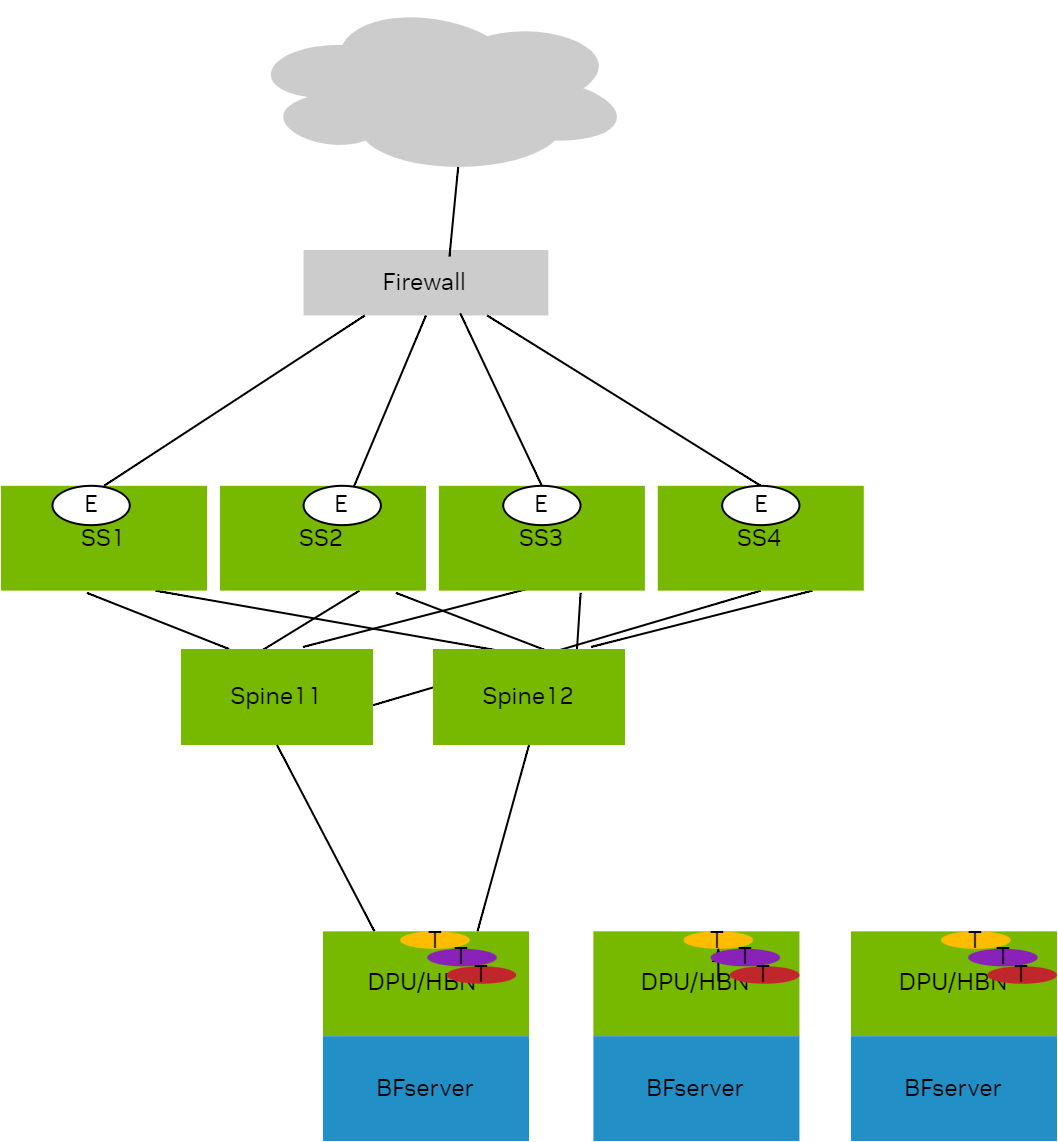
L3VNI:
|
Tenant |
L3VNI |
|
|---|---|---|
|
tenant1 |
30001 |
On HBN VTEPs |
|
tenant2 |
30002 |
On HBN VTEPs |
|
tenant3 |
30003 |
On HBN VTEPs |
|
tenant4 |
30004 |
On HBN VTEPs |
|
tenant5 |
30005 |
On HBN VTEPs |
|
tenant6 |
30006 |
On HBN VTEPs |
|
external |
60000 |
Configured on superspines and connects to external world |
On BlueField devices with HBN, every tenant VRF on HBN one must import VNI of shared external VRF:
nv set vrf tenant1 router bgp route-import from-evpn route-target ANY:60000
nv set vrf tenant1 router bgp route-import from-evpn route-target auto
nv set vrf tenant2 router bgp route-import from-evpn route-target ANY:60000
nv set vrf tenant2 router bgp route-import from-evpn route-target auto
nv set vrf tenant3 router bgp route-import from-evpn route-target ANY:60000
nv set vrf tenant3 router bgp route-import from-evpn route-target auto
nv set vrf tenant4 router bgp route-import from-evpn route-target ANY:60000
nv set vrf tenant4 router bgp route-import from-evpn route-target auto
nv set vrf tenant5 router bgp route-import from-evpn route-target ANY:60000
nv set vrf tenant5 router bgp route-import from-evpn route-target auto
nv set vrf tenant6 router bgp route-import from-evpn route-target ANY:60000
nv set vrf tenant6 router bgp route-import from-evpn route-target auto
root@doca-hbn-service-bf3-s06-1-ipmi:/tmp#
On super spine switches (SS1 in this example), every remote tenant VRF that needs access to shared services has to be leaked to the shared external VRF.
nv set vrf external router bgp route-import from-evpn route-target ANY:30001
nv set vrf external router bgp route-import from-evpn route-target ANY:30002
nv set vrf external router bgp route-import from-evpn route-target ANY:30003
nv set vrf external router bgp route-import from-evpn route-target ANY:30004
nv set vrf external router bgp route-import from-evpn route-target ANY:30005
nv set vrf external router bgp route-import from-evpn route-target ANY:30006
nv set vrf external router bgp route-import from-evpn route-target auto
root@superspine1:mgmt:/home/cumulus#
All super spines in this case need this configuration.
DVNI Leaked Routes in VRF Table of HBN
Each super spine here is advertising reachability providing 4-way overlay ECMP.
Kernel table for all tenant VRFs, showing the imported shared service:
root@doca-hbn-service-bf3-s06-1-ipmi:/tmp# ip -4 route show table all  6.0.0.4/32
6.0.0.4 table tenant1 proto bgp metric 20
	nexthop  encap ip id 60000 src 0.0.0.0 dst 6.0.0.12 ttl 0 tos 0 via 6.0.0.12 dev vxlan48 weight 1 onlink
	nexthop  encap ip id 60000 src 0.0.0.0 dst 6.0.0.13 ttl 0 tos 0 via 6.0.0.13 dev vxlan48 weight 1 onlink
	nexthop  encap ip id 60000 src 0.0.0.0 dst 6.0.0.14 ttl 0 tos 0 via 6.0.0.14 dev vxlan48 weight 1 onlink
	nexthop  encap ip id 60000 src 0.0.0.0 dst 6.0.0.15 ttl 0 tos 0 via 6.0.0.15 dev vxlan48 weight 1 onlink
6.0.0.4 table tenant2 proto bgp metric 20
	nexthop  encap ip id 60000 src 0.0.0.0 dst 6.0.0.12 ttl 0 tos 0 via 6.0.0.12 dev vxlan48 weight 1 onlink
	nexthop  encap ip id 60000 src 0.0.0.0 dst 6.0.0.13 ttl 0 tos 0 via 6.0.0.13 dev vxlan48 weight 1 onlink
	nexthop  encap ip id 60000 src 0.0.0.0 dst 6.0.0.14 ttl 0 tos 0 via 6.0.0.14 dev vxlan48 weight 1 onlink
	nexthop  encap ip id 60000 src 0.0.0.0 dst 6.0.0.15 ttl 0 tos 0 via 6.0.0.15 dev vxlan48 weight 1 onlink
6.0.0.4 table tenant3 proto bgp metric 20
	nexthop  encap ip id 60000 src 0.0.0.0 dst 6.0.0.12 ttl 0 tos 0 via 6.0.0.12 dev vxlan48 weight 1 onlink
	nexthop  encap ip id 60000 src 0.0.0.0 dst 6.0.0.13 ttl 0 tos 0 via 6.0.0.13 dev vxlan48 weight 1 onlink
	nexthop  encap ip id 60000 src 0.0.0.0 dst 6.0.0.14 ttl 0 tos 0 via 6.0.0.14 dev vxlan48 weight 1 onlink
	nexthop  encap ip id 60000 src 0.0.0.0 dst 6.0.0.15 ttl 0 tos 0 via 6.0.0.15 dev vxlan48 weight 1 onlink
6.0.0.4 table tenant4 proto bgp metric 20
	nexthop  encap ip id 60000 src 0.0.0.0 dst 6.0.0.12 ttl 0 tos 0 via 6.0.0.12 dev vxlan48 weight 1 onlink
	nexthop  encap ip id 60000 src 0.0.0.0 dst 6.0.0.13 ttl 0 tos 0 via 6.0.0.13 dev vxlan48 weight 1 onlink
	nexthop  encap ip id 60000 src 0.0.0.0 dst 6.0.0.14 ttl 0 tos 0 via 6.0.0.14 dev vxlan48 weight 1 onlink
	nexthop  encap ip id 60000 src 0.0.0.0 dst 6.0.0.15 ttl 0 tos 0 via 6.0.0.15 dev vxlan48 weight 1 onlink
6.0.0.4 table tenant5 proto bgp metric 20
	nexthop  encap ip id 60000 src 0.0.0.0 dst 6.0.0.12 ttl 0 tos 0 via 6.0.0.12 dev vxlan48 weight 1 onlink
	nexthop  encap ip id 60000 src 0.0.0.0 dst 6.0.0.13 ttl 0 tos 0 via 6.0.0.13 dev vxlan48 weight 1 onlink
	nexthop  encap ip id 60000 src 0.0.0.0 dst 6.0.0.14 ttl 0 tos 0 via 6.0.0.14 dev vxlan48 weight 1 onlink
	nexthop  encap ip id 60000 src 0.0.0.0 dst 6.0.0.15 ttl 0 tos 0 via 6.0.0.15 dev vxlan48 weight 1 onlink
6.0.0.4 table tenant6 proto bgp metric 20
	nexthop  encap ip id 60000 src 0.0.0.0 dst 6.0.0.12 ttl 0 tos 0 via 6.0.0.12 dev vxlan48 weight 1 onlink
	nexthop  encap ip id 60000 src 0.0.0.0 dst 6.0.0.13 ttl 0 tos 0 via 6.0.0.13 dev vxlan48 weight 1 onlink
	nexthop  encap ip id 60000 src 0.0.0.0 dst 6.0.0.14 ttl 0 tos 0 via 6.0.0.14 dev vxlan48 weight 1 onlink
	nexthop  encap ip id 60000 src 0.0.0.0 dst 6.0.0.15 ttl 0 tos 0 via 6.0.0.15 dev vxlan48 weight 1 onlink
root@doca-hbn-service-bf3-s06-1-ipmi:/tmp#
FRR RIB table:
root@doca-hbn-service-bf3-s06-1-ipmi:/tmp# vtysh

Hello, this is FRRouting (version 8.4.3).
Copyright 1996-2005 Kunihiro Ishiguro, et al.

doca-hbn-service-bf3-s06-1-ipmi# sh ip route vrf tenant1
Codes: K - kernel route, C - connected, S - static, R - RIP,
       O - OSPF, I - IS-IS, B - BGP, E - EIGRP, N - NHRP,
       T - Table, A - Babel, D - SHARP, F - PBR, f - OpenFabric,
       Z - FRR,
       > - selected route, * - FIB route, q - queued, r - rejected, b - backup
       t - trapped, o - offload failure

VRF tenant1:
K>* 0.0.0.0/0 [255/8192] unreachable (ICMP unreachable), 00:10:36
B>* 6.0.0.4/32 [20/0] via 6.0.0.12, vxlan48 (vrf default) onlink, label 60000, weight 1, 00:05:38
  *                   via 6.0.0.13, vxlan48 (vrf default) onlink, label 60000, weight 1, 00:05:38
  *                   via 6.0.0.14, vxlan48 (vrf default) onlink, label 60000, weight 1, 00:05:38
  *                   via 6.0.0.15, vxlan48 (vrf default) onlink, label 60000, weight 1, 00:05:38
B>* 6.6.0.12/32 [20/0] via 6.0.0.12, vxlan48 (vrf default) onlink, label 60000, weight 1, 00:05:38
B>* 6.6.0.13/32 [20/0] via 6.0.0.13, vxlan48 (vrf default) onlink, label 60000, weight 1, 00:05:38
B>* 6.6.0.14/32 [20/0] via 6.0.0.14, vxlan48 (vrf default) onlink, label 60000, weight 1, 00:05:38
B>* 6.6.0.15/32 [20/0] via 6.0.0.15, vxlan48 (vrf default) onlink, label 60000, weight 1, 00:05:38
B>* 7.1.0.6/32 [20/0] via 6.0.0.6, vlan4052_l3 onlink, weight 1, 00:05:37
C>* 7.1.0.16/32 is directly connected, tenant1, 00:10:36
B>* 7.1.0.18/32 [20/0] via 6.0.0.18, vlan4052_l3 onlink, weight 1, 00:05:37
B>* 7.1.0.20/32 [20/0] via 6.0.0.20, vlan4052_l3 onlink, weight 1, 00:05:37
C>* 21.1.0.0/16 is directly connected, vlan101, 00:10:36
C * 21.1.0.0/16 [0/1024] is directly connected, vlan101-v0, 00:10:36
C * 21.2.0.0/16 [0/1024] is directly connected, vlan102-v0, 00:10:36
C>* 21.2.0.0/16 is directly connected, vlan102, 00:10:36
B>* 101.12.4.0/24 [20/0] via 6.0.0.12, vxlan48 (vrf default) onlink, label 60000, weight 1, 00:05:38
B>* 101.13.4.0/24 [20/0] via 6.0.0.13, vxlan48 (vrf default) onlink, label 60000, weight 1, 00:05:38
B>* 101.14.4.0/24 [20/0] via 6.0.0.14, vxlan48 (vrf default) onlink, label 60000, weight 1, 00:05:38
B>* 101.15.4.0/24 [20/0] via 6.0.0.15, vxlan48 (vrf default) onlink, label 60000, weight 1, 00:05:38
doca-hbn-service-bf3-s06-1-ipmi# sh ip route vrf all
Codes: K - kernel route, C - connected, S - static, R - RIP,
       O - OSPF, I - IS-IS, B - BGP, E - EIGRP, N - NHRP,
       T - Table, A - Babel, D - SHARP, F - PBR, f - OpenFabric,
       Z - FRR,
       > - selected route, * - FIB route, q - queued, r - rejected, b - backup
       t - trapped, o - offload failure

VRF default:
B>* 6.0.0.6/32 [20/0] via fe80::202:ff:fe00:1f, p0_sf, weight 1, 00:06:47
  *                   via fe80::202:ff:fe00:27, p1_sf, weight 1, 00:06:47
B>* 6.0.0.7/32 [20/0] via fe80::202:ff:fe00:1f, p0_sf, weight 1, 00:05:48
  *                   via fe80::202:ff:fe00:27, p1_sf, weight 1, 00:05:48
B>* 6.0.0.8/32 [20/0] via fe80::202:ff:fe00:1f, p0_sf, weight 1, 00:05:38
  *                   via fe80::202:ff:fe00:27, p1_sf, weight 1, 00:05:38
B>* 6.0.0.9/32 [20/0] via fe80::202:ff:fe00:1f, p0_sf, weight 1, 00:05:28
  *                   via fe80::202:ff:fe00:27, p1_sf, weight 1, 00:05:28
B>* 6.0.0.10/32 [20/0] via fe80::202:ff:fe00:1f, p0_sf, weight 1, 00:06:49
B>* 6.0.0.11/32 [20/0] via fe80::202:ff:fe00:27, p1_sf, weight 1, 00:06:47
B>* 6.0.0.12/32 [20/0] via fe80::202:ff:fe00:1f, p0_sf, weight 1, 00:06:47
  *                    via fe80::202:ff:fe00:27, p1_sf, weight 1, 00:06:47
B>* 6.0.0.13/32 [20/0] via fe80::202:ff:fe00:1f, p0_sf, weight 1, 00:06:47
  *                    via fe80::202:ff:fe00:27, p1_sf, weight 1, 00:06:47
B>* 6.0.0.14/32 [20/0] via fe80::202:ff:fe00:1f, p0_sf, weight 1, 00:06:47
  *                    via fe80::202:ff:fe00:27, p1_sf, weight 1, 00:06:47
B>* 6.0.0.15/32 [20/0] via fe80::202:ff:fe00:1f, p0_sf, weight 1, 00:06:47
  *                    via fe80::202:ff:fe00:27, p1_sf, weight 1, 00:06:47
C>* 6.0.0.16/32 is directly connected, lo, 00:10:42
B>* 6.0.0.18/32 [20/0] via fe80::202:ff:fe00:1f, p0_sf, weight 1, 00:06:47
  *                    via fe80::202:ff:fe00:27, p1_sf, weight 1, 00:06:47
B>* 6.0.0.20/32 [20/0] via fe80::202:ff:fe00:1f, p0_sf, weight 1, 00:06:47
  *                    via fe80::202:ff:fe00:27, p1_sf, weight 1, 00:06:47
B>* 192.168.0.0/24 [20/0] via fe80::202:ff:fe00:1f, p0_sf, weight 1, 00:05:48
  *                       via fe80::202:ff:fe00:27, p1_sf, weight 1, 00:05:48

VRF internet1:
K>* 0.0.0.0/0 [255/8192] unreachable (ICMP unreachable), 00:10:42
B>* 8.1.0.6/32 [20/0] via 6.0.0.6, vlan4004_l3 onlink, weight 1, 00:05:43
C>* 8.1.0.16/32 is directly connected, internet1, 00:10:42
B>* 8.1.0.18/32 [20/0] via 6.0.0.18, vlan4004_l3 onlink, weight 1, 00:05:43
B>* 8.1.0.20/32 [20/0] via 6.0.0.20, vlan4004_l3 onlink, weight 1, 00:05:43

VRF mgmt:
K>* 0.0.0.0/0 [255/8192] unreachable (ICMP unreachable), 00:10:42
C>* 10.88.0.0/16 is directly connected, eth0, 00:10:42

VRF special1:
K>* 0.0.0.0/0 [255/8192] unreachable (ICMP unreachable), 00:10:42
B>* 9.1.0.6/32 [20/0] via 6.0.0.6, vlan4033_l3 onlink, weight 1, 00:05:43
C>* 9.1.0.16/32 is directly connected, special1, 00:10:42
B>* 9.1.0.18/32 [20/0] via 6.0.0.18, vlan4033_l3 onlink, weight 1, 00:05:43
B>* 9.1.0.20/32 [20/0] via 6.0.0.20, vlan4033_l3 onlink, weight 1, 00:05:43

VRF tenant1:
K>* 0.0.0.0/0 [255/8192] unreachable (ICMP unreachable), 00:10:42
B>* 6.0.0.4/32 [20/0] via 6.0.0.12, vxlan48 (vrf default) onlink, label 60000, weight 1, 00:05:44
  *                   via 6.0.0.13, vxlan48 (vrf default) onlink, label 60000, weight 1, 00:05:44
  *                   via 6.0.0.14, vxlan48 (vrf default) onlink, label 60000, weight 1, 00:05:44
  *                   via 6.0.0.15, vxlan48 (vrf default) onlink, label 60000, weight 1, 00:05:44
B>* 6.6.0.12/32 [20/0] via 6.0.0.12, vxlan48 (vrf default) onlink, label 60000, weight 1, 00:05:44
B>* 6.6.0.13/32 [20/0] via 6.0.0.13, vxlan48 (vrf default) onlink, label 60000, weight 1, 00:05:44
B>* 6.6.0.14/32 [20/0] via 6.0.0.14, vxlan48 (vrf default) onlink, label 60000, weight 1, 00:05:44
B>* 6.6.0.15/32 [20/0] via 6.0.0.15, vxlan48 (vrf default) onlink, label 60000, weight 1, 00:05:44
B>* 7.1.0.6/32 [20/0] via 6.0.0.6, vlan4052_l3 onlink, weight 1, 00:05:43
C>* 7.1.0.16/32 is directly connected, tenant1, 00:10:42
B>* 7.1.0.18/32 [20/0] via 6.0.0.18, vlan4052_l3 onlink, weight 1, 00:05:43
B>* 7.1.0.20/32 [20/0] via 6.0.0.20, vlan4052_l3 onlink, weight 1, 00:05:43
C>* 21.1.0.0/16 is directly connected, vlan101, 00:10:42
C * 21.1.0.0/16 [0/1024] is directly connected, vlan101-v0, 00:10:42
C * 21.2.0.0/16 [0/1024] is directly connected, vlan102-v0, 00:10:42
C>* 21.2.0.0/16 is directly connected, vlan102, 00:10:42
B>* 101.12.4.0/24 [20/0] via 6.0.0.12, vxlan48 (vrf default) onlink, label 60000, weight 1, 00:05:44
B>* 101.13.4.0/24 [20/0] via 6.0.0.13, vxlan48 (vrf default) onlink, label 60000, weight 1, 00:05:44
B>* 101.14.4.0/24 [20/0] via 6.0.0.14, vxlan48 (vrf default) onlink, label 60000, weight 1, 00:05:44
B>* 101.15.4.0/24 [20/0] via 6.0.0.15, vxlan48 (vrf default) onlink, label 60000, weight 1, 00:05:44

VRF tenant2:
K>* 0.0.0.0/0 [255/8192] unreachable (ICMP unreachable), 00:10:42
B>* 6.0.0.4/32 [20/0] via 6.0.0.12, vxlan48 (vrf default) onlink, label 60000, weight 1, 00:05:44
  *                   via 6.0.0.13, vxlan48 (vrf default) onlink, label 60000, weight 1, 00:05:44
  *                   via 6.0.0.14, vxlan48 (vrf default) onlink, label 60000, weight 1, 00:05:44
  *                   via 6.0.0.15, vxlan48 (vrf default) onlink, label 60000, weight 1, 00:05:44
B>* 6.6.0.12/32 [20/0] via 6.0.0.12, vxlan48 (vrf default) onlink, label 60000, weight 1, 00:05:44
B>* 6.6.0.13/32 [20/0] via 6.0.0.13, vxlan48 (vrf default) onlink, label 60000, weight 1, 00:05:44
B>* 6.6.0.14/32 [20/0] via 6.0.0.14, vxlan48 (vrf default) onlink, label 60000, weight 1, 00:05:44
B>* 6.6.0.15/32 [20/0] via 6.0.0.15, vxlan48 (vrf default) onlink, label 60000, weight 1, 00:05:44
B>* 7.2.0.6/32 [20/0] via 6.0.0.6, vlan4037_l3 onlink, weight 1, 00:05:43
C>* 7.2.0.16/32 is directly connected, tenant2, 00:10:42
B>* 7.2.0.18/32 [20/0] via 6.0.0.18, vlan4037_l3 onlink, weight 1, 00:05:43
B>* 7.2.0.20/32 [20/0] via 6.0.0.20, vlan4037_l3 onlink, weight 1, 00:05:43
C * 22.1.0.0/16 [0/1024] is directly connected, vlan201-v0, 00:10:42
C>* 22.1.0.0/16 is directly connected, vlan201, 00:10:42
C * 22.2.0.0/16 [0/1024] is directly connected, vlan202-v0, 00:10:42
C>* 22.2.0.0/16 is directly connected, vlan202, 00:10:42
B>* 101.12.4.0/24 [20/0] via 6.0.0.12, vxlan48 (vrf default) onlink, label 60000, weight 1, 00:05:44
B>* 101.13.4.0/24 [20/0] via 6.0.0.13, vxlan48 (vrf default) onlink, label 60000, weight 1, 00:05:44
B>* 101.14.4.0/24 [20/0] via 6.0.0.14, vxlan48 (vrf default) onlink, label 60000, weight 1, 00:05:44
B>* 101.15.4.0/24 [20/0] via 6.0.0.15, vxlan48 (vrf default) onlink, label 60000, weight 1, 00:05:44

VRF tenant3:
K>* 0.0.0.0/0 [255/8192] unreachable (ICMP unreachable), 00:10:42
B>* 6.0.0.4/32 [20/0] via 6.0.0.12, vxlan48 (vrf default) onlink, label 60000, weight 1, 00:05:44
  *                   via 6.0.0.13, vxlan48 (vrf default) onlink, label 60000, weight 1, 00:05:44
  *                   via 6.0.0.14, vxlan48 (vrf default) onlink, label 60000, weight 1, 00:05:44
  *                   via 6.0.0.15, vxlan48 (vrf default) onlink, label 60000, weight 1, 00:05:44
B>* 6.6.0.12/32 [20/0] via 6.0.0.12, vxlan48 (vrf default) onlink, label 60000, weight 1, 00:05:44
B>* 6.6.0.13/32 [20/0] via 6.0.0.13, vxlan48 (vrf default) onlink, label 60000, weight 1, 00:05:44
B>* 6.6.0.14/32 [20/0] via 6.0.0.14, vxlan48 (vrf default) onlink, label 60000, weight 1, 00:05:44
B>* 6.6.0.15/32 [20/0] via 6.0.0.15, vxlan48 (vrf default) onlink, label 60000, weight 1, 00:05:44
B>* 7.3.0.6/32 [20/0] via 6.0.0.6, vlan4022_l3 onlink, weight 1, 00:05:43
C>* 7.3.0.16/32 is directly connected, tenant3, 00:10:42
B>* 7.3.0.18/32 [20/0] via 6.0.0.18, vlan4022_l3 onlink, weight 1, 00:05:43
B>* 7.3.0.20/32 [20/0] via 6.0.0.20, vlan4022_l3 onlink, weight 1, 00:05:43
C>* 23.17.0.0/16 is directly connected, pf0vf4_sf.3, 00:10:42
B>* 23.19.0.0/16 [20/0] via 6.0.0.18, vlan4022_l3 onlink, weight 1, 00:05:43
B>* 23.21.0.0/16 [20/0] via 6.0.0.20, vlan4022_l3 onlink, weight 1, 00:05:43
B>* 101.12.4.0/24 [20/0] via 6.0.0.12, vxlan48 (vrf default) onlink, label 60000, weight 1, 00:05:44
B>* 101.13.4.0/24 [20/0] via 6.0.0.13, vxlan48 (vrf default) onlink, label 60000, weight 1, 00:05:44
B>* 101.14.4.0/24 [20/0] via 6.0.0.14, vxlan48 (vrf default) onlink, label 60000, weight 1, 00:05:44
B>* 101.15.4.0/24 [20/0] via 6.0.0.15, vxlan48 (vrf default) onlink, label 60000, weight 1, 00:05:44

VRF tenant4:
K>* 0.0.0.0/0 [255/8192] unreachable (ICMP unreachable), 00:10:42
B>* 6.0.0.4/32 [20/0] via 6.0.0.12, vxlan48 (vrf default) onlink, label 60000, weight 1, 00:05:44
  *                   via 6.0.0.13, vxlan48 (vrf default) onlink, label 60000, weight 1, 00:05:44
  *                   via 6.0.0.14, vxlan48 (vrf default) onlink, label 60000, weight 1, 00:05:44
  *                   via 6.0.0.15, vxlan48 (vrf default) onlink, label 60000, weight 1, 00:05:44
B>* 6.6.0.12/32 [20/0] via 6.0.0.12, vxlan48 (vrf default) onlink, label 60000, weight 1, 00:05:44
B>* 6.6.0.13/32 [20/0] via 6.0.0.13, vxlan48 (vrf default) onlink, label 60000, weight 1, 00:05:44
B>* 6.6.0.14/32 [20/0] via 6.0.0.14, vxlan48 (vrf default) onlink, label 60000, weight 1, 00:05:44
B>* 6.6.0.15/32 [20/0] via 6.0.0.15, vxlan48 (vrf default) onlink, label 60000, weight 1, 00:05:44
B>* 7.4.0.6/32 [20/0] via 6.0.0.6, vlan4017_l3 onlink, weight 1, 00:05:43
C>* 7.4.0.16/32 is directly connected, tenant4, 00:10:42
B>* 7.4.0.18/32 [20/0] via 6.0.0.18, vlan4017_l3 onlink, weight 1, 00:05:43
B>* 7.4.0.20/32 [20/0] via 6.0.0.20, vlan4017_l3 onlink, weight 1, 00:05:43
C>* 24.17.0.0/16 is directly connected, pf0vf4_sf.4, 00:10:42
B>* 24.19.0.0/16 [20/0] via 6.0.0.18, vlan4017_l3 onlink, weight 1, 00:05:43
B>* 24.21.0.0/16 [20/0] via 6.0.0.20, vlan4017_l3 onlink, weight 1, 00:05:43
B>* 101.12.4.0/24 [20/0] via 6.0.0.12, vxlan48 (vrf default) onlink, label 60000, weight 1, 00:05:44
B>* 101.13.4.0/24 [20/0] via 6.0.0.13, vxlan48 (vrf default) onlink, label 60000, weight 1, 00:05:44
B>* 101.14.4.0/24 [20/0] via 6.0.0.14, vxlan48 (vrf default) onlink, label 60000, weight 1, 00:05:44
B>* 101.15.4.0/24 [20/0] via 6.0.0.15, vxlan48 (vrf default) onlink, label 60000, weight 1, 00:05:44

VRF tenant5:
K>* 0.0.0.0/0 [255/8192] unreachable (ICMP unreachable), 00:10:42
B>* 6.0.0.4/32 [20/0] via 6.0.0.12, vxlan48 (vrf default) onlink, label 60000, weight 1, 00:05:44
  *                   via 6.0.0.13, vxlan48 (vrf default) onlink, label 60000, weight 1, 00:05:44
  *                   via 6.0.0.14, vxlan48 (vrf default) onlink, label 60000, weight 1, 00:05:44
  *                   via 6.0.0.15, vxlan48 (vrf default) onlink, label 60000, weight 1, 00:05:44
B>* 6.6.0.12/32 [20/0] via 6.0.0.12, vxlan48 (vrf default) onlink, label 60000, weight 1, 00:05:44
B>* 6.6.0.13/32 [20/0] via 6.0.0.13, vxlan48 (vrf default) onlink, label 60000, weight 1, 00:05:44
B>* 6.6.0.14/32 [20/0] via 6.0.0.14, vxlan48 (vrf default) onlink, label 60000, weight 1, 00:05:44
B>* 6.6.0.15/32 [20/0] via 6.0.0.15, vxlan48 (vrf default) onlink, label 60000, weight 1, 00:05:44
B>* 7.5.0.6/32 [20/0] via 6.0.0.6, vlan4046_l3 onlink, weight 1, 00:05:43
C>* 7.5.0.16/32 is directly connected, tenant5, 00:10:42
B>* 7.5.0.18/32 [20/0] via 6.0.0.18, vlan4046_l3 onlink, weight 1, 00:05:43
B>* 7.5.0.20/32 [20/0] via 6.0.0.20, vlan4046_l3 onlink, weight 1, 00:05:43
C>* 25.17.0.0/16 is directly connected, pf0vf4_sf.5, 00:10:42
B>* 25.19.0.0/16 [20/0] via 6.0.0.18, vlan4046_l3 onlink, weight 1, 00:05:43
B>* 25.21.0.0/16 [20/0] via 6.0.0.20, vlan4046_l3 onlink, weight 1, 00:05:43
B>* 101.12.4.0/24 [20/0] via 6.0.0.12, vxlan48 (vrf default) onlink, label 60000, weight 1, 00:05:44
B>* 101.13.4.0/24 [20/0] via 6.0.0.13, vxlan48 (vrf default) onlink, label 60000, weight 1, 00:05:44
B>* 101.14.4.0/24 [20/0] via 6.0.0.14, vxlan48 (vrf default) onlink, label 60000, weight 1, 00:05:44
B>* 101.15.4.0/24 [20/0] via 6.0.0.15, vxlan48 (vrf default) onlink, label 60000, weight 1, 00:05:44

VRF tenant6:
K>* 0.0.0.0/0 [255/8192] unreachable (ICMP unreachable), 00:10:42
B>* 6.0.0.4/32 [20/0] via 6.0.0.12, vxlan48 (vrf default) onlink, label 60000, weight 1, 00:05:44
  *                   via 6.0.0.13, vxlan48 (vrf default) onlink, label 60000, weight 1, 00:05:44
  *                   via 6.0.0.14, vxlan48 (vrf default) onlink, label 60000, weight 1, 00:05:44
  *                   via 6.0.0.15, vxlan48 (vrf default) onlink, label 60000, weight 1, 00:05:44
B>* 6.6.0.12/32 [20/0] via 6.0.0.12, vxlan48 (vrf default) onlink, label 60000, weight 1, 00:05:44
B>* 6.6.0.13/32 [20/0] via 6.0.0.13, vxlan48 (vrf default) onlink, label 60000, weight 1, 00:05:44
B>* 6.6.0.14/32 [20/0] via 6.0.0.14, vxlan48 (vrf default) onlink, label 60000, weight 1, 00:05:44
B>* 6.6.0.15/32 [20/0] via 6.0.0.15, vxlan48 (vrf default) onlink, label 60000, weight 1, 00:05:44
B>* 7.6.0.6/32 [20/0] via 6.0.0.6, vlan4041_l3 onlink, weight 1, 00:05:43
C>* 7.6.0.16/32 is directly connected, tenant6, 00:10:42
B>* 7.6.0.18/32 [20/0] via 6.0.0.18, vlan4041_l3 onlink, weight 1, 00:05:43
B>* 7.6.0.20/32 [20/0] via 6.0.0.20, vlan4041_l3 onlink, weight 1, 00:05:43
C>* 26.17.0.0/16 is directly connected, pf0vf4_sf.6, 00:10:42
B>* 26.19.0.0/16 [20/0] via 6.0.0.18, vlan4041_l3 onlink, weight 1, 00:05:43
B>* 26.21.0.0/16 [20/0] via 6.0.0.20, vlan4041_l3 onlink, weight 1, 00:05:43
B>* 101.12.4.0/24 [20/0] via 6.0.0.12, vxlan48 (vrf default) onlink, label 60000, weight 1, 00:05:44
B>* 101.13.4.0/24 [20/0] via 6.0.0.13, vxlan48 (vrf default) onlink, label 60000, weight 1, 00:05:44
B>* 101.14.4.0/24 [20/0] via 6.0.0.14, vxlan48 (vrf default) onlink, label 60000, weight 1, 00:05:44
B>* 101.15.4.0/24 [20/0] via 6.0.0.15, vxlan48 (vrf default) onlink, label 60000, weight 1, 00:05:44
doca-hbn-service-bf3-s06-1-ipmi#
DVNI Debugging
BGP/Zebra debug:
May  7 20:59:49 doca-hbn-service-bf3-s06-1-ipmi bgpd[1775018]: [GKC5Y-XBAX9] vrf tenant1: import evpn prefix [5]:[0]:[32]:[6.0.0.4] parent 0xaaaafda63a90 flags 0x410
May  7 20:59:49 doca-hbn-service-bf3-s06-1-ipmi bgpd[1775018]: [KZNVF-SX7KT] ... new pi dest 0xaaaafe524650 (l 2) pi 0xaaaafe5ae400 (l 1, f 0x4010)
May  7 20:59:49 doca-hbn-service-bf3-s06-1-ipmi bgpd[1775018]: [GKC5Y-XBAX9] vrf tenant2: import evpn prefix [5]:[0]:[32]:[6.0.0.4] parent 0xaaaafda63a90 flags 0x410
May  7 20:59:49 doca-hbn-service-bf3-s06-1-ipmi bgpd[1775018]: [KZNVF-SX7KT] ... new pi dest 0xaaaafe51c420 (l 2) pi 0xaaaafe55d230 (l 1, f 0x4010)
May  7 20:59:49 doca-hbn-service-bf3-s06-1-ipmi bgpd[1775018]: [GKC5Y-XBAX9] vrf tenant3: import evpn prefix [5]:[0]:[32]:[6.0.0.4] parent 0xaaaafda63a90 flags 0x410
May  7 20:59:49 doca-hbn-service-bf3-s06-1-ipmi bgpd[1775018]: [KZNVF-SX7KT] ... new pi dest 0xaaaafe51a670 (l 2) pi 0xaaaafe674820 (l 1, f 0x4010)
May  7 20:59:49 doca-hbn-service-bf3-s06-1-ipmi bgpd[1775018]: [GKC5Y-XBAX9] vrf tenant4: import evpn prefix [5]:[0]:[32]:[6.0.0.4] parent 0xaaaafda63a90 flags 0x410
May  7 20:59:49 doca-hbn-service-bf3-s06-1-ipmi bgpd[1775018]: [KZNVF-SX7KT] ... new pi dest 0xaaaafe519fb0 (l 2) pi 0xaaaafe675e40 (l 1, f 0x4010)
May  7 20:59:49 doca-hbn-service-bf3-s06-1-ipmi bgpd[1775018]: [GKC5Y-XBAX9] vrf tenant5: import evpn prefix [5]:[0]:[32]:[6.0.0.4] parent 0xaaaafda63a90 flags 0x410
May  7 20:59:49 doca-hbn-service-bf3-s06-1-ipmi bgpd[1775018]: [KZNVF-SX7KT] ... new pi dest 0xaaaafe55ae50 (l 2) pi 0xaaaafe5482f0 (l 1, f 0x4010)
May  7 20:59:49 doca-hbn-service-bf3-s06-1-ipmi bgpd[1775018]: [GKC5Y-XBAX9] vrf tenant6: import evpn prefix [5]:[0]:[32]:[6.0.0.4] parent 0xaaaafda63a90 flags 0x410
May  7 20:59:49 doca-hbn-service-bf3-s06-1-ipmi bgpd[1775018]: [KZNVF-SX7KT] ... new pi dest 0xaaaafdaf3590 (l 2) pi 0xaaaafe48fbf0 (l 1, f 0x4010)
DVNI table:
root@doca-hbn-service-bf3-s06-1-ipmi:/tmp# cat /cumulus/nl2docad/run/software-tables/15
{
  "table": {
    "id": 15,
    "name": "HAL Downstream-VNI Table ",
    "count": 1,
    "records": [
    {
      "vni": 60000,
      "fid": 4098,
      "mark-for-del": 0,
      "vtep-users":
      {
        "count": 4,
        "vtep-user-list": [
          {
            "dest-vtep": "6.0.0.12",
            "dest-mac": "44:38:39:f0:00:12",
            "is-dmac-null": 0,
            "ref-cnt": 36
          },
          {
            "dest-vtep": "6.0.0.14",
            "dest-mac": "44:38:39:f0:00:14",
            "is-dmac-null": 0,
            "ref-cnt": 36
          },
          {
            "dest-vtep": "6.0.0.13",
            "dest-mac": "44:38:39:f0:00:13",
            "is-dmac-null": 0,
            "ref-cnt": 36
          },
          {
            "dest-vtep": "6.0.0.15",
            "dest-mac": "44:38:39:f0:00:15",
            "is-dmac-null": 0,
            "ref-cnt": 36
          }
        ]
      }
    }
   ]
  }
}root@doca-hbn-service-bf3-s06-1-ipmi:/tmp#
Sample DVNI Configuration
HBN configuration example for BlueField devices:
root@doca-hbn-service-bf3-s06-1-ipmi:/tmp# nv config show -o commands
nv set bridge domain br_default vlan 101 vni 10101
nv set bridge domain br_default vlan 102 vni 10102
nv set bridge domain br_default vlan 201 vni 10201
nv set bridge domain br_default vlan 202 vni 10202
nv set evpn enable on
nv set evpn route-advertise svi-ip off
nv set interface ilan3200 ip vrf internet1
nv set interface ilan3200 vlan 3200
nv set interface ilan3200,slan3201,vlan101-102,201-202,3001-3006 base-interface br_default
nv set interface ilan3200,slan3201,vlan101-102,201-202,3001-3006 type svi
nv set interface lo ip address 6.0.0.16/32
nv set interface lo ip address 2001::16/128
nv set interface lo type loopback
nv set interface p0_sf,p1_sf,pf0hpf_sf,pf0vf0_sf,pf0vf1_sf,pf0vf2_sf,pf0vf3_sf,pf0vf4_sf,pf0vf5_sf,pf0vf6_sf,pf0vf7_sf,pf0vf8_sf,pf0vf9_sf,pf1hpf_sf,pf1vf0_sf,pf1vf1_sf type swp
nv set interface pf0vf0_sf bridge domain br_default access 101
nv set interface pf0vf1_sf bridge domain br_default access 102
nv set interface pf0vf2_sf bridge domain br_default access 201
nv set interface pf0vf3_sf bridge domain br_default access 202
nv set interface pf0vf4_sf.3 ip address 23.17.0.16/16
nv set interface pf0vf4_sf.3 ip address 2020:0:3:17::16/64
nv set interface pf0vf4_sf.3 vlan 3
nv set interface pf0vf4_sf.3,vlan3003 ip vrf tenant3
nv set interface pf0vf4_sf.3-6 base-interface pf0vf4_sf
nv set interface pf0vf4_sf.3-6 type sub
nv set interface pf0vf4_sf.4 ip address 24.17.0.16/16
nv set interface pf0vf4_sf.4 ip address 2020:0:4:17::16/64
nv set interface pf0vf4_sf.4 vlan 4
nv set interface pf0vf4_sf.4,vlan3004 ip vrf tenant4
nv set interface pf0vf4_sf.5 ip address 25.17.0.16/16
nv set interface pf0vf4_sf.5 ip address 2020:0:5:17::16/64
nv set interface pf0vf4_sf.5 vlan 5
nv set interface pf0vf4_sf.5,vlan3005 ip vrf tenant5
nv set interface pf0vf4_sf.6 ip address 26.17.0.16/16
nv set interface pf0vf4_sf.6 ip address 2020:0:6:17::16/64
nv set interface pf0vf4_sf.6 vlan 6
nv set interface pf0vf4_sf.6,vlan3006 ip vrf tenant6
nv set interface slan3201 ip vrf special1
nv set interface slan3201 vlan 3201
nv set interface vlan101 ip address 21.1.0.16/16
nv set interface vlan101 ip address 2020:0:1:1::16/64
nv set interface vlan101 ip vrr address 21.1.0.250/16
nv set interface vlan101 ip vrr address 2020:0:1:1::250/64
nv set interface vlan101 ip vrr mac-address 00:00:01:00:00:65
nv set interface vlan101 vlan 101
nv set interface vlan101-102,201-202 ip vrr enable on
nv set interface vlan101-102,3001 ip vrf tenant1
nv set interface vlan102 ip address 21.2.0.16/16
nv set interface vlan102 ip address 2020:0:1:2::16/64
nv set interface vlan102 ip vrr address 21.2.0.250/16
nv set interface vlan102 ip vrr address 2020:0:1:2::250/64
nv set interface vlan102 ip vrr mac-address 00:00:01:00:00:66
nv set interface vlan102 vlan 102
nv set interface vlan201 ip address 22.1.0.16/16
nv set interface vlan201 ip address 2020:0:2:1::16/64
nv set interface vlan201 ip vrr address 22.1.0.250/16
nv set interface vlan201 ip vrr address 2020:0:2:1::250/64
nv set interface vlan201 ip vrr mac-address 00:00:02:00:00:c9
nv set interface vlan201 vlan 201
nv set interface vlan201-202,3002 ip vrf tenant2
nv set interface vlan202 ip address 22.2.0.16/16
nv set interface vlan202 ip address 2020:0:2:2::16/64
nv set interface vlan202 ip vrr address 22.2.0.250/16
nv set interface vlan202 ip vrr address 2020:0:2:2::250/64
nv set interface vlan202 ip vrr mac-address 00:00:02:00:00:ca
nv set interface vlan202 vlan 202
nv set interface vlan3001 vlan 3001
nv set interface vlan3002 vlan 3002
nv set interface vlan3003 vlan 3003
nv set interface vlan3004 vlan 3004
nv set interface vlan3005 vlan 3005
nv set interface vlan3006 vlan 3006
nv set nve vxlan arp-nd-suppress on
nv set nve vxlan enable on
nv set nve vxlan source address 6.0.0.16
nv set platform
nv set router bgp autonomous-system 65011
nv set router bgp enable on
nv set router bgp router-id 6.0.0.16
nv set router vrr enable on
nv set system config snippet
nv set system global
nv set vrf default router bgp address-family ipv4-unicast enable on
nv set vrf default router bgp address-family ipv4-unicast redistribute connected enable on
nv set vrf default router bgp address-family ipv6-unicast enable on
nv set vrf default router bgp address-family l2vpn-evpn enable on
nv set vrf default router bgp enable on
nv set vrf default router bgp neighbor 6.0.0.7 peer-group rservers
nv set vrf default router bgp neighbor 6.0.0.7 type numbered
nv set vrf default router bgp neighbor 6.0.0.8 peer-group rservers
nv set vrf default router bgp neighbor 6.0.0.8 type numbered
nv set vrf default router bgp neighbor 6.0.0.9 peer-group rservers
nv set vrf default router bgp neighbor 6.0.0.9 type numbered
nv set vrf default router bgp neighbor p0_sf peer-group fabric
nv set vrf default router bgp neighbor p0_sf type unnumbered
nv set vrf default router bgp neighbor p1_sf peer-group fabric
nv set vrf default router bgp neighbor p1_sf type unnumbered
nv set vrf default router bgp peer-group fabric address-family ipv4-unicast enable on
nv set vrf default router bgp peer-group fabric address-family ipv6-unicast enable on
nv set vrf default router bgp peer-group fabric bfd detect-multiplier 3
nv set vrf default router bgp peer-group fabric bfd enable on
nv set vrf default router bgp peer-group fabric bfd min-rx-interval 1000
nv set vrf default router bgp peer-group fabric bfd min-tx-interval 1000
nv set vrf default router bgp peer-group fabric remote-as external
nv set vrf default router bgp peer-group rservers address-family ipv4-unicast enable off
nv set vrf default router bgp peer-group rservers address-family l2vpn-evpn add-path-tx off
nv set vrf default router bgp peer-group rservers address-family l2vpn-evpn enable on
nv set vrf default router bgp peer-group rservers multihop-ttl 10
nv set vrf default router bgp peer-group rservers remote-as external
nv set vrf default router bgp peer-group rservers update-source lo
nv set vrf internet1 evpn enable on
nv set vrf internet1 evpn vni 42000
nv set vrf internet1 loopback ip address 8.1.0.16/32
nv set vrf internet1 loopback ip address 2008:0:1::16/64
nv set vrf internet1 router bgp address-family ipv4-unicast enable on
nv set vrf internet1 router bgp address-family ipv4-unicast redistribute connected enable on
nv set vrf internet1 router bgp address-family ipv4-unicast route-export to-evpn enable on
nv set vrf internet1 router bgp address-family ipv6-unicast enable on
nv set vrf internet1 router bgp address-family ipv6-unicast redistribute connected enable on
nv set vrf internet1 router bgp address-family ipv6-unicast route-export to-evpn enable on
nv set vrf internet1 router bgp enable on
nv set vrf special1 evpn enable on
nv set vrf special1 evpn vni 42001
nv set vrf special1 loopback ip address 9.1.0.16/32
nv set vrf special1 loopback ip address 2009:0:1::16/64
nv set vrf special1 router bgp address-family ipv4-unicast enable on
nv set vrf special1 router bgp address-family ipv4-unicast redistribute connected enable on
nv set vrf special1 router bgp address-family ipv4-unicast route-export to-evpn enable on
nv set vrf special1 router bgp address-family ipv6-unicast enable on
nv set vrf special1 router bgp address-family ipv6-unicast redistribute connected enable on
nv set vrf special1 router bgp address-family ipv6-unicast route-export to-evpn enable on
nv set vrf special1 router bgp enable on
nv set vrf tenant1 evpn enable on
nv set vrf tenant1 evpn vni 30001
nv set vrf tenant1 loopback ip address 7.1.0.16/32
nv set vrf tenant1 loopback ip address 2007:0:1::16/64
nv set vrf tenant1 router bgp address-family ipv4-unicast enable on
nv set vrf tenant1 router bgp address-family ipv4-unicast redistribute connected enable on
nv set vrf tenant1 router bgp address-family ipv4-unicast route-export to-evpn enable on
nv set vrf tenant1 router bgp address-family ipv6-unicast enable on
nv set vrf tenant1 router bgp address-family ipv6-unicast redistribute connected enable on
nv set vrf tenant1 router bgp address-family ipv6-unicast route-export to-evpn enable on
nv set vrf tenant1 router bgp enable on
nv set vrf tenant1 router bgp neighbor 21.1.0.17 peer-group hostgroup
nv set vrf tenant1 router bgp neighbor 21.1.0.17 type numbered
nv set vrf tenant1 router bgp peer-group hostgroup address-family ipv4-unicast enable on
nv set vrf tenant1 router bgp peer-group hostgroup address-family ipv6-unicast enable on
nv set vrf tenant1 router bgp peer-group hostgroup remote-as external
nv set vrf tenant1 router bgp route-import from-evpn route-target ANY:60000
nv set vrf tenant1 router bgp route-import from-evpn route-target auto
nv set vrf tenant1 router bgp router-id 6.0.0.16
nv set vrf tenant2 evpn enable on
nv set vrf tenant2 evpn vni 30002
nv set vrf tenant2 loopback ip address 7.2.0.16/32
nv set vrf tenant2 loopback ip address 2007:0:2::16/64
nv set vrf tenant2 router bgp address-family ipv4-unicast enable on
nv set vrf tenant2 router bgp address-family ipv4-unicast redistribute connected enable on
nv set vrf tenant2 router bgp address-family ipv4-unicast route-export to-evpn enable on
nv set vrf tenant2 router bgp address-family ipv6-unicast enable on
nv set vrf tenant2 router bgp address-family ipv6-unicast redistribute connected enable on
nv set vrf tenant2 router bgp address-family ipv6-unicast route-export to-evpn enable on
nv set vrf tenant2 router bgp enable on
nv set vrf tenant2 router bgp neighbor 22.1.0.17 peer-group hostgroup
nv set vrf tenant2 router bgp neighbor 22.1.0.17 type numbered
nv set vrf tenant2 router bgp peer-group hostgroup address-family ipv4-unicast enable on
nv set vrf tenant2 router bgp peer-group hostgroup address-family ipv6-unicast enable on
nv set vrf tenant2 router bgp peer-group hostgroup remote-as external
nv set vrf tenant2 router bgp route-import from-evpn route-target ANY:60000
nv set vrf tenant2 router bgp route-import from-evpn route-target auto
nv set vrf tenant2 router bgp router-id 6.0.0.16
nv set vrf tenant3 evpn enable on
nv set vrf tenant3 evpn vni 30003
nv set vrf tenant3 loopback ip address 7.3.0.16/32
nv set vrf tenant3 loopback ip address 2007:0:3::16/64
nv set vrf tenant3 router bgp address-family ipv4-unicast enable on
nv set vrf tenant3 router bgp address-family ipv4-unicast redistribute connected enable on
nv set vrf tenant3 router bgp address-family ipv4-unicast route-export to-evpn enable on
nv set vrf tenant3 router bgp address-family ipv6-unicast enable on
nv set vrf tenant3 router bgp address-family ipv6-unicast redistribute connected enable on
nv set vrf tenant3 router bgp address-family ipv6-unicast route-export to-evpn enable on
nv set vrf tenant3 router bgp enable on
nv set vrf tenant3 router bgp neighbor 23.17.0.17 peer-group hostgroup
nv set vrf tenant3 router bgp neighbor 23.17.0.17 type numbered
nv set vrf tenant3 router bgp peer-group hostgroup address-family ipv4-unicast enable on
nv set vrf tenant3 router bgp peer-group hostgroup address-family ipv6-unicast enable on
nv set vrf tenant3 router bgp peer-group hostgroup remote-as external
nv set vrf tenant3 router bgp route-import from-evpn route-target ANY:60000
nv set vrf tenant3 router bgp route-import from-evpn route-target auto
nv set vrf tenant3 router bgp router-id 6.0.0.16
nv set vrf tenant3 table auto
nv set vrf tenant4 evpn enable on
nv set vrf tenant4 evpn vni 30004
nv set vrf tenant4 loopback ip address 7.4.0.16/32
nv set vrf tenant4 loopback ip address 2007:0:4::16/64
nv set vrf tenant4 router bgp address-family ipv4-unicast enable on
nv set vrf tenant4 router bgp address-family ipv4-unicast redistribute connected enable on
nv set vrf tenant4 router bgp address-family ipv4-unicast route-export to-evpn enable on
nv set vrf tenant4 router bgp address-family ipv6-unicast enable on
nv set vrf tenant4 router bgp address-family ipv6-unicast redistribute connected enable on
nv set vrf tenant4 router bgp address-family ipv6-unicast route-export to-evpn enable on
nv set vrf tenant4 router bgp enable on
nv set vrf tenant4 router bgp neighbor 24.17.0.17 peer-group hostgroup
nv set vrf tenant4 router bgp neighbor 24.17.0.17 type numbered
nv set vrf tenant4 router bgp peer-group hostgroup address-family ipv4-unicast enable on
nv set vrf tenant4 router bgp peer-group hostgroup address-family ipv6-unicast enable on
nv set vrf tenant4 router bgp peer-group hostgroup remote-as external
nv set vrf tenant4 router bgp route-import from-evpn route-target ANY:60000
nv set vrf tenant4 router bgp route-import from-evpn route-target auto
nv set vrf tenant4 router bgp router-id 6.0.0.16
nv set vrf tenant4 table auto
nv set vrf tenant5 evpn enable on
nv set vrf tenant5 evpn vni 30005
nv set vrf tenant5 loopback ip address 7.5.0.16/32
nv set vrf tenant5 loopback ip address 2007:0:5::16/64
nv set vrf tenant5 router bgp address-family ipv4-unicast enable on
nv set vrf tenant5 router bgp address-family ipv4-unicast redistribute connected enable on
nv set vrf tenant5 router bgp address-family ipv4-unicast route-export to-evpn enable on
nv set vrf tenant5 router bgp address-family ipv6-unicast enable on
nv set vrf tenant5 router bgp address-family ipv6-unicast redistribute connected enable on
nv set vrf tenant5 router bgp address-family ipv6-unicast route-export to-evpn enable on
nv set vrf tenant5 router bgp enable on
nv set vrf tenant5 router bgp neighbor 25.17.0.17 peer-group hostgroup
nv set vrf tenant5 router bgp neighbor 25.17.0.17 type numbered
nv set vrf tenant5 router bgp peer-group hostgroup address-family ipv4-unicast enable on
nv set vrf tenant5 router bgp peer-group hostgroup address-family ipv6-unicast enable on
nv set vrf tenant5 router bgp peer-group hostgroup remote-as external
nv set vrf tenant5 router bgp route-import from-evpn route-target ANY:60000
nv set vrf tenant5 router bgp route-import from-evpn route-target auto
nv set vrf tenant5 router bgp router-id 6.0.0.16
nv set vrf tenant5 table auto
nv set vrf tenant6 evpn enable on
nv set vrf tenant6 evpn vni 30006
nv set vrf tenant6 loopback ip address 7.6.0.16/32
nv set vrf tenant6 loopback ip address 2007:0:6::16/64
nv set vrf tenant6 router bgp address-family ipv4-unicast enable on
nv set vrf tenant6 router bgp address-family ipv4-unicast redistribute connected enable on
nv set vrf tenant6 router bgp address-family ipv4-unicast route-export to-evpn enable on
nv set vrf tenant6 router bgp address-family ipv6-unicast enable on
nv set vrf tenant6 router bgp address-family ipv6-unicast redistribute connected enable on
nv set vrf tenant6 router bgp address-family ipv6-unicast route-export to-evpn enable on
nv set vrf tenant6 router bgp enable on
nv set vrf tenant6 router bgp neighbor 26.17.0.17 peer-group hostgroup
nv set vrf tenant6 router bgp neighbor 26.17.0.17 type numbered
nv set vrf tenant6 router bgp peer-group hostgroup address-family ipv4-unicast enable on
nv set vrf tenant6 router bgp peer-group hostgroup address-family ipv6-unicast enable on
nv set vrf tenant6 router bgp peer-group hostgroup remote-as external
nv set vrf tenant6 router bgp route-import from-evpn route-target ANY:60000
nv set vrf tenant6 router bgp route-import from-evpn route-target auto
nv set vrf tenant6 router bgp router-id 6.0.0.16
nv set vrf tenant6 table auto
root@doca-hbn-service-bf3-s06-1-ipmi:/tmp#
SS1 switch configuration example:
root@superspine1:mgmt:/home/cumulus# nv config show -o commands
nv set bridge domain br_default vlan 101 vni 10101
nv set bridge domain br_default vlan 102 vni 10102
nv set bridge domain br_default vlan 201 vni 10201
nv set bridge domain br_default vlan 202 vni 10202
nv set evpn enable on
nv set interface eth0 ip address 192.168.0.15/24
nv set interface eth0 ip gateway 192.168.0.2
nv set interface eth0 type eth
nv set interface lo ip address 6.0.0.12/32
nv set interface lo ip address 2001::12/128
nv set interface lo type loopback
nv set interface swp1-6 type swp
nv set interface swp6 ip address 101.12.4.12/24
nv set interface swp6 ip address 2101:12::4:12/112
nv set interface swp6 ip vrf external
nv set nve vxlan arp-nd-suppress on
nv set nve vxlan enable on
nv set nve vxlan source address 6.0.0.12
nv set platform
nv set router bgp autonomous-system 65300
nv set router bgp enable on
nv set router bgp router-id 6.0.0.12
nv set system config snippet
nv set system global system-mac 44:38:39:f0:00:12
nv set system hostname superspine1
nv set system ssh-server permit-root-login enabled
nv set vrf default router bgp address-family ipv4-unicast enable on
nv set vrf default router bgp address-family ipv4-unicast redistribute connected enable on
nv set vrf default router bgp address-family ipv6-unicast enable on
nv set vrf default router bgp address-family l2vpn-evpn enable on
nv set vrf default router bgp enable on
nv set vrf default router bgp neighbor swp1 peer-group fabric
nv set vrf default router bgp neighbor swp1 type unnumbered
nv set vrf default router bgp neighbor swp2 peer-group fabric
nv set vrf default router bgp neighbor swp2 type unnumbered
nv set vrf default router bgp neighbor swp3 peer-group rservers
nv set vrf default router bgp neighbor swp3 type unnumbered
nv set vrf default router bgp neighbor swp4 peer-group rservers
nv set vrf default router bgp neighbor swp4 type unnumbered
nv set vrf default router bgp neighbor swp5 peer-group rservers
nv set vrf default router bgp neighbor swp5 type unnumbered
nv set vrf default router bgp peer-group fabric address-family ipv4-unicast enable on
nv set vrf default router bgp peer-group fabric address-family ipv6-unicast enable on
nv set vrf default router bgp peer-group fabric bfd detect-multiplier 3
nv set vrf default router bgp peer-group fabric bfd enable on
nv set vrf default router bgp peer-group fabric bfd min-rx-interval 1000
nv set vrf default router bgp peer-group fabric bfd min-tx-interval 1000
nv set vrf default router bgp peer-group fabric remote-as external
nv set vrf default router bgp peer-group rservers address-family ipv4-unicast enable on
nv set vrf default router bgp peer-group rservers address-family l2vpn-evpn add-path-tx off
nv set vrf default router bgp peer-group rservers address-family l2vpn-evpn enable on
nv set vrf default router bgp peer-group rservers remote-as external
nv set vrf external evpn enable on
nv set vrf external evpn vni 60000
nv set vrf external loopback ip address 6.6.0.12/32
nv set vrf external loopback ip address 2006:0:6::12/64
nv set vrf external router bgp address-family ipv4-unicast enable on
nv set vrf external router bgp address-family ipv4-unicast redistribute connected enable on
nv set vrf external router bgp address-family ipv4-unicast route-export to-evpn enable on
nv set vrf external router bgp address-family ipv6-unicast enable on
nv set vrf external router bgp address-family ipv6-unicast redistribute connected enable on
nv set vrf external router bgp address-family ipv6-unicast route-export to-evpn enable on
nv set vrf external router bgp address-family l2vpn-evpn enable on
nv set vrf external router bgp enable on
nv set vrf external router bgp neighbor swp6 peer-group peer-group-fw
nv set vrf external router bgp neighbor swp6 type unnumbered
nv set vrf external router bgp peer-group peer-group-fw address-family ipv4-unicast enable on
nv set vrf external router bgp peer-group peer-group-fw address-family ipv6-unicast enable on
nv set vrf external router bgp peer-group peer-group-fw remote-as external
nv set vrf external router bgp route-import from-evpn route-target ANY:30001
nv set vrf external router bgp route-import from-evpn route-target ANY:30002
nv set vrf external router bgp route-import from-evpn route-target ANY:30003
nv set vrf external router bgp route-import from-evpn route-target ANY:30004
nv set vrf external router bgp route-import from-evpn route-target ANY:30005
nv set vrf external router bgp route-import from-evpn route-target ANY:30006
nv set vrf external router bgp route-import from-evpn route-target auto
root@superspine1:mgmt:/home/cumulus#
Gateway Application Using Downstream VNI and Subinterface
A DPU running the HBN service can be deployed in the role of a border gateway using a combination of HBN features, specifically, EVPN symmetric routing, downstream VNI, VRF route-leaking, and VLAN sub-interfaces. Such a border gateway can do the northbound traffic handoff (to external networks or the Internet) for one or more tenants. In this gateway configuration, the BlueField's uplinks must carry both the tenant traffic which would be in the "overlay" and VXLAN-encapsulated, as well as traffic to and from the external network or Internet, which would be direct-routed in the "underlay". This is accomplished by configuring and running VXLAN-EVPN on the uplink interfaces while configuring and using additional VLAN sub-interfaces on those same uplinks for the traffic to and from external networks. These VLAN sub-interfaces would be configured into an Internet or external VRF for separation from the VXLAN-encapsulated traffic which is carried over the default VRF.
With a BlueField running HBN able to act as a border gateway, there is no longer a dependence on physical switches and routers to terminate VXLAN traffic and perform this role, hence the requirements on the underlying network is simply to provide end-to-end IP/UDP connectivity and facilitate the setup of overlay networks on top. Additionally, multiple border gateways can be easily deployed in the network, including dedicated gateways per tenant or shared gateways for groups of tenants.
Since HBN currently does not support network address translation (NAT), a dedicated border gateway must be deployed per tenant, for those tenants that have overlapping IP addresses.
For more details and configuration of some of the key features that together enable the border gateway functionality, refer to sections on Downstream VNIs and NVIDIA DOCA HBN Service Guide | id (2.7.0)NVIDIADOCAHBNServiceGuide VLANSubinterfaces.
Gateway Application Example
The following topology diagram and associated configuration snippets show two different use cases of border gateway deployment:
-
tenant1is an example of a tenant hosted on a server(s) with a non-gateway BlueField, using a dedicated border gateway on BlueField Gw-HBN1 for Internet connectivity. Traffic flow to and from the Internet for this tenant is marked in pink. -
gw_tenant1is an example of a tenant hosted on a server(s) with a gateway BlueField. In this case, the border gateway for this tenant is provided by BlueField Gw-HBN2. Traffic flow to and from the Internet for this tenant is depicted in blue.
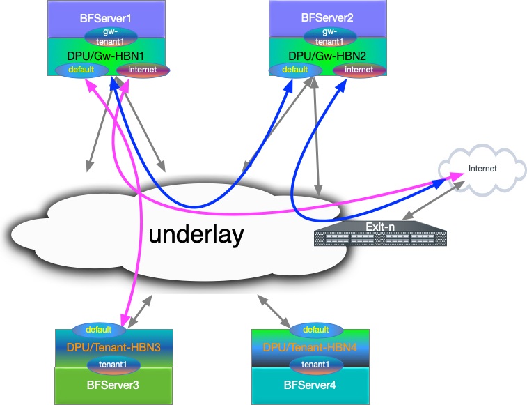
L3 VNI Origin Map
|
HBN |
VRF |
L3 VNI |
|---|---|---|
|
|
|
|
|
|
|
|
|
|
|
|
Configuration Snippet for Internet VRF
-
Internet VRF is established in BGP sessions using sub-interface features with underlay switches (i.e.,
p0_sf.60andp1_sf.60) -
The Internet VRF also imports all the tenant VRFs (local and remote) using the downstream VNI feature with from-EVPN syntax
nv set interface p0_sf.60,p1_sf.60,vlan10 ip vrf internet1
nv set vrf internet1 evpn enable on
nv set vrf internet1 evpn vni 10000
	nv set vrf internet1 loopback ip address 6.2.0.1/32
nv set vrf internet1 loopback ip address 2001:cafe:feed::1/128
nv set vrf internet1 router bgp address-family ipv4-unicast enable on
nv set vrf internet1 router bgp address-family ipv4-unicast redistribute connected enable on
nv set vrf internet1 router bgp address-family ipv4-unicast route-export to-evpn enable on
nv set vrf internet1 router bgp address-family ipv6-unicast enable on
nv set vrf internet1 router bgp address-family ipv6-unicast redistribute connected enable on
nv set vrf internet1 router bgp address-family ipv6-unicast route-export to-evpn enable on
nv set vrf internet1 router bgp address-family l2vpn-evpn enable on
nv set vrf internet1 router bgp autonomous-system 65552
nv set vrf internet1 router bgp enable on
nv set vrf internet1 router bgp neighbor p0_sf.60 capabilities source-address internet1
nv set vrf internet1 router bgp neighbor p0_sf.60 peer-group l3_pg1
nv set vrf internet1 router bgp neighbor p0_sf.60 type unnumbered
nv set vrf internet1 router bgp neighbor p1_sf.60 capabilities source-address internet1
nv set vrf internet1 router bgp neighbor p1_sf.60 peer-group l3_pg1
nv set vrf internet1 router bgp neighbor p1_sf.60 type unnumbered
nv set vrf internet1 router bgp peer-group l3_pg1 address-family ipv4-unicast enable on
nv set vrf internet1 router bgp peer-group l3_pg1 address-family ipv6-unicast enable on
nv set vrf internet1 router bgp peer-group l3_pg1 remote-as external
nv set vrf internet1 router bgp route-export to-evpn route-target 65552:10000
nv set vrf internet1 router bgp route-import from-evpn route-target ANY:20000
nv set vrf internet1 router bgp route-import from-evpn route-target ANY:30000
nv set vrf internet1 router bgp route-import from-evpn route-target auto
nv set vrf internet1 router bgp router-id 27.0.0.5
Configuration Snippet for Gateway Local Tenant
-
gw_tenantis stretched across 2 gateway and connected using L3 VNI -
gw_tenanthas multiple SVIs, which are represented asvlan30andvlan31SVIs -
Internet L3 VNI is imported using DVNI. The example also explicitly adds route targets using auto.
gw_tenant VRF:
nv set interface vlan30-31 ip vrf gw_tenant1
nv set vrf gw_tenant1 evpn enable on
nv set vrf gw_tenant1 evpn vni 30000
nv set vrf gw_tenant1 loopback ip address 15.3.0.1/32
nv set vrf gw_tenant1 loopback ip address 2001:bad:c0de::1/128
nv set vrf gw_tenant1 router bgp address-family ipv4-unicast enable on
nv set vrf gw_tenant1 router bgp address-family ipv4-unicast redistribute connected enable on
nv set vrf gw_tenant1 router bgp address-family ipv4-unicast route-export to-evpn enable on
nv set vrf gw_tenant1 router bgp address-family ipv6-unicast enable on
nv set vrf gw_tenant1 router bgp address-family ipv6-unicast redistribute connected enable on
nv set vrf gw_tenant1 router bgp address-family ipv6-unicast route-export to-evpn enable on
nv set vrf gw_tenant1 router bgp address-family l2vpn-evpn enable on
nv set vrf gw_tenant1 router bgp autonomous-system 65552
nv set vrf gw_tenant1 router bgp enable on
nv set vrf gw_tenant1 router bgp route-export to-evpn route-target 65552:30000
nv set vrf gw_tenant1 router bgp route-import from-evpn route-target ANY:10000
nv set vrf gw_tenant1 router bgp route-import from-evpn route-target auto
nv set vrf gw_tenant1 router bgp router-id 27.0.0.5
Configuration Snippet for Remote Tenant
-
tenant1is stretched across 2 remote HBN VTEP and connected using L3 VNI -
tenant1is importing Internet L3 VNI routes intenant1and adding its own using route-target auto
Tenant VRF:
nv set interface vlan20-21 ip vrf tenant1
nv set vrf tenant1 evpn enable on
nv set vrf tenant1 evpn vni 20000
nv set vrf tenant1 loopback ip address 15.1.0.1/32
nv set vrf tenant1 loopback ip address 2001:c001:c0de::1/128
nv set vrf tenant1 router bgp address-family ipv4-unicast enable on
nv set vrf tenant1 router bgp address-family ipv4-unicast redistribute connected enable on
nv set vrf tenant1 router bgp address-family ipv4-unicast route-export to-evpn enable on
nv set vrf tenant1 router bgp address-family ipv6-unicast enable on
nv set vrf tenant1 router bgp address-family ipv6-unicast redistribute connected enable on
nv set vrf tenant1 router bgp address-family ipv6-unicast route-export to-evpn enable on
nv set vrf tenant1 router bgp address-family l2vpn-evpn enable on
nv set vrf tenant1 router bgp autonomous-system 6300656
nv set vrf tenant1 router bgp enable on
nv set vrf tenant1 router bgp route-export to-evpn route-target 6300656:20000
nv set vrf tenant1 router bgp route-import from-evpn route-target ANY:10000
nv set vrf tenant1 router bgp route-import from-evpn route-target auto
nv set vrf tenant1 router bgp router-id 27.0.0.17
HBN Accelerated Routing Plan
The following subsections pick a few IP endpoints from the code snippets above and examine their route distribution.
-
The gateway devices have a remote tenant
-
Internet route is injected using the default originator from the exit node
Gateway-1 Route Info
-
BGP sharing the uplink via a sub-interface feature in the Internet VRF.
root@hbn:/# ip -4 route show vrf internet1 default default proto bgp metric 20 nexthop via 169.254.0.1 dev p0_sf.60 weight 1 onlink nexthop via 169.254.0.1 dev p1_sf.60 weight 1 onlink root@hbn:/# ip -6 route show vrf internet1 default default proto bgp metric 20 pref medium nexthop via fe80::202:ff:fe00:1b dev p0_sf.60 weight 1 nexthop via fe80::202:ff:fe00:23 dev p1_sf.60 weight 1 -
Local Tenant routing information: The Internet is reached using L3 VNI via a peer gateway.
root@hbn:/# ip -4 route show vrf gw_tenant1 default default encap ip id 10000 src 0.0.0.0 dst 27.0.0.7 ttl 0 tos 0 via 27.0.0.7 dev vxlan48 proto bgp metric 20 onlink root@hbn:/# ip -6 route show vrf gw_tenant1 default default encap ip id 10000 src 0.0.0.0 dst 27.0.0.7 ttl 0 tos 0 via ::ffff:27.0.0.7 dev vxlan48 proto bgp metric 20 onlink pref medium -
Remote tenant routing reachability via
gateway1using DVNI CFG. -
Considering an IP endpoint from the remote
tenant1VRF on Tenant-HBN3.root@hbn:/# ip -4 route show vrf internet1 15.1.0.1/32 15.1.0.1 encap ip id 20000 src 0.0.0.0 dst 27.0.0.17 ttl 0 tos 0 via 27.0.0.17 dev vxlan48 proto bgp metric 20 onlink root@hbn:/# ip -6 route show vrf internet1 2001:c001:c0de::1/128 2001:c001:c0de::1 encap ip id 20000 src 0.0.0.0 dst 27.0.0.17 ttl 0 tos 0 via ::ffff:27.0.0.17 dev vxlan48 proto bgp metric 20 onlink pref medium
Tenant-HBN3 Route Info
-
IP endpoint as
gateway1VRF loopback and DVNI handoff for the VNI is reaching thegateway1node.root@hbn:/# ip -4 route show vrf tenant1 6.2.0.1/32 6.2.0.1 encap ip id 10000 src 0.0.0.0 dst 27.0.0.5 ttl 0 tos 0 via 27.0.0.5 dev vxlan48 proto bgp metric 20 onlink root@hbn:/# ip -6 route show vrf tenant1 2001:cafe:feed::1/128 2001:cafe:feed::1 encap ip id 10000 src 0.0.0.0 dst 27.0.0.5 ttl 0 tos 0 via ::ffff:27.0.0.5 dev vxlan48 proto bgp metric 20 onlink pref medium -
Internet VRF default route is reaching the remote tenant VRF.
root@hbn:/# ip -4 route show vrf tenant1 default
default proto bgp metric 20
	nexthop  encap ip id 10000 src 0.0.0.0 dst 27.0.0.5 ttl 0 tos 0 via 27.0.0.5 dev vxlan48 weight 1 onlink
	nexthop  encap ip id 10000 src 0.0.0.0 dst 27.0.0.7 ttl 0 tos 0 via 27.0.0.7 dev vxlan48 weight 1 onlink

root@hbn:/# ip -6 route show vrf tenant1 default
default proto bgp metric 20 pref medium
	nexthop  encap ip id 10000 src 0.0.0.0 dst 27.0.0.5 ttl 0 tos 0 via ::ffff:27.0.0.5 dev vxlan48 weight 1 onlink
	nexthop  encap ip id 10000 src 0.0.0.0 dst 27.0.0.7 ttl 0 tos 0 via ::ffff:27.0.0.7 dev vxlan48 weight 1 onlink
Gateway and Tenant Complete Configuration Example
Gateway-1 Full Configuration
nv set bridge domain br_default encap 802.1Q
nv set bridge domain br_default type vlan-aware
nv set bridge domain br_default untagged 1
nv set bridge domain br_default vlan 10,30-31
nv set evpn enable on
nv set interface lo ip address 27.0.0.5/32
nv set interface lo ip address 2001:c001:ff:f00d::5/128
nv set interface lo type loopback
nv set interface p0_sf,p1_sf,pf0hpf_sf,pf0vf0_sf,pf0vf10_sf,pf0vf11_sf,pf0vf12_sf,pf0vf1_sf,pf0vf2_sf,pf0vf3_sf,pf0vf4_sf,pf0vf5_sf,pf0vf6_sf,pf0vf7_sf,pf0vf8_sf,pf0vf9_sf,pf1hpf_sf,pf1vf0_sf,pf1vf1_sf,pf1vf2_sf,pf1vf3_sf,pf1vf4_sf type swp
nv set interface p0_sf.60 base-interface p0_sf
nv set interface p0_sf.60,p1_sf.60 type sub
nv set interface p0_sf.60,p1_sf.60 vlan 60
nv set interface p0_sf.60,p1_sf.60,vlan10 ip vrf internet1
nv set interface p1_sf.60 base-interface p1_sf
nv set interface pf0hpf_sf bridge domain br_default access 30
nv set interface pf0vf0_sf bridge domain br_default access 31
nv set interface vlan10 ip address 12.2.0.1/24
nv set interface vlan10 ip address 2001:c001:d00d::1/96
nv set interface vlan10 vlan 10
nv set interface vlan10,30-31 ip ipv4 forward on
nv set interface vlan10,30-31 ip ipv6 forward on
nv set interface vlan10,30-31 type svi
nv set interface vlan30 ip address 45.3.0.1/24
nv set interface vlan30 ip address 2001:b055:b00c::1/96
nv set interface vlan30 vlan 30
nv set interface vlan30-31 ip vrf gw_tenant1
nv set interface vlan31 ip address 45.3.1.1/24
nv set interface vlan31 ip address 2001:b055:b00c::1:0:1/96
nv set interface vlan31 vlan 31
nv set nve vxlan arp-nd-suppress on
nv set nve vxlan enable on
nv set nve vxlan mac-learning off
nv set nve vxlan source address 27.0.0.5
nv set platform
nv set router bgp enable on
nv set system config snippet
nv set system global anycast-mac 44:38:39:42:42:17
nv set vrf default router bgp address-family ipv4-unicast enable on
nv set vrf default router bgp address-family ipv4-unicast redistribute connected enable on
nv set vrf default router bgp address-family ipv6-unicast enable on
nv set vrf default router bgp address-family ipv6-unicast redistribute connected enable on
nv set vrf default router bgp address-family l2vpn-evpn enable on
nv set vrf default router bgp autonomous-system 65552
nv set vrf default router bgp enable on
nv set vrf default router bgp neighbor 27.0.0.11 peer-group rs_client
nv set vrf default router bgp neighbor 27.0.0.11 type numbered
nv set vrf default router bgp neighbor 27.0.0.12 peer-group rs_client
nv set vrf default router bgp neighbor 27.0.0.12 type numbered
nv set vrf default router bgp neighbor p0_sf capabilities source-address lo
nv set vrf default router bgp neighbor p0_sf peer-group fabric
nv set vrf default router bgp neighbor p0_sf type unnumbered
nv set vrf default router bgp neighbor p1_sf capabilities source-address lo
nv set vrf default router bgp neighbor p1_sf peer-group fabric
nv set vrf default router bgp neighbor p1_sf type unnumbered
nv set vrf default router bgp path-selection multipath aspath-ignore on
nv set vrf default router bgp peer-group fabric address-family ipv4-unicast enable on
nv set vrf default router bgp peer-group fabric address-family ipv6-unicast enable on
nv set vrf default router bgp peer-group fabric address-family l2vpn-evpn add-path-tx off
nv set vrf default router bgp peer-group fabric address-family l2vpn-evpn enable off
nv set vrf default router bgp peer-group fabric remote-as external
nv set vrf default router bgp peer-group fabric timers connection-retry 5
nv set vrf default router bgp peer-group fabric timers hold 30
nv set vrf default router bgp peer-group fabric timers keepalive 10
nv set vrf default router bgp peer-group rs_client address-family ipv4-unicast enable off
nv set vrf default router bgp peer-group rs_client address-family ipv6-unicast enable off
nv set vrf default router bgp peer-group rs_client address-family l2vpn-evpn add-path-tx off
nv set vrf default router bgp peer-group rs_client address-family l2vpn-evpn enable on
nv set vrf default router bgp peer-group rs_client multihop-ttl 5
nv set vrf default router bgp peer-group rs_client remote-as external
nv set vrf default router bgp peer-group rs_client timers connection-retry 5
nv set vrf default router bgp peer-group rs_client timers hold 30
nv set vrf default router bgp peer-group rs_client timers keepalive 10
nv set vrf default router bgp router-id 27.0.0.5
nv set vrf gw_tenant1 evpn enable on
nv set vrf gw_tenant1 evpn vni 30000
nv set vrf gw_tenant1 loopback ip address 15.3.0.1/32
nv set vrf gw_tenant1 loopback ip address 2001:bad:c0de::1/128
nv set vrf gw_tenant1 router bgp address-family ipv4-unicast enable on
nv set vrf gw_tenant1 router bgp address-family ipv4-unicast redistribute connected enable on
nv set vrf gw_tenant1 router bgp address-family ipv4-unicast route-export to-evpn enable on
nv set vrf gw_tenant1 router bgp address-family ipv6-unicast enable on
nv set vrf gw_tenant1 router bgp address-family ipv6-unicast redistribute connected enable on
nv set vrf gw_tenant1 router bgp address-family ipv6-unicast route-export to-evpn enable on
nv set vrf gw_tenant1 router bgp address-family l2vpn-evpn enable on
nv set vrf gw_tenant1 router bgp autonomous-system 65552
nv set vrf gw_tenant1 router bgp enable on
nv set vrf gw_tenant1 router bgp route-export to-evpn route-target 65552:30000
nv set vrf gw_tenant1 router bgp route-import from-evpn route-target ANY:10000
nv set vrf gw_tenant1 router bgp route-import from-evpn route-target auto
nv set vrf gw_tenant1 router bgp router-id 27.0.0.5
nv set vrf internet1 evpn enable on
nv set vrf internet1 evpn vni 10000
nv set vrf internet1 loopback ip address 6.2.0.1/32
nv set vrf internet1 loopback ip address 2001:cafe:feed::1/128
nv set vrf internet1 router bgp address-family ipv4-unicast enable on
nv set vrf internet1 router bgp address-family ipv4-unicast redistribute connected enable on
nv set vrf internet1 router bgp address-family ipv4-unicast route-export to-evpn enable on
nv set vrf internet1 router bgp address-family ipv6-unicast enable on
nv set vrf internet1 router bgp address-family ipv6-unicast redistribute connected enable on
nv set vrf internet1 router bgp address-family ipv6-unicast route-export to-evpn enable on
nv set vrf internet1 router bgp address-family l2vpn-evpn enable on
nv set vrf internet1 router bgp autonomous-system 65552
nv set vrf internet1 router bgp enable on
nv set vrf internet1 router bgp neighbor p0_sf.60 capabilities source-address internet1
nv set vrf internet1 router bgp neighbor p0_sf.60 peer-group l3_pg1
nv set vrf internet1 router bgp neighbor p0_sf.60 type unnumbered
nv set vrf internet1 router bgp neighbor p1_sf.60 capabilities source-address internet1
nv set vrf internet1 router bgp neighbor p1_sf.60 peer-group l3_pg1
nv set vrf internet1 router bgp neighbor p1_sf.60 type unnumbered
nv set vrf internet1 router bgp peer-group l3_pg1 address-family ipv4-unicast enable on
nv set vrf internet1 router bgp peer-group l3_pg1 address-family ipv6-unicast enable on
nv set vrf internet1 router bgp peer-group l3_pg1 remote-as external
nv set vrf internet1 router bgp route-export to-evpn route-target 65552:10000
nv set vrf internet1 router bgp route-import from-evpn route-target ANY:20000
nv set vrf internet1 router bgp route-import from-evpn route-target ANY:30000
nv set vrf internet1 router bgp route-import from-evpn route-target auto
nv set vrf internet1 router bgp router-id 27.0.0.5
Gateway-2 Full Configuration
nv set bridge domain br_default encap 802.1Q
nv set bridge domain br_default type vlan-aware
nv set bridge domain br_default untagged 1
nv set bridge domain br_default vlan 10,30-31
nv set evpn enable on
nv set interface lo ip address 27.0.0.7/32
nv set interface lo ip address 2001:c001:ff:f00d::7/128
nv set interface lo type loopback
nv set interface p0_sf,p1_sf,pf0hpf_sf,pf0vf0_sf,pf0vf10_sf,pf0vf11_sf,pf0vf12_sf,pf0vf1_sf,pf0vf2_sf,pf0vf3_sf,pf0vf4_sf,pf0vf5_sf,pf0vf6_sf,pf0vf7_sf,pf0vf8_sf,pf0vf9_sf,pf1hpf_sf,pf1vf0_sf,pf1vf1_sf,pf1vf2_sf,pf1vf3_sf,pf1vf4_sf type swp
nv set interface p0_sf.60 base-interface p0_sf
nv set interface p0_sf.60,p1_sf.60 type sub
nv set interface p0_sf.60,p1_sf.60 vlan 60
nv set interface p0_sf.60,p1_sf.60,vlan10 ip vrf internet1
nv set interface p1_sf.60 base-interface p1_sf
nv set interface pf0hpf_sf bridge domain br_default access 30
nv set interface pf0vf0_sf bridge domain br_default access 31
nv set interface vlan10 ip address 12.2.1.1/24
nv set interface vlan10 ip address 2001:c001:d00d::1:0:1/96
nv set interface vlan10 vlan 10
nv set interface vlan10,30-31 ip ipv4 forward on
nv set interface vlan10,30-31 ip ipv6 forward on
nv set interface vlan10,30-31 type svi
nv set interface vlan30 ip address 45.3.2.1/24
nv set interface vlan30 ip address 2001:b055:b00c::2:0:1/96
nv set interface vlan30 vlan 30
nv set interface vlan30-31 ip vrf gw_tenant1
nv set interface vlan31 ip address 45.3.3.1/24
nv set interface vlan31 ip address 2001:b055:b00c::3:0:1/96
nv set interface vlan31 vlan 31
nv set nve vxlan arp-nd-suppress on
nv set nve vxlan enable on
nv set nve vxlan mac-learning off
nv set nve vxlan source address 27.0.0.7
nv set platform
nv set router bgp enable on
nv set system config snippet
nv set system global anycast-mac 44:38:39:42:42:19
nv set vrf default router bgp address-family ipv4-unicast enable on
nv set vrf default router bgp address-family ipv4-unicast redistribute connected enable on
nv set vrf default router bgp address-family ipv6-unicast enable on
nv set vrf default router bgp address-family ipv6-unicast redistribute connected enable on
nv set vrf default router bgp address-family l2vpn-evpn enable on
nv set vrf default router bgp autonomous-system 65554
nv set vrf default router bgp enable on
nv set vrf default router bgp neighbor 27.0.0.11 peer-group rs_client
nv set vrf default router bgp neighbor 27.0.0.11 type numbered
nv set vrf default router bgp neighbor 27.0.0.12 peer-group rs_client
nv set vrf default router bgp neighbor 27.0.0.12 type numbered
nv set vrf default router bgp neighbor p0_sf capabilities source-address lo
nv set vrf default router bgp neighbor p0_sf peer-group fabric
nv set vrf default router bgp neighbor p0_sf type unnumbered
nv set vrf default router bgp neighbor p1_sf capabilities source-address lo
nv set vrf default router bgp neighbor p1_sf peer-group fabric
nv set vrf default router bgp neighbor p1_sf type unnumbered
nv set vrf default router bgp path-selection multipath aspath-ignore on
nv set vrf default router bgp peer-group fabric address-family ipv4-unicast enable on
nv set vrf default router bgp peer-group fabric address-family ipv6-unicast enable on
nv set vrf default router bgp peer-group fabric address-family l2vpn-evpn add-path-tx off
nv set vrf default router bgp peer-group fabric address-family l2vpn-evpn enable off
nv set vrf default router bgp peer-group fabric remote-as external
nv set vrf default router bgp peer-group fabric timers connection-retry 5
nv set vrf default router bgp peer-group fabric timers hold 30
nv set vrf default router bgp peer-group fabric timers keepalive 10
nv set vrf default router bgp peer-group rs_client address-family ipv4-unicast enable off
nv set vrf default router bgp peer-group rs_client address-family ipv6-unicast enable off
nv set vrf default router bgp peer-group rs_client address-family l2vpn-evpn add-path-tx off
nv set vrf default router bgp peer-group rs_client address-family l2vpn-evpn enable on
nv set vrf default router bgp peer-group rs_client multihop-ttl 5
nv set vrf default router bgp peer-group rs_client remote-as external
nv set vrf default router bgp peer-group rs_client timers connection-retry 5
nv set vrf default router bgp peer-group rs_client timers hold 30
nv set vrf default router bgp peer-group rs_client timers keepalive 10
nv set vrf default router bgp router-id 27.0.0.7
nv set vrf gw_tenant1 evpn enable on
nv set vrf gw_tenant1 evpn vni 30000
nv set vrf gw_tenant1 loopback ip address 15.3.0.2/32
nv set vrf gw_tenant1 loopback ip address 2001:bad:c0de::2/128
nv set vrf gw_tenant1 router bgp address-family ipv4-unicast enable on
nv set vrf gw_tenant1 router bgp address-family ipv4-unicast redistribute connected enable on
nv set vrf gw_tenant1 router bgp address-family ipv4-unicast route-export to-evpn enable on
nv set vrf gw_tenant1 router bgp address-family ipv6-unicast enable on
nv set vrf gw_tenant1 router bgp address-family ipv6-unicast redistribute connected enable on
nv set vrf gw_tenant1 router bgp address-family ipv6-unicast route-export to-evpn enable on
nv set vrf gw_tenant1 router bgp address-family l2vpn-evpn enable on
nv set vrf gw_tenant1 router bgp autonomous-system 65554
nv set vrf gw_tenant1 router bgp enable on
nv set vrf gw_tenant1 router bgp route-export to-evpn route-target 65554:30000
nv set vrf gw_tenant1 router bgp route-import from-evpn route-target ANY:10000
nv set vrf gw_tenant1 router bgp route-import from-evpn route-target auto
nv set vrf gw_tenant1 router bgp router-id 27.0.0.7
nv set vrf internet1 evpn enable on
nv set vrf internet1 evpn vni 10000
nv set vrf internet1 loopback ip address 6.2.0.2/32
nv set vrf internet1 loopback ip address 2001:cafe:feed::2/128
nv set vrf internet1 router bgp address-family ipv4-unicast enable on
nv set vrf internet1 router bgp address-family ipv4-unicast redistribute connected enable on
nv set vrf internet1 router bgp address-family ipv4-unicast route-export to-evpn enable on
nv set vrf internet1 router bgp address-family ipv6-unicast enable on
nv set vrf internet1 router bgp address-family ipv6-unicast redistribute connected enable on
nv set vrf internet1 router bgp address-family ipv6-unicast route-export to-evpn enable on
nv set vrf internet1 router bgp address-family l2vpn-evpn enable on
nv set vrf internet1 router bgp autonomous-system 65554
nv set vrf internet1 router bgp enable on
nv set vrf internet1 router bgp neighbor p0_sf.60 capabilities source-address internet1
nv set vrf internet1 router bgp neighbor p0_sf.60 peer-group l3_pg1
nv set vrf internet1 router bgp neighbor p0_sf.60 type unnumbered
nv set vrf internet1 router bgp neighbor p1_sf.60 capabilities source-address internet1
nv set vrf internet1 router bgp neighbor p1_sf.60 peer-group l3_pg1
nv set vrf internet1 router bgp neighbor p1_sf.60 type unnumbered
nv set vrf internet1 router bgp peer-group l3_pg1 address-family ipv4-unicast enable on
nv set vrf internet1 router bgp peer-group l3_pg1 address-family ipv6-unicast enable on
nv set vrf internet1 router bgp peer-group l3_pg1 remote-as external
nv set vrf internet1 router bgp route-export to-evpn route-target 65554:10000
nv set vrf internet1 router bgp route-import from-evpn route-target ANY:20000
nv set vrf internet1 router bgp route-import from-evpn route-target ANY:30000
nv set vrf internet1 router bgp route-import from-evpn route-target auto
nv set vrf internet1 router bgp router-id 27.0.0.7
Tenant-HBN-3 Full Configuration
nv set bridge domain br_default encap 802.1Q
nv set bridge domain br_default type vlan-aware
nv set bridge domain br_default untagged 1
nv set bridge domain br_default vlan 20-21
nv set evpn enable on
nv set interface lo ip address 27.0.0.17/32
nv set interface lo ip address 2001:c001:ff:f00d::11/128
nv set interface lo type loopback
nv set interface p0-1,pf0hpf,pf0vf0-12,pf1hpf,pf1vf0-4 type swp
nv set interface pf0hpf bridge domain br_default access 20
nv set interface pf0vf0 bridge domain br_default access 21
nv set interface vlan20 ip address 45.1.0.1/24
nv set interface vlan20 ip address 2001:c001:b00c::1/96
nv set interface vlan20 vlan 20
nv set interface vlan20-21 ip ipv4 forward on
nv set interface vlan20-21 ip ipv6 forward on
nv set interface vlan20-21 ip vrf tenant1
nv set interface vlan20-21 type svi
nv set interface vlan21 ip address 45.1.1.1/24
nv set interface vlan21 ip address 2001:c001:b00c::1:0:1/96
nv set interface vlan21 vlan 21
nv set nve vxlan arp-nd-suppress on
nv set nve vxlan enable on
nv set nve vxlan mac-learning off
nv set nve vxlan source address 27.0.0.17
nv set platform
nv set router bgp enable on
nv set system global anycast-mac 44:38:39:42:42:21
nv set vrf default router bgp address-family ipv4-unicast enable on
nv set vrf default router bgp address-family ipv4-unicast redistribute connected enable on
nv set vrf default router bgp address-family ipv6-unicast enable on
nv set vrf default router bgp address-family ipv6-unicast redistribute connected enable on
nv set vrf default router bgp address-family l2vpn-evpn enable on
nv set vrf default router bgp autonomous-system 6300656
nv set vrf default router bgp enable on
nv set vrf default router bgp neighbor 27.0.0.11 peer-group rs_client
nv set vrf default router bgp neighbor 27.0.0.11 type numbered
nv set vrf default router bgp neighbor 27.0.0.12 peer-group rs_client
nv set vrf default router bgp neighbor 27.0.0.12 type numbered
nv set vrf default router bgp neighbor p0 capabilities source-address lo
nv set vrf default router bgp neighbor p0 peer-group fabric
nv set vrf default router bgp neighbor p0 type unnumbered
nv set vrf default router bgp neighbor p1 capabilities source-address lo
nv set vrf default router bgp neighbor p1 peer-group fabric
nv set vrf default router bgp neighbor p1 type unnumbered
nv set vrf default router bgp path-selection multipath aspath-ignore on
nv set vrf default router bgp peer-group fabric address-family ipv4-unicast enable on
nv set vrf default router bgp peer-group fabric address-family ipv6-unicast enable on
nv set vrf default router bgp peer-group fabric address-family l2vpn-evpn add-path-tx off
nv set vrf default router bgp peer-group fabric address-family l2vpn-evpn enable off
nv set vrf default router bgp peer-group fabric remote-as external
nv set vrf default router bgp peer-group fabric timers connection-retry 5
nv set vrf default router bgp peer-group fabric timers hold 30
nv set vrf default router bgp peer-group fabric timers keepalive 10
nv set vrf default router bgp peer-group rs_client address-family ipv4-unicast enable off
nv set vrf default router bgp peer-group rs_client address-family ipv6-unicast enable off
nv set vrf default router bgp peer-group rs_client address-family l2vpn-evpn add-path-tx off
nv set vrf default router bgp peer-group rs_client address-family l2vpn-evpn enable on
nv set vrf default router bgp peer-group rs_client multihop-ttl 5
nv set vrf default router bgp peer-group rs_client remote-as external
nv set vrf default router bgp peer-group rs_client timers connection-retry 5
nv set vrf default router bgp peer-group rs_client timers hold 30
nv set vrf default router bgp peer-group rs_client timers keepalive 10
nv set vrf default router bgp router-id 27.0.0.17
nv set vrf tenant1 evpn enable on
nv set vrf tenant1 evpn vni 20000
nv set vrf tenant1 loopback ip address 15.1.0.1/32
nv set vrf tenant1 loopback ip address 2001:c001:c0de::1/128
nv set vrf tenant1 router bgp address-family ipv4-unicast enable on
nv set vrf tenant1 router bgp address-family ipv4-unicast redistribute connected enable on
nv set vrf tenant1 router bgp address-family ipv4-unicast route-export to-evpn enable on
nv set vrf tenant1 router bgp address-family ipv6-unicast enable on
nv set vrf tenant1 router bgp address-family ipv6-unicast redistribute connected enable on
nv set vrf tenant1 router bgp address-family ipv6-unicast route-export to-evpn enable on
nv set vrf tenant1 router bgp address-family l2vpn-evpn enable on
nv set vrf tenant1 router bgp autonomous-system 6300656
nv set vrf tenant1 router bgp enable on
nv set vrf tenant1 router bgp route-export to-evpn route-target 6300656:20000
nv set vrf tenant1 router bgp route-import from-evpn route-target ANY:10000
nv set vrf tenant1 router bgp route-import from-evpn route-target auto
nv set vrf tenant1 router bgp router-id 27.0.0.17
Tenant-HBN-4 Full Configuration
nv set bridge domain br_default encap 802.1Q
nv set bridge domain br_default type vlan-aware
nv set bridge domain br_default untagged 1
nv set bridge domain br_default vlan 20-21
nv set evpn enable on
nv set interface lo ip address 27.0.0.19/32
nv set interface lo ip address 2001:c001:ff:f00d::13/128
nv set interface lo type loopback
nv set interface p0-1,pf0hpf,pf0vf0-12,pf1hpf,pf1vf0-4 type swp
nv set interface pf0hpf bridge domain br_default access 20
nv set interface pf0vf0 bridge domain br_default access 21
nv set interface vlan20 ip address 45.1.2.1/24
nv set interface vlan20 ip address 2001:c001:b00c::2:0:1/96
nv set interface vlan20 vlan 20
nv set interface vlan20-21 ip ipv4 forward on
nv set interface vlan20-21 ip ipv6 forward on
nv set interface vlan20-21 ip vrf tenant1
nv set interface vlan20-21 type svi
nv set interface vlan21 ip address 45.1.3.1/24
nv set interface vlan21 ip address 2001:c001:b00c::3:0:1/96
nv set interface vlan21 vlan 21
nv set nve vxlan arp-nd-suppress on
nv set nve vxlan enable on
nv set nve vxlan mac-learning off
nv set nve vxlan source address 27.0.0.19
nv set platform
nv set router bgp enable on
nv set system global anycast-mac 44:38:39:42:42:23
nv set vrf default router bgp address-family ipv4-unicast enable on
nv set vrf default router bgp address-family ipv4-unicast redistribute connected enable on
nv set vrf default router bgp address-family ipv6-unicast enable on
nv set vrf default router bgp address-family ipv6-unicast redistribute connected enable on
nv set vrf default router bgp address-family l2vpn-evpn enable on
nv set vrf default router bgp autonomous-system 6300658
nv set vrf default router bgp enable on
nv set vrf default router bgp neighbor 27.0.0.11 peer-group rs_client
nv set vrf default router bgp neighbor 27.0.0.11 type numbered
nv set vrf default router bgp neighbor 27.0.0.12 peer-group rs_client
nv set vrf default router bgp neighbor 27.0.0.12 type numbered
nv set vrf default router bgp neighbor p0 capabilities source-address lo
nv set vrf default router bgp neighbor p0 peer-group fabric
nv set vrf default router bgp neighbor p0 type unnumbered
nv set vrf default router bgp neighbor p1 capabilities source-address lo
nv set vrf default router bgp neighbor p1 peer-group fabric
nv set vrf default router bgp neighbor p1 type unnumbered
nv set vrf default router bgp path-selection multipath aspath-ignore on
nv set vrf default router bgp peer-group fabric address-family ipv4-unicast enable on
nv set vrf default router bgp peer-group fabric address-family ipv6-unicast enable on
nv set vrf default router bgp peer-group fabric address-family l2vpn-evpn add-path-tx off
nv set vrf default router bgp peer-group fabric address-family l2vpn-evpn enable off
nv set vrf default router bgp peer-group fabric remote-as external
nv set vrf default router bgp peer-group fabric timers connection-retry 5
nv set vrf default router bgp peer-group fabric timers hold 30
nv set vrf default router bgp peer-group fabric timers keepalive 10
nv set vrf default router bgp peer-group rs_client address-family ipv4-unicast enable off
nv set vrf default router bgp peer-group rs_client address-family ipv6-unicast enable off
nv set vrf default router bgp peer-group rs_client address-family l2vpn-evpn add-path-tx off
nv set vrf default router bgp peer-group rs_client address-family l2vpn-evpn enable on
nv set vrf default router bgp peer-group rs_client multihop-ttl 5
nv set vrf default router bgp peer-group rs_client remote-as external
nv set vrf default router bgp peer-group rs_client timers connection-retry 5
nv set vrf default router bgp peer-group rs_client timers hold 30
nv set vrf default router bgp peer-group rs_client timers keepalive 10
nv set vrf default router bgp router-id 27.0.0.19
nv set vrf tenant1 evpn enable on
nv set vrf tenant1 evpn vni 20000
nv set vrf tenant1 loopback ip address 15.1.0.2/32
nv set vrf tenant1 loopback ip address 2001:c001:c0de::2/128
nv set vrf tenant1 router bgp address-family ipv4-unicast enable on
nv set vrf tenant1 router bgp address-family ipv4-unicast redistribute connected enable on
nv set vrf tenant1 router bgp address-family ipv4-unicast route-export to-evpn enable on
nv set vrf tenant1 router bgp address-family ipv6-unicast enable on
nv set vrf tenant1 router bgp address-family ipv6-unicast redistribute connected enable on
nv set vrf tenant1 router bgp address-family ipv6-unicast route-export to-evpn enable on
nv set vrf tenant1 router bgp address-family l2vpn-evpn enable on
nv set vrf tenant1 router bgp autonomous-system 6300658
nv set vrf tenant1 router bgp enable on
nv set vrf tenant1 router bgp route-export to-evpn route-target 6300658:20000
nv set vrf tenant1 router bgp route-import from-evpn route-target ANY:10000
nv set vrf tenant1 router bgp route-import from-evpn route-target auto
nv set vrf tenant1 router bgp router-id 27.0.0.19
Access Control Lists
Access Control Lists (ACLs) are a set of rules that are used to filter network traffic. These rules are used to specify the traffic flows that must be permitted or blocked at networking device interfaces. There are two types of ACLs:
-
Stateless ACLs – rules that are applied to individual packets. They inspect each packet individually and permit/block the packets based on the packet header information and the match criteria specified by the rule.
-
Stateful ACLs – rules that are applied to traffic sessions/connections. They inspect each packet with respect to the state of the session/connection to which the packet belongs to determine whether to permit/block the packet.
Stateless ACLs
HBN supports configuration of stateless ACLs for IPv4 packets, IPv6 packets, and Ethernet (MAC) frames. The following examples depict how stateless ACLs are configured for each case, with NVUE and with flat files (cl-acltool).
NVUE Examples for Stateless ACLs
NVUE IPv4 ACLs Example
The following is an example of an ingress IPv4 ACL that permits DHCP request packets ingressing on the pf0hpf_sf port towards the DHCP server:
root@hbn01-host01:~# nv set acl acl1_ingress type ipv4
root@hbn01-host01:~# nv set acl acl1_ingress rule 100 match ip protocol udp
root@hbn01-host01:~# nv set acl acl1_ingress rule 100 match ip dest-port 67
root@hbn01-host01:~# nv set acl acl1_ingress rule 100 match ip source-port 68
root@hbn01-host01:~# nv set acl acl1_ingress rule 100 action permit
Bind the ingress IPv4 ACL to host representor port pf0hpf_sf of BlueField in the inbound direction:
root@hbn01-host01:~# nv set interface pf0hpf_sf acl acl1_ingress inbound
root@hbn01-host01:~# nv config apply
The following is an example of an egress IPv4 ACL that permits DHCP reply packets egressing out of the pf0hpf_sf port towards the DHCP client:
root@hbn01-host01:~# nv set acl acl2_egress type ipv4
root@hbn01-host01:~# nv set acl acl2_egress rule 200 match ip protocol udp
root@hbn01-host01:~# nv set acl acl2_egress rule 200 match ip dest-port 68
root@hbn01-host01:~# nv set acl acl2_egress rule 200 match ip source-port 67
root@hbn01-host01:~# nv set acl acl2_egress rule 200 action permit
Bind the egress IPv4 ACL to host representor port pf0hpf_sf of BlueField in the outbound direction:
root@hbn01-host01:~# nv set interface pf0hpf_sf acl acl2_egress outbound
root@hbn01-host01:~# nv config apply
NVUE IPv6 ACLs Example
The following is an example of an ingress IPv6 ACL that permits traffic with matching dest-ip and protocol tcp ingress on port pf0hpf_sf:
root@hbn01-host01:~# nv set acl acl5_ingress type ipv6
root@hbn01-host01:~# nv set acl acl5_ingress rule 100 match ip protocol tcp
root@hbn01-host01:~# nv set acl acl5_ingress rule 100 match ip dest-ip 48:2034::80:9
root@hbn01-host01:~# nv set acl acl5_ingress rule 100 action permit
Bind the ingress IPv6 ACL to host representor port pf0hpf_sf of BlueField in the inbound direction:
root@hbn01-host01:~# nv set interface pf0hpf_sf acl acl5_ingress inbound
root@hbn01-host01:~# nv config apply
The following is an example of an egress IPv6 ACL that permits traffic with matching source-ip and protocol tcp egressing out of port pf0hpf_sf:
root@hbn01-host01:~# nv set acl acl6_egress type ipv6
root@hbn01-host01:~# nv set acl acl6_egress rule 101 match ip protocol tcp
root@hbn01-host01:~# nv set acl acl6_egress rule 101 match ip source-ip 48:2034::80:9
root@hbn01-host01:~# nv set acl acl6_egress rule 101 action permit
Bind the egress IPv6 ACL to host representor port pf0hpf_sf of BlueField in the outbound direction:
root@hbn01-host01:~# nv set interface pf0hpf_sf acl acl6_egress outbound
root@hbn01-host01:~# nv config apply
NVUE MAC ACLs Example
The following is an example of an ingress MAC ACL that permits traffic with matching source-mac and dest-mac ingressing to port pf0hpf_sf:
root@hbn01-host01:~# nv set acl acl3_ingress type mac
root@hbn01-host01:~# nv set acl acl3_ingress rule 1 match mac source-mac 00:00:00:00:00:0a
root@hbn01-host01:~# nv set acl acl3_ingress rule 1 match mac dest-mac 00:00:00:00:00:0b
root@hbn01-host01:~# nv set interface pf0hpf_sf acl acl3_ingress inbound
Bind the ingress MAC ACL to host representor port pf0hpf_sf of BlueField in the inbound direction:
root@hbn01-host01:~# nv set interface pf0hpf_sf acl acl3_ingress inbound
root@hbn01-host01:~# nv config apply
The following is an example of an egress MAC ACL that permits traffic with matching source-mac and dest-mac egressing out of port pf0hpf_sf:
root@hbn01-host01:~# nv set acl acl4_egress type mac
root@hbn01-host01:~# nv set acl acl4_egress rule 2 match mac source-mac 00:00:00:00:00:0b
root@hbn01-host01:~# nv set acl acl4_egress rule 2 match mac dest-mac 00:00:00:00:00:0a
root@hbn01-host01:~# nv set acl acl4_egress rule 2 action permit
Bind the egress MAC ACL to host representor port pf0hpf_sf of BlueField in the outbound direction:
root@hbn01-host01:~# nv set interface pf0hpf_sf acl acl4_egress outbound
root@hbn01-host01:~# nv config apply
Flat Files (cl-acltool) Examples for Stateless ACLs
For the same examples cited above, the following are the corresponding ACL rules which must be configured under /etc/cumulus/acl/policy.d/<rule_name.rules> followed by invoking cl-acltool -i. The rules in /etc/cumulus/acl/policy.d/<rule_name.rules> are configured using Linux iptables/ip6tables/ebtables.
Flat Files IPv4 ACLs Example
The following example configures an ingress IPv4 ACL rule matching with DHCP request under /etc/cumulus/acl/policy.d/<rule_name.rules> with the ingress interface as the host representor of BlueField followed by invoking cl-acltool -i:
[iptables]
## ACL acl1_ingress in dir inbound on interface pf1vf1_sf ##
-t filter -A FORWARD -m physdev --physdev-in pf1vf1_sf -p udp --sport 68 --dport 67 -j ACCEPT
The following example configures an egress IPv4 ACL rule matching with DHCP reply under /etc/cumulus/acl/policy.d/<rule_name.rules> with the egress interface as the host representor of BlueField followed by invoking cl-acltool -i:
[iptables]
## ACL acl2_egress in dir outbound on interface pf1vf1_sf ##
-t filter -A FORWARD -m physdev --physdev-out pf1vf1_sf -p udp --sport 67 --dport 68 -j ACCEPT
Flat File IPv6 ACLs Example
The following example configures an ingress IPv6 ACL rule matching with dest-ip and tcp protocol under /etc/cumulus/acl/policy.d/<rule_name.rules> with the ingress interface as the host representor of BlueField followed by invoking cl-acltool -i:
[ip6tables]
## ACL acl5_ingress in dir inbound on interface pf0hpf_sf ##
-t filter -A FORWARD -m physdev --physdev-in pf0hpf_sf -d 48:2034::80:9 -p tcp -j ACCEPT
The following example configures an egress IPv6 ACL rule matching with source-ip and tcp protocol under /etc/cumulus/acl/policy.d/<rule_name.rules> with the egress interface as the host representor of BlueField followed by invoking cl-acltool -i:
[ip6tables]
## ACL acl6_egress in dir outbound on interface pf0hpf_sf ##
-t filter -A FORWARD -m physdev --physdev-out pf0hpf_sf -s 48:2034::80:9 -p tcp -j ACCEPT
Flat Files MAC ACLs Example
The following example configures an ingress MAC ACL rule matching with source-mac and dest-mac under /etc/cumulus/acl/policy.d/<rule_name.rules> with the ingress interface as the host representor of BlueField followed by invoking cl-acltool -i:
[ebtables]
## ACL acl3_ingress in dir inbound on interface pf0hpf_sf ##
-t filter -A FORWARD -m physdev --physdev-in pf0hpf_sf -s 00:00:00:00:00:0a/ff:ff:ff:ff:ff:ff -d 00:00:00:00:00:0b/ff:ff:ff:ff:ff:ff -j ACCEPT
The following example configures an egress MAC ACL rule matching with source-mac and dest-mac under /etc/cumulus/acl/policy.d/<rule_name.rules> with egress interface as host representor of BlueField followed by invoking cl-acltool -i:
[ebtables]
## ACL acl4_egress in dir outbound on interface pf0hpf_sf ##
-t filter -A FORWARD -m physdev --physdev-out pf0hpf_sf -s 00:00:00:00:00:0b/ff:ff:ff:ff:ff:ff -d 00:00:00:00:00:0a/ff:ff:ff:ff:ff:ff -j ACCEPT
Stateful ACLs
Stateful ACLs facilitate monitoring and tracking traffic flows to enforce per-flow traffic filtering (unlike stateless ACLs which filter traffic on a per-packet basis). HBN supports stateful ACLs using reflexive ACL mechanism. Reflexive ACL mechanism is used to allow initiation of connections from "within" the network to "outside" the network and allow only replies to the initiated connections from "outside" the network (or vice versa).
HBN supports stateful ACL configuration for IPv4 traffic.
Stateful ACLs can be applied for native routed traffic (north-south underlay routed traffic in EVPN deployments), EVPN bridged traffic (east-west overlay bridged/L2 traffic in EVPN deployments) and EVPN routed traffic (east-west overlay routed traffic in EVPN deployments). Stateful ACLs applied for native routed traffic are called "Native-L3 stateful ACLs". Stateful ACLs applied for EVPN bridged traffic and EVPN routed traffic are called "EVPN-L2 stateful ACLs" and "EVPN-L3 stateful ACLs", respectively.
Stateful ACLs in HBN are disabled by default. To enable stateful ACL functionality, use the following NVUE commands:
root@hbn03-host00:~# nv set system reflexive-acl enable
root@hbn03-host00:~# nv config apply
If using flat-file configuration (and not NVUE), edit the file /etc/cumulus/nl2docad.d/acl.conf and set the knob rflx.reflexive_acl_enable to TRUE. To apply this change, execute:
root@hbn03-host00:~# supervisorctl start nl2doca-reload
NVUE Example for Native-L3 Stateful ACLs
The following is an example of allowing HTTP (TCP) connection originated by the host, where BlueField is hosted, to an HTTP server (with the IP address 11.11.11.11) on an external network. Two sets of ACLs matching with CONNTRACK state must be configured for a CONNTRACK entry to be established in the kernel which would be offloaded to hardware:
-
Configure an ACL rule matching TCP/HTTP connection/flow details with CONNTRACK state of NEW, ESTABLISHED and bind it to the SVI in the inbound direction.
-
Configure an ACL rule matching TCP/HTTP connection/flow details with CONNTRACK state of ESTABLISHED and bind it to the SVI in the outbound direction.
Native-L3 stateful ACLs should be bound to an SVI interface. In this example, SVI interface is vlan101.
-
Configure the ingress ACL rule:
root@hbn03-host00:~# nv set acl allow_tcp_conn_from_host rule 11 action permit root@hbn03-host00:~# nv set acl allow_tcp_conn_from_host rule 11 match conntrack new root@hbn03-host00:~# nv set acl allow_tcp_conn_from_host rule 11 match conntrack established root@hbn03-host00:~# nv set acl allow_tcp_conn_from_host rule 11 match ip dest-ip 11.11.11.11/32 root@hbn03-host00:~# nv set acl allow_tcp_conn_from_host rule 11 match ip dest-port 80 root@hbn03-host00:~# nv set acl allow_tcp_conn_from_host rule 11 match ip protocol tcp root@hbn03-host00:~# nv set acl allow_tcp_conn_from_host type ipv4 -
Bind this ACL to the SVI interface in the inbound direction:
root@hbn03-host00:~# nv set interface vlan101 acl allow_tcp_conn_from_host inbound root@hbn03-host00:~# nv config apply -
Configure the egress ACL rule:
root@hbn03-host00:~# nv set acl allow_tcp_resp_from_server rule 21 action permit root@hbn03-host00:~# nv set acl allow_tcp_resp_from_server rule 21 match conntrack established root@hbn03-host00:~# nv set acl allow_tcp_resp_from_server rule 21 match ip protocol tcp root@hbn03-host00:~# nv set acl allow_tcp_resp_from_server type ipv4 root@hbn03-host00:~# nv config apply -
Bind this ACL to the SVI interface in the outbound direction:
root@hbn03-host00:~# nv set interface vlan101 acl allow_tcp_resp_from_server outbound
root@hbn03-host00:~# nv config apply
If virtual router redundancy (VRR) is set, L3 stateful ACLs must be bound to all the related SVI interfaces. For example, if VRR is configured on SVI
vlan101as follows in the/etc/network/interfacesfile:auto vlan101 iface vlan101 address 45.3.1.2/24 address-virtual 00:00:5e:00:01:01 45.3.1.1/24 vlan-raw-device br_default vlan-id 101With this configuration, two SVI interfaces,
vlan101andvlan101-v0would be created in the system:root@hbn03-host00:~# ip -br addr show | grep vlan101 vlan101@br_default UP 45.3.1.2/24 fe80::204:4bff:fe8a:f100/64 vlan101-v0@vlan101 UP 45.3.1.1/24 metric 1024 fe80::200:5eff:fe00:101/64In this case, stateful ACLs must be bound to both SVI interfaces (
vlan101andvlan101-v0). In the stateful ACL described in the current section, the binding would be:root@hbn03-host00:~# nv set interface vlan101,vlan101-v0 acl allow_tcp_conn_from_host inbound root@hbn03-host00:~# nv set interface vlan101,vlan101-v0 acl allow_tcp_resp_from_server outbound root@hbn03-host00:~# nv config apply
Flat Files (cl-acltool) Example for Native-L3 Stateful ACLs
For the same NVUE example for Native-L3 stateful ACLs cited above (HTTP server at IP address 11.11.11.11 on an external network), the following are the corresponding ACL rules which must be configured under /etc/cumulus/acl/policy.d/<rule_name.rules> followed by invoking cl-acltool -i to install the rules in BlueField hardware.
-
Configure an ingress ACL rule matching with TCP flow details and CONNTRACK state of NEW, ESTABLISHED under
/etc/cumulus/acl/policy.d/stateful_acl.ruleswith the ingress interface as the SVI followed by invokingcl-acltool -i:[iptables] ## ACL allow_tcp_conn_from_host in dir inbound on interface vlan101 ## -t filter -A FORWARD -i vlan101 -p tcp -d 11.11.11.11/32 --dport 80 -m conntrack --ctstate EST,NEW -m connmark ! --mark 7998 -j CONNMARK --set-mark 7999 -t filter -A FORWARD -i vlan101 -p tcp –d 11.11.11.11/32 --dport 80 -m conntrack --ctstate EST,NEW -j ACCEPTAs shown above, an additional rule must be configured with CONNMARK action. The CONNMARK values (
-j CONNMARK --set-mark <value>) for ingress ACL rules are protocol dependent: 7999 for TCP, 7997 for UDP, and 7995 for ICMP. -
Configure an egress ACL rule matching the TCP flow and CONNTRACK state of ESTABLISHED, RELATED under
/etc/cumulus/acl/policy.d/stateful_acl.rulesfile with the egress interface as SVI followed by invokingcl-acltool -i:[iptables] ## ACL allow_tcp_resp_from_server in dir outbound on interface vlan101 ## -t filter -A FORWARD -o vlan101 -p tcp -s 11.11.11.11/32 --sport 80 -m conntrack --ctstate EST -j CONNMARK --set-mark 7998 -t filter -A FORWARD -o vlan101 -p tcp -s 11.11.11.11/32 --sport 80 -m conntrack --ctstate EST -j ACCEPTAs shown above, an additional rule must be configured with CONNMARK action. The CONNMARK values (
-j CONNMARK --set-mark <value>) for egress ACL rules are protocol dependent: 7998 for TCP, 7996 for UDP, and 7994 for ICMP.
NVUE Example for EVPN-L2 Stateful ACLs
The following is an example allowing HTTP (TCP) connection originated by the host, hosting BlueField, to an HTTP server (with the IP address 192.168.5.5) accessible on the EVPN bridged network (L2 stretch). Two sets of ACLs matching with CONNTRACK state must be configured for a CONNTRACK entry to be established in the kernel which would be offloaded to hardware:
-
Configure an ACL rule matching TCP/HTTP connection/flow details with a CONNTRACK state of NEW, ESTABLISHED, and bind it to the host interface in the inbound direction
-
Configure an ACL rule matching TCP/HTTP connection/flow details with a CONNTRACK state of ESTABLISHED, and bind it to the host interface in the outbound direction
EVPN-L2 stateful ACLs should be bound to a host interface. In this example, the host interface is pf1vf7_sf.
-
Configure the ingress ACL rule:
root@hbn03-host00:~# nv set acl allow_tcp_conn_from_host rule 11 action permit root@hbn03-host00:~# nv set acl allow_tcp_conn_from_host rule 11 match conntrack new root@hbn03-host00:~# nv set acl allow_tcp_conn_from_host rule 11 match conntrack established root@hbn03-host00:~# nv set acl allow_tcp_conn_from_host rule 11 match ip dest-ip 192.168.5.5/32 root@hbn03-host00:~# nv set acl allow_tcp_conn_from_host rule 11 match ip dest-port 80 root@hbn03-host00:~# nv set acl allow_tcp_conn_from_host rule 11 match ip protocol tcp root@hbn03-host00:~# nv set acl allow_tcp_conn_from_host type ipv4 -
Bind this ACL to the host interface in the inbound direction:
root@hbn03-host00:~# nv set interface pf1vf7_sf acl allow_tcp_conn_from_host inbound root@hbn03-host00:~# nv config apply -
Configure the egress ACL rule:
root@hbn03-host00:~# nv set acl allow_tcp_resp_from_server rule 21 action permit root@hbn03-host00:~# nv set acl allow_tcp_resp_from_server rule 21 match conntrack established root@hbn03-host00:~# nv set acl allow_tcp_resp_from_server rule 21 match ip protocol tcp root@hbn03-host00:~# nv set acl allow_tcp_resp_from_server type ipv4 root@hbn03-host00:~# nv config apply -
Bind this ACL to the host interface in the outbound direction:
root@hbn03-host00:~# nv set interface pf1vf7_sf acl allow_tcp_resp_from_server outbound
root@hbn03-host00:~# nv config apply
Flat Files (cl-acltool) Example for EVPN-L2 Stateful ACLs
For the same NVUE EPVN-L2 stateful ACLs example cited above (HTTP server at IP address 192.168.5.5 accessible over bridged network), the following are the corresponding ACL rules which must be configured under /etc/cumulus/acl/policy.d/<rule_name.rules> followed by invoking cl-acltool -i.
-
Configure an ingress ACL rule matching with TCP flow details and CONNTRACK state of NEW, ESTABLISHED under
/etc/cumulus/acl/policy.d/stateful_acl.ruleswith the ingress interface as the host representor of BlueField, followed by invokingcl-acltool -i:[iptables] ## ACL allow_tcp_conn_from_host in dir inbound on interface pf1vf7_sf ## -t filter -A FORWARD -m physdev --physdev-in pf1vf7_sf -p tcp -d 192.168.5.5/32 --dport 80 -m conntrack --ctstate EST,NEW -m connmark ! --mark 9998 -j CONNMARK --set-mark 9999 -t filter -A FORWARD -m physdev --physdev-in pf1vf7_sf -p tcp -d 192.168.5.5/32 --dport 80 -m conntrack --ctstate EST,NEW -j ACCEPTAs shown above, an additional rule must be configured with CONNMARK action. The CONNMARK values (
-j CONNMARK --set-mark <value>) for ingress ACL rules are protocol dependent: 9999 for TCP, 9997 for UDP, and 9995 for ICMP. -
Configure an egress ACL rule matching with TCP and CONNTRACK state of ESTABLISHED, RELATED under
/etc/cumulus/acl/policy.d/stateful_acl.ruleswith the egress interface as the host representor of BlueField, followed by invokingcl-acltool -i:[iptables] ## ACL allow_tcp_resp_from_server in dir outbound on interface pf1vf7_sf ## -t filter -A FORWARD -m physdev --physdev-out pf1vf7_sf -p tcp -s 192.168.5.5/32 --sport 80 -m conntrack --ctstate EST -j CONNMARK --set-mark 9998 -t filter -A FORWARD -m physdev --physdev-out pf1vf7_sf -p tcp -s 192.168.5.5/32 --sport 80 -m conntrack --ctstate EST -j ACCEPTAs shown above, an additional rule must be configured with CONNMARK action. The CONNMARK values (
-j CONNMARK --set-mark <value>) for egress ACL rules are protocol dependent: 9998 for TCP, 9996 for UDP, and 9994 for ICMP.
NVUE Example for EVPN-L3 Stateful ACLs
The following is an example allowing an HTTP (TCP) connection originated by the host, hosting BlueField, to an HTTP server (with the IP address 21.1.1.2) accessible on the EVPN routed network (EVPN Symmetric Routing). Two sets of ACLs matching with CONNTRACK state must be configured for a CONNTRACK entry to be established in the kernel which would be offloaded to hardware:
-
Configure an ACL rule matching TCP/HTTP connection/flow details with a CONNTRACK state of NEW, ESTABLISHED, and bind it to the host interface in the inbound direction
-
Configure an ACL rule matching TCP/HTTP connection/flow details with a CONNTRACK state of ESTABLISHED, and bind it to the host interface in the outbound direction
EVPN-L3 stateful ACLs should be bound to an SVI interface. In this example, the SVI interface is vlan105.
-
Configure the ingress ACL rule:
root@hbn03-host00:~# nv set acl allow_tcp_conn_from_host rule 11 action permit root@hbn03-host00:~# nv set acl allow_tcp_conn_from_host rule 11 match conntrack new root@hbn03-host00:~# nv set acl allow_tcp_conn_from_host rule 11 match conntrack established root@hbn03-host00:~# nv set acl allow_tcp_conn_from_host rule 11 match ip dest-ip 21.1.1.2/32 root@hbn03-host00:~# nv set acl allow_tcp_conn_from_host rule 11 match ip dest-port 80 root@hbn03-host00:~# nv set acl allow_tcp_conn_from_host rule 11 match ip protocol tcp root@hbn03-host00:~# nv set acl allow_tcp_conn_from_host type ipv4 -
Bind this ACL to the host interface in the inbound direction:
root@hbn03-host00:~# nv set interface vlan105 acl allow_tcp_conn_from_host inbound root@hbn03-host00:~# nv config apply -
Configure the egress ACL rule:
root@hbn03-host00:~# nv set acl allow_tcp_resp_from_server rule 21 action permit root@hbn03-host00:~# nv set acl allow_tcp_resp_from_server rule 21 match conntrack established root@hbn03-host00:~# nv set acl allow_tcp_resp_from_server rule 21 match ip protocol tcp root@hbn03-host00:~# nv set acl allow_tcp_resp_from_server type ipv4 root@hbn03-host00:~# nv config apply -
Bind this ACL to the host interface in the outbound direction:
root@hbn03-host00:~# nv set interface vlan105 acl allow_tcp_resp_from_server outbound
root@hbn03-host00:~# nv config apply
Flat Files (cl-acltool) Example for EVPN-L3 Stateful ACLs
For the same NVUE EVPN-L3 stateful ACLs example cited under "NVIDIA DOCA HBN Service Guide | id (2.7.0)NVIDIADOCAHBNServiceGuide NVUEExampleforEVPN L3StatefulACLs" (HTTP server at IP address 21.1.1.2 accessible over EVPN routed overlay network), the following are the corresponding ACL rules which must be configured under /etc/cumulus/acl/policy.d/<rule_name.rules> followed by invoking cl-acltool -i.
-
Configure an ingress ACL rule matching with TCP flow details and CONNTRACK state of NEW, ESTABLISHED under
/etc/cumulus/acl/policy.d/stateful_acl.ruleswith the ingress interface as the SVI interface, followed by invokingcl-acltool -i:[iptables] ## ACL allow_tcp_conn_from_host in dir inbound on interface vlan105 ## -t filter -A FORWARD -i vlan105 -p tcp -d 21.1.1.2/32 --dport 80 -m conntrack --ctstate EST,NEW -m connmark ! --mark 7998 -j CONNMARK --set-mark 7999 -t filter -A FORWARD -i vlan105 -p tcp -d 21.1.1.2/32 --dport 80 -m conntrack --ctstate EST,NEW -j ACCEPTAs shown above, an additional rule must be configured with CONNMARK action. The CONNMARK values (
-j CONNMARK --set-mark <value>) for ingress ACL rules are protocol dependent: 7999 for TCP, 7997 for UDP, and 7995 for ICMP. -
Configure an egress ACL rule matching with TCP and CONNTRACK state of ESTABLISHED, RELATED under
/etc/cumulus/acl/policy.d/stateful_acl.rulesfile with the egress interface as the SVI interface, followed by invokingcl-acltool -i:[iptables] ## ACL allow_tcp_resp_from_server in dir outbound on interface vlan105 ## -t filter -A FORWARD -o vlan105 -p tcp -s 21.1.1.2/32 --sport 80 -m conntrack --ctstate EST -j CONNMARK --set-mark 7998 -t filter -A FORWARD -o vlan105 -p tcp -s 21.1.1.2/32 --sport 80 -m conntrack --ctstate EST -j ACCEPTAs shown above, an additional rule must be configured with CONNMARK action. The CONNMARK values (
-j CONNMARK --set-mark <value>) for egress ACL rules are protocol dependent: 7998 for TCP, 7996 for UDP, and 7994 for ICMP.
DHCP Relay on HBN
DHCP is a client server protocol that automatically provides IP hosts with IP addresses and other related configuration information. A DHCP relay (agent) is a host that forwards DHCP packets between clients and servers. DHCP relays forward requests and replies between clients and servers that are not on the same physical subnet.
DHCP relay can be configured using either flat file (supervisord configuration) or through NVUE.
Configuration
HBN is a non-systemd based container. Therefore, the DHCP relay must be configured as explained in the following subsections.
Flat File Configuration (Supervisord)
The HBN initialization script installs default configuration files on BlueField in /var/lib/hbn/etc/supervisor/conf.d/. BlueField directory is mounted to /etc/supervisor/conf.d which achieves configuration persistence.
By default, DHCP relay is disabled. Default configuration applies to one instance of DHCPv4 relay and DHCPv6 relay in the default VRF.
NVUE Configuration
The user can use NVUE to configure and maintain DHCPv4 and DHCPv6 relays with CLI and REST API. NVUE generates all the required configurations and maintains the relay service.
DHCPv4 Relay Configuration
NVUE Example
The following configuration starts a relay service which listens for the DHCP messages on p0_sf, p1_sf, and vlan482 and relays the requests to DHCP server 10.89.0.1 with gateway-interface as lo.
nv set service dhcp-relay default gateway-interface lo
nv set service dhcp-relay default interface p0_sf
nv set service dhcp-relay default interface p1_sf
nv set service dhcp-relay default interface vlan482 downstream
nv set service dhcp-relay default server 10.89.0.1
Flat Files Example
[program: isc-dhcp-relay-default]
command = /usr/sbin/dhcrelay --nl -d -i p0_sf -i p1_sf -id vlan482 -U lo 10.89.0.1
autostart = true
autorestart = unexpected
startsecs = 3
startretries = 3
exitcodes = 0
stopsignal = TERM
stopwaitsecs = 3
Where:
|
Option |
Description |
|---|---|
|
|
Network interface to listen on for requests and replies |
|
|
Upstream network interface |
|
|
Downstream network interface |
|
|
Gateway IP address interface. Use |
|
|
Debug logging. Location: |
|
|
Append an agent option field to each request before forwarding it to the server with default values for |
|
|
Set a custom remote ID string (max of 255 chars). To use this option, you must also enable the |
|
|
Set the underlying physical interface which receives the packet as the |
DHCPv4 Relay Option 82
NVUE Example
The following NVUE command is used to enable option 82 insertion in DHCP packets with default values:
nv set service dhcp-relay default agent enable on
To provide a custom remote-id (e.g., host10) using NVUE:
nv set service dhcp-relay default agent remote-id host10
To use the underlying physical interface on which the request is received as circuit-id using NVUE:
nv set service dhcp-relay default agent use-pif-circuit-id enable on
Flat Files Example
[program: isc-dhcp-relay-default]
command = /usr/sbin/dhcrelay --nl -d -i p0_sf -i p1_sf -id vlan482 -U lo -a --use-pif-circuit-id -r host10 10.89.0.1
autostart = true
autorestart = unexpected
startsecs = 3
startretries = 3
exitcodes = 0
stopsignal = TERM
stopwaitsecs = 3
DHCPv6 Relay Configuration
NVUE Example
The following NVUE command starts the DHCPv6 Relay service which listens for DHCPv6 requests on vlan482 and sends relayed DHCPv6 requests towards p0_sf and p1_sf.
nv set service dhcp-relay6 default interface downstream vlan482
nv set service dhcp-relay6 default interface upstream p0_sf
nv set service dhcp-relay6 default interface upstream p1_sf
Flat Files Example
[program: isc-dhcp-relay6-default]
command = /usr/sbin/dhcrelay --nl -6 -d -l vlan482 -u p0_sf -u p1_sf
autostart = true
autorestart = unexpected
startsecs = 3
startretries = 3
exitcodes = 0
stopsignal = TERM
stopwaitsecs = 3
Where:
|
Option |
Description |
|---|---|
|
|
Downstream interface. Use |
|
|
Upstream interface. Use |
|
|
IPv6 |
|
|
Debug logging located at |
DHCP Relay and VRF Considerations
DHCP relay can be spawned inside a VRF context to handle the DHCP requests in that VRF. There can only be 1 instance each of DHCPv4 relay and DHCPv6 relay per VRF. To achieve that, the user can follow these guidelines:
-
DHCPv4 on default VRF:
/usr/sbin/dhcrelay --nl -i <interface> -U [address]%%<interface> <server_ip> -
DHCPv4 on VRF:
/usr/sbin/ip vrf exec <vrf> /usr/sbin/dhcrelay –-nl -i <interface> -U [address]%%<interface> <server_ip> -
DHCPv6 on default VRF:
/usr/sbin/dhcrelay --nl -6 -l <interface> -u <interface> -
DHCPv6 on VRF:
/usr/sbin/ip vrf exec <vrf> /usr/sbin/dhcrelay --nl -6 -l <interface> -u <interface>
Troubleshooting
HBN Container Stuck in init-sfs
The HBN container starts as init-sfs and should transition to doca-hbn within 2 minutes as can be seen using crictl ps. But sometimes it may remain as init-sfs.
This can happen if interface p0_sf is missing. Run the command ip -br link show dev p0_sf in BlueField and inside the container to check if p0_sf is present or not. If its missing, make sure the firmware is upgraded to the latest version. Perform BlueField system-level reset for the new firmware to take effect.
Host-side PF/VF Down After BlueField Reboot
In general, the host can use any interface manager to manage host interfaces belonging to BlueField. When the host uses an interface manager other than Netplan or NetworkManager, some ports may remain down after BlueField reboot.
Apply the following workaround if interfaces stay down:
-
Restart openibd:
systemctl restart openibd -
Recreate SR-IOV interfaces if they are needed.
-
Replay interface config. For example:
-
If using ifupdown2:
ifreload -a -
If using Netplan:
netplan apply
-
BGP Session not Establishing
One of the main causes of a BGP session not getting established is a mismatch in MTU configuration. Make sure the MTU on all interfaces is the same. For example, if BGP is failing on p0, check and verify that there is a matching MTU value for p0, p0_sf_r, p0_sf, and the remote peer of p0.
Generating Support Dump
HBN support dump can be generated using the cl-support command, inside the HBN container:
root@bf2:/tmp# cl-support
Please send /var/support/cl_support_bf2-s02-1-ipmi_20221025_180508.txz to Cumulus support
The generated dump would be available in /var/support in the HBN container and would contain any process core dump as well as log files.
The /var/support directory is also mounted on the BlueField Arm side at /var/lib/hbn/var/support.
SFC Troubleshooting
To troubleshoot flows going through SFC interfaces, the first step is to disable the nl2doca service in the HBN container:
root@bf2:/tmp# supervisorctl stop nl2doca
nl2doca: stopped
Stopping nl2doca effectively stops hardware offloading and switches to software forwarding. All packets would appear on tcpdump capture on BlueField interfaces.
tcpdump can be performed on SF interfaces as well as VLAN, VXLAN, and uplinks to determine where a packet gets dropped or which flow a packet is taking.
General nl2doca Troubleshooting
The following steps can be used to make sure the nl2doca daemon is up and running:
-
Make sure there are no errors in the nl2doca log file at
/var/log/hbn/nl2docad.log. -
To check the status of the nl2doca daemon under supervisor, run:
supervisorctl status nl2doca -
Use
psto check that the actual nl2doca process is running:ps -eaf | grep nl2doca root 18 1 0 06:31 ? 00:00:00 /bin/bash /usr/bin/nl2doca-docker-start root 1437 18 0 06:31 ? 00:05:49 /usr/sbin/nl2docad -
The core file should be in
/var/support/core/. -
Check if the
/cumulus/nl2docad/run/stats/punt is accessible. Otherwise, nl2doca may be stuck and should be restarted:supervisorctl restart nl2doca
nl2doca Offload Troubleshooting
If a certain traffic flow does not work as expected, disable nl2doca (i.e., disable hardware offloading):
supervisorctl stop nl2doca
With hardware offloading disabled, you can confirm it is an offloading issue if the traffic starts working. If it is not an offloading issue, use tcpdump on various interfaces to see where the packet gets dropped.
Offloaded entries can be checked in following files, which contain the programming status of every IP prefix and MAC address known to system.
-
Bridge entries are available in the file
/cumulus/nl2docad/run/software-tables/17. It includes all the MAC addresses in the system including local and remote MAC addresses.Example format:
- flow-entry: 0xaaab0cef4190 flow-pattern: fid: 112 dst mac: 00:00:5e:00:01:01 flow-actions: SET VRF: 2 OUTPUT-PD-PORT: 20(TO_RTR_INTF) STATS: pkts: 1719 bytes: 191286 -
Router entries are available in the file
/cumulus/nl2docad/run/software-tables/18. It includes all the IP prefixes known to the system.Example format for Entry with ECMP:
Entry with ECMP: - flow-entry: 0xaaaada723700 flow-pattern: IPV6: LPM VRF: 0 destination-ip: ::/0 flow-actions : ECMP: 2 STATS: pkts: 0 bytes: 0 Entry without ECMP: - flow-entry: 0xaaaada7e1400 flow-pattern: IPV4: LPM VRF: 0 destination-ip: 60.1.0.93/32 flow-actions : SET FID: 200 SMAC: 00:04:4b:a7:88:00 DMAC: 00:03:00:08:00:12 OUTPUT-PD-PORT: 19(TO_BR_INTF) STATS: pkts: 0 bytes: 0 -
ECMP entries are available in the file
/cumulus/nl2docad/run/software-tables/19. It includes all the next hops in the system.Example format:
- ECMP: 2
  ref-count: 2
  num-next-hops: 2
  entries:
  - { index: 0, fid: 4100, src mac: 'b8:ce:f6:99:49:6a', dst mac: '00:02:00:00:00:0a' }
  - { index: 1, fid: 4101, src mac: 'b8:ce:f6:99:49:6b', dst mac: '00:02:00:00:00:0e' }
To check counters for packets going to the kernel, run:
cat /cumulus/nl2docad/run/stats/punt
PUNT miss pkts:3154 bytes:312326
PUNT miss drop pkts:0 bytes:0
PUNT control pkts:31493 bytes:2853186
PUNT control drop pkts:0 bytes:0
ACL PUNT pkts:68 bytes:7364
ACL drop pkts:0 bytes:0
For a specific type of packet flow, programming can be referenced in block specific files. The typical flow is as follows:
For example, to check L2 EVPN ENCAP flows for remote MAC 8a:88:d0:b1:92:b1 on port pf0vf0_sf, the basic offload flow should look as follows: RxPort (pf0vf0_sf) -> BR (Overlay) -> RTR (Underlay) -> BR (Underlay) -> TxPort (one of the uplink p0_sf or p1_sf based on ECMP hash).
Step-by-step procedure:
-
Navigate to the interface file
/cumulus/nl2docad/run/software-tables/20. -
Check for the RxPort (
pf0vf0_sf):Interface: pf0vf0_sf PD PORT: 6 HW PORT: 16 NETDEV PORT: 11 Bridge-id: 61 Untagged FID: 112FID 112 is given to the receive port.
-
Check the bridge table file
/cumulus/nl2docad/run/software-tables/17with destination MAC8a:88:d0:b1:92:b1and FID 112:flow-pattern: fid: 112 dst mac: 8a:88:d0:b1:92:b1 flow-actions: VXLAN ENCAP: ENCAP dst ip: 6.0.0.26 ENCAP vni id: 1000112 SET VRF: 0 OUTPUT-PD-PORT: 20(TO_RTR_INTF) STATS: pkts: 100 bytes: 10200 -
Check the router table file
/cumulus/nl2docad/run/software-tables/18with destination IP6.0.0.26and VRF 0:flow-pattern: IPV4: LPM VRF: 0 ip dst: 6.0.0.26/32 flow-actions : ECMP: 1 OUTPUT PD PORT: 2(TO_BR_INTF) STATS: pkts: 300 bytes: 44400 -
Check the ECMP table file
/cumulus/nl2docad/run/software-tables/19with ECMP 1:- ECMP: 1 ref-count: 7 num-next-hops: 2 entries: - { index: 0, fid: 4100, src mac: 'b8:ce:f6:99:49:6a', dst mac: '00:02:00:00:00:2f' } - { index: 1, fid: 4115, src mac: 'b8:ce:f6:99:49:6b', dst mac: '00:02:00:00:00:33' } -
The ECMP hash calculation picks one of these paths for next-hop rewrite. Check bridge table file for them (
fid=4100, dst mac: 00:02:00:00:00:2forfid=4115, dst mac: 00:02:00:00:00:33):flow-pattern: fid: 4100 dst mac: 00:02:00:00:00:2f flow-actions: OUTPUT-PD-PORT: 36(p0_sf) STATS: pkts: 1099 bytes: 162652This will show the packet going out on the uplink.
NVUE Troubleshooting
To check the status of the NVUE daemon, run:
supervisorctl status nvued
To restart the NVUE daemon, run:
supervisorctl restart nvued
Last updated: