This page introduces NVIDIA Zero Touch RoCE (ZTR) and its hardware-based congestion control algorithm (ZTR-RTT CC), explaining how they enable the seamless, large-scale deployment of high-performance RoCE without requiring specialized switch configurations.
Introduction
The ZTR-RTT algorithm is a congestion control (CC) mechanism within the DOCA Programmable Congestion Control (PCC) framework. It relies on measuring network delay alongside traditional explicit notifications. By closely monitoring Round Trip Time (RTT), the algorithm dynamically adjusts transmission rates to maintain high throughput while avoiding queue buildup and packet drops in the network fabric.
Congestion Control & Head-of-the-Line Blocking
To understand the necessity of an algorithm like ZTR-RTT, we must look at how congestion spreads in a network, specifically through a phenomenon called Head-of-the-Line (HOL) Blocking.
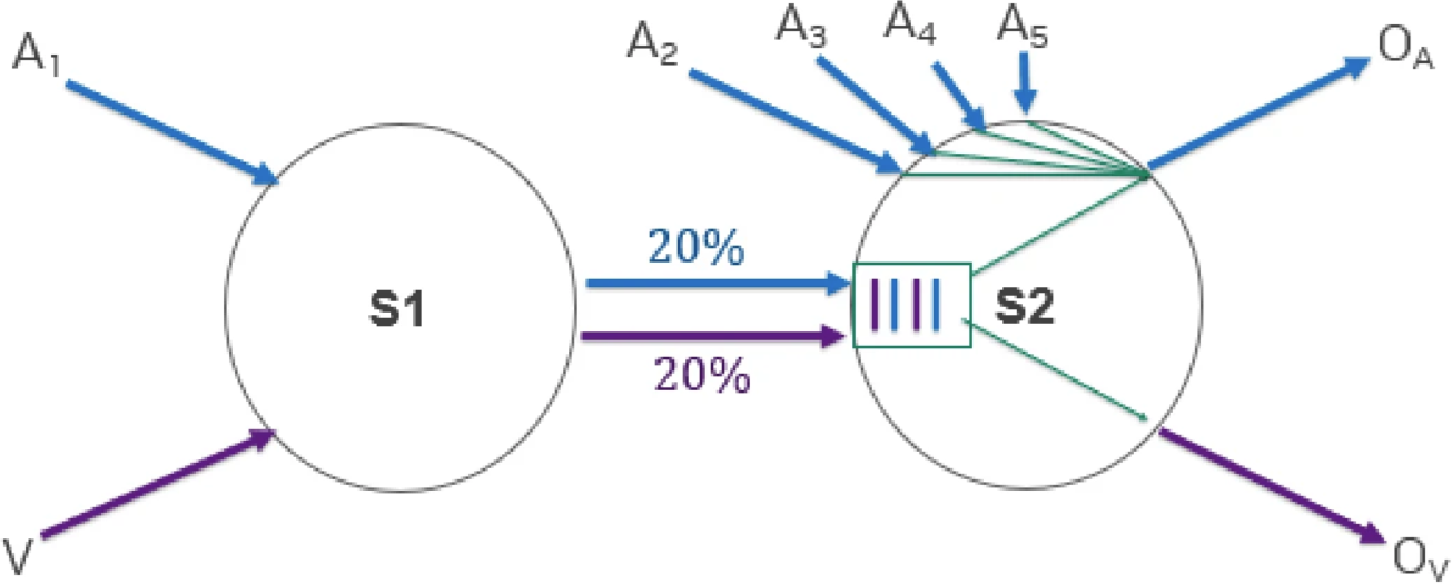
Consider a scenario with two switches, S1 and S2:
-
The Shared Link:
S1is forwarding two different traffic flows toS2: a blue flow () destined for egress port
, and a purple flow (
) destined for egress port
. They share the physical link between
S1andS2. -
The Congestion Point: At switch
S2, the blue flow () must compete with several other incoming blue flows (
,
,
,
) that are all trying to exit out of the same port (
). This aggregation overwhelms
, causing blue packets to back up into
S2's shared ingress queue. -
The HOL Blocking Effect: Because that shared queue fills up with congested blue packets, the purple packets (
) get stuck waiting behind them; even though their destination port (
) is completely uncongested and ready to transmit.
A highly responsive CC algorithm like ZTR-RTT prevents HOL blocking by detecting the delay on the blue flow and throttling it before it can fill the shared queue, allowing the purple flow to pass through uninterrupted.
ZTR-RTT Congestion Indications
To determine the health of the network path and avoid the buffering scenarios described above, the algorithm monitors two primary congestion indicators:
-
RTT (Round Trip Time): Real-time measurement of the delay between sending a packet and receiving its acknowledgment.
-
CNP (Congestion Notification Packet): Explicit notifications sent by the network or receiver when congestion is encountered.
Rate Update Scheme
The algorithm continuously evaluates the current congestion state by comparing the measured RTT against the expected delay based on the current transmission rate.
-
Congestion Evaluation: The congestion state is determined mathematically by comparing the measured RTT to
.
-
Adjustment Method: Based on this evaluation, the algorithm employs an Additive Increase (gradually adding to the rate when the network is clear) and a Multiplicative Decrease (cutting the rate by a percentage when congestion is detected) approach to maintain an optimal flow.
Algorithmic Windowing & Fast Reaction
-
Algorithmic Windowing: The algorithm mimics traditional window-based CC behavior (similar to standard TCP) by adjusting the transmission rate dynamically whenever the measured RTT changes.
-
Fast Reaction on First Congestion: The algorithm is designed to implement an immediate, fast rate reaction upon the very first indication of network congestion, preventing severe packet drops and maintaining a stable fabric.
RTT Measurement Flow
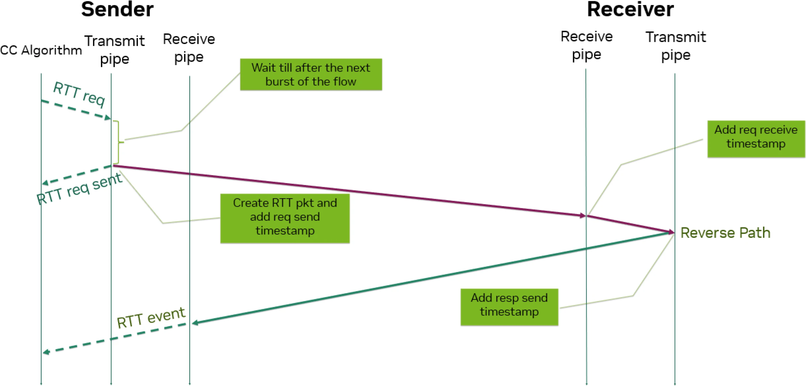
To accurately calculate the RTT without introducing excessive processing overhead, the Sender (Reaction Point) and Receiver (Notification Point) execute a highly synchronized, hardware-assisted timestamping sequence:
-
Initiation (Sender): The CC algorithm initiates an
RTT req(Request). -
Sender Transmit Pipe: The transmit pipe waits until after the next burst of the flow. It then creates the RTT packet and stamps it with a req send timestamp before transmitting it across the network (
RTT req sent). -
Receiver Receive Pipe: The packet arrives at the Receiver, where the receive pipe immediately adds a req receive timestamp.
-
Receiver Transmit Pipe (Reverse Path): As the acknowledgment packet is routed back to the sender, the transmit pipe adds a resp send timestamp.
-
Completion (Sender): The packet arrives back at the Sender's receive pipe, which extracts all the timestamp data and triggers an RTT event back to the CC algorithm to calculate the final delay and update the rate accordingly.
Last updated: