This guide provides an overview and configuration instructions for the DOCA Programmable Congestion Control (PCC) API.
Introduction
The quality status of DOCA libraries is listed here.
The DOCA PCC library offers a high-level programming interface that enables users to implement customized congestion control (CC) algorithms. By leveraging the NVIDIA® BlueField®-3 platform hardware acceleration, it facilitates efficient network congestion management while abstracting away hardware complexities.
With the DOCA PCC API, users can:
-
Configure probe packets for sending and receiving
-
Retrieve CC events or packets and access their fields
-
Set flow rate limits to regulate network traffic
-
Maintain per-flow contexts for individualized management
-
Initiate and configure CC algorithms tailored to application needs
-
Process incoming request packets and generate appropriate response packets
This streamlined API allows developers to focus on designing and implementing congestion control logic without worrying about low-level hardware operations.
Prerequisites
DOCA PCC-based applications can run on either the host machine or the NVIDIA BlueField-3 Platform (or later) target.
Currently, DOCA PCC is supported only for the ETHERNET link type.
Enabling DOCA PCC
To enable DOCA PCC RP:
-
On the host/VM, run:
mlxconfig -d <mlx_device> -y s USER_PROGRAMMABLE_CC=1
-
Perform a graceful shutdown and then power cycle the host.
To enable DOCA PCC NP:
-
On the host/VM, run:
mlxconfig -d <mlx_device> -y s PCC_INT_EN=0
-
Perform a graceful shutdown and then power cycle the host.
Configuration Notes
-
Setting
PCC_INT_EN=1blocks the creation of DOCA PCC NP context and enables the legacy NP solution. It also only supports DOCA PCC RP context for setting Congestion Control Message After Drop (CCMAD) probe packet format. -
For IFA2.0 support, enable both DOCA PCC RP and DOCA PCC NP on all cluster nodes.
-
The DOCA PCC NP process requires root access.
-
For BlueField-3 devices in DPU mode, executing the DOCA PCC NP process on an x86 host is not supported.
-
When running from an x86 host in NIC mode, privileged permissions are required. Check the privilege level using
mlxprivhost -d <mlx_device> q. -
To enable the injection of response timestamp information into probe response payloads, you must set
FLEX_PARSER_PROFILE_ENABLE=10in the device's non-volatile (NV) configuration.mlxconfig -d <mlx_device> -y s FLEX_PARSER_PROFILE_ENABLE=10
DPACC Tool
The DPACC tool compiles and links user algorithms and device code with the DOCA PCC device library to create loadable applications. DPACC is included in the DOCA SDK installation package. For more information, refer to DOCA DPACC Compiler documentation.
Changes From Previous Releases
Changes in 3.3.0
Added
-
Support for injecting response timestamp in DOCA PCC NP.
Dependencies
The library requires firmware version 32.38.1000 and higher.
Architecture
DOCA PCC comprises three main components which are part of the DOCA SDK installation package.
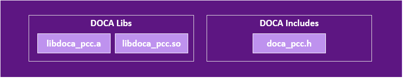
Host Library
The host library offers a unified interface for managing the DOCA PCC context configuration.
As part of the control path, the host library integrates passively within the application, orchestrating congestion control activities without directly handling data transmission.
Host/device library and header files:
Device Libraries
The DOCA PCC context assumes one of two roles:
-
Reaction point (RP): Monitors network conditions actively, dynamically adjusting data transmission rates to alleviate congestion promptly. RP context is global per NIC.
Device library and header files:
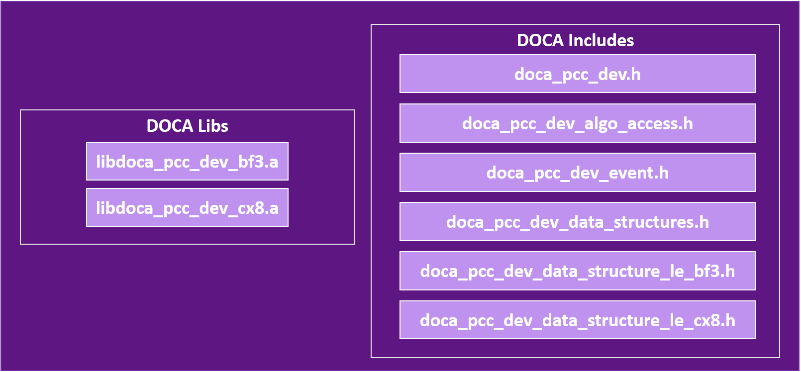
-
Notification point (NP): Passively receives congestion notifications from external sources, processing them intelligently to facilitate informed decisions within the application. NP context is global per e-switch owner.
Device library and header files:

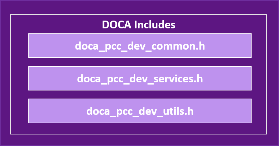
Both RP and NP device libraries share common headers:
Currently, the device library and the user algorithm are implemented and managed over the BlueField's data-path accelerator (DPA) subsystem.
For more info on DPA, refer to DPA Subsystem.
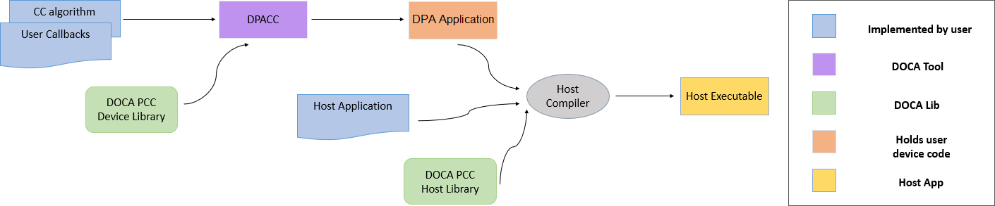
Development Flow
DOCA enables developers to program the congestion control algorithm into the system using the DOCA PCC library.
The following are the required steps to start programming:
-
Implement CC algorithms and probe packet handling using the API provided by the device header files.
-
Implement the user callbacks defined by the library for DataPath:For RP: doca_pcc_dev_user_init(), doca_pcc_dev_user_set_algo_params(), doca_pcc_dev_user_algo().For NP: doca_pcc_dev_np_user_packet_handler()
-
Use DPACC to build a DPA application (i.e., a host library which contains an embedded device executable). Input for DPACC are the files containing the implementation of the previous steps.
-
Build host executable using a host compiler. Inputs for the host compiler are the DPA application generated in the previous step and the user application host source files.
-
In the host executable, create and start a DOCA PCC context which is set with the DPA application containing the device code.
For a more descriptive example, refer to NVIDIA DOCA PCC Application Guide.
The PCC program must be loaded before the QP is created. If the QP is created first, it will not be able to access the PCC program context. This dependency is strict; reversing the order causes PCC features to fail or result in undefined library behavior.
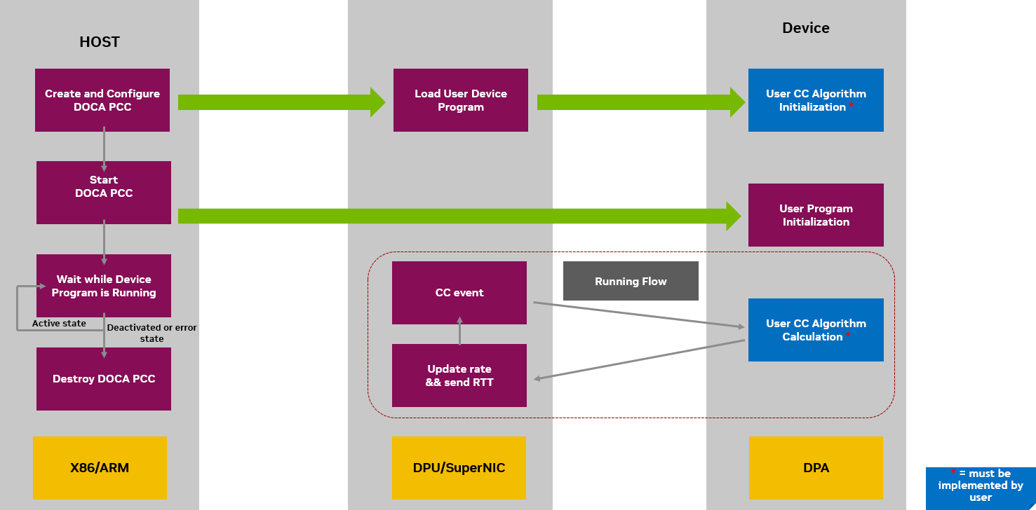
System Design
DOCA PCC flow for implementing an RP program:
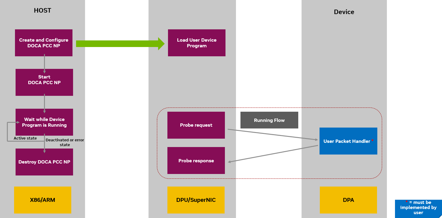
DOCA PCC flow for implementing an NP program:
API
For the library API reference, refer to PCC API documentation in the API References.
The following sections provide additional details about the library API.
Host API
The host library API consists of calls to set the PCC context attributes and observe availability of the process.
Selecting and Opening DOCA Device
To perform PCC operations, a device must be selected. To select a device, users may iterate over all DOCA devices using doca_devinfo_list_create() and check whether the device supports the desired PCC role either via doca_devinfo_get_is_pcc_supported() for RP, or doca_pcc_np_cap_is_supported() for NP.
Setting Up and Starting DOCA PCC Context
After selecting a DOCA device, a PCC context can be created.
As described in the Architecture section, The DOCA PCC library provides APIs to leverage Reaction Points (RP) and Notification Points (NP) to implement programmable congestion control strategies.
Call doca_pcc_create() to create a DOCA PCC RP context, and doca_pcc_np_create() to create a DOCA PCC NP context.
Afterwards, the following attributes must be set for the PCC context:
-
Context app – the name of the DPA application compiled using DPACC, consisting of the device algorithm and code. This is set using the call
doca_pcc_set_app(). -
Context threads – the affinity of DPA threads to be used to handle CC events. This is set using the call
doca_pcc_set_thread_affinity(). The number of threads to be used must be constrained between the minimum and maximum number of threads allowed to run the PCC process (seedoca_pcc_get_min_num_threads()anddoca_pcc_get_max_num_threads()). The availability and usage of the threads for PCC is dependent on the complexity of the CC algorithm, link rate, and other potential DPA users.Users can manage DPA threads in the system using EU pre-configuration with the
dpaeumgmttool. For more information, refer to Single Point of Resource Distribution.
After setting up the context attributes, the context can be started using doca_pcc_start(). Starting the context initiates the CC algorithm supplied by the user.
Configuring Probe Packets
The DOCA PCC library provides APIs to configure the probe packet settings to tailor congestion control behaviors according to specific network conditions.
The probe packet serves to probe the network for congestion and gather essential feedback for congestion control algorithms.
The DOCA PCC Library supports the following probe packet types:
-
CCMAD – Provides information about the network's round-trip time so the algorithm can detect and adapt to congestion proactively
-
IFA1 – In-band Flow Analyzer 1 packets provide in-band congestion feedback for proactive congestion control
-
IFA2 – In-band Flow Analyzer 2 packets offer an alternative method for in-band congestion feedback, optimized for specific network environments
Configuring Dedicated Fields for Different Probe Types
The DOCA PCC library provides APIs to configure specific fields in different supported probe packet types.
-
IFA1 – support to configure probe marker
-
IFA2 – support to configure GNS and hop limit
Configuring Remote NP Handler
To enable Reaction Point contexts to interact with remote Notification Point contexts, the DOCA PCC library provides an API to set the expected remote handler type.
When the DOCA PCC RP process expects CCMAD probe packet responses from a DOCA PCC NP process, it should set it as so using the API doca_pcc_rp_set_ccmad_remote_sw_handler(). If not set, the DOCA PCC RP process expects that no remote DOCA PCC NP process is activated, and that responses are handled by the remote node's hardware. Note that if using probe types other than CCMAD, probe packet responses are always expected to be generated from a remote DOCA Notification Point process.
RTC Timestamps for PCC
To use the real-time clock (RTC) as the timetable for both DOCA PCC RP (requesting party) and DOCA PCC NP (notifying party), the clocks on both endpoints must be synchronized (e.g., using PTP). Synchronization details are outside the scope of this documentation.
By default, RTT probe packet timestamps are taken from the device's free-running clock. The steps below describe how to configure and use RTC-based timestamps.
Configuring RTC in DOCA PCC RP
-
Enable RTC on the device.
mlxconfig -d <mlx_device> -y s REAL_TIME_CLOCK_ENABLE=1
-
Configure RTT timestamp format to use RTC (value 2).
mlxconfig -d <mlx_device> -y s ROCE_CC_RTT_TIMESTAMP_FORMAT=2
This NV config setting requires MFT version 4.34 or newer.
-
retrieve the RTT request timestamp (T1) using the API
doca_pcc_dev_get_rtt_req_recv_timestamp();. This function is compatible with both RTC and free-running clock sources.
Configure RTC in DOCA PCC NP
-
Enable RTC on the device.
mlxconfig -d <mlx_device> -y s REAL_TIME_CLOCK_ENABLE=1
-
In the host-side code, configure the NP to use the RTC timestamp source using the following APIs:doca_pcc_np_cap_is_ts_source_supported(): Verifies if the device supports the specific timestamp source (defined in doca_pcc_np_ts_source_t).doca_pcc_np_set_ts_source(): Sets the NP to use the specified timestamp source.Configuring the timestamp source in the DOCA PCC NP requires flexio-sdk version 25.10.xxxx or newer.
-
In the device code, retrieve the RTT request receive timestamp (T2) using
doca_pcc_np_dev_get_t2_ns().This API returns a 30-bit value for nanoseconds in little-endian format. It is compatible with both RTC and free-running clock sources.
DOCA PCC Notification Point: Response Timestamp
Response timestamp allows the DOCA PCC Notification Point (NP) to inject timestamp information directly into probe response payloads. This facilitates precise timing measurements in congestion control scenarios by capturing a timestamp at the moment the probe response is transmitted from the port.
When enabled, the timestamp is automatically inserted into the least-significant bits of the last DWORD of the Congestion Control (CC) probe response payload. This allows the Reaction Point (RP) to calculate accurate round-trip times (RTT) and make informed congestion control decisions.
Configuring Response Timestamp
To enable the injection of response timestamps, you must set the Flex Parser profile to 10 in the device's non-volatile (NV) configuration.
mlxconfig -d <mlx_device> -y s FLEX_PARSER_PROFILE_ENABLE=10
Response Timestamp API Reference
-
doca_pcc_np_cap_is_resp_ts_supported()– Queries whether the device supports injecting response timestamps into probe response payloads for Notification Point operations. -
doca_pcc_np_set_resp_ts_size()– Configures the number of bits (ts_size) used for the timestamp within the last DWORD of the payload.-
0: Response timestamp injection is disabled (Default). -
1-32: The timestamp is injected into the least-significantts_sizebits of the last DWORD.Larger sizes provide higher precision but consume more payload space. Use
doca_pcc_np_set_resp_ts_resolution()to adjust the time scale if the value range is insufficient.
-
-
doca_pcc_np_set_resp_ts_resolution()– Sets the granularity of the timestamp by configuring a right-bit shift applied to the raw timestamp before injection. This allows trading precision for an extended time range.-
0: No shift applied (maximum precision) (Default). -
N: The raw timestamp is right-shifted byNbits (effectively dividing by 2N).
-
-
doca_pcc_np_set_ts_source()– Selects the hardware clock source. This setting applies globally to NP operations, affecting both the response timestamp injection and thedoca_pcc_np_dev_get_t2_ns()device API.
The DOCA_PCC_NP_TS_SOURCE_DEFAULT enum value is deprecated in this release and will be removed in an upcoming version. Applications must explicitly select a valid timestamp source (e.g., FREE_RUNNING or REAL_TIME).
typedef enum {
    DOCA_PCC_NP_TS_SOURCE_FREE_RUNNING = 0,                   /**< Free running timestamp. */
    DOCA_PCC_NP_TS_SOURCE_DEFAULT DOCA_DEPRECATED_ENUM = 0x1, /**< @deprecated Deprecated in this release; will be removed in an upcoming release. */
    DOCA_PCC_NP_TS_SOURCE_REAL_TIME = 0x2,                    /**< Real time timestamp. */
} doca_pcc_np_ts_source_t;
Debuggability
The DOCA PCC library provides a comprehensive set of debugging APIs. These tools allow you to diagnose issues, pinpoint bottlenecks, and access real-time information from your running device-side application.
PCC Tracer
The library’s tracer is optimized for high-frequency use. It allows you to observe device algorithm behavior and diagnose issues with negligible impact on application performance.
PCC tracing is enabled by default when doca_pcc_start() is called. By default, trace output is routed to stdout.
Tracer API reference:
|
Category |
API Function |
Description |
|---|---|---|
|
State control |
|
Disables runtime trace printing. |
|
|
Re-enables tracing dynamically without restarting the PCC context. |
|
|
Destination config |
|
Routes trace output to a user-supplied buffer. |
|
|
Routes trace output to a specified file. |
|
|
|
Queries the currently configured destination buffer. |
|
|
|
Queries the currently configured destination file. Returns |
|
|
Formatting and handling |
|
Sets the specific trace message string used for device printing. |
|
|
Registers a custom callback function for programmatic handling. The callback receives a user context pointer and an array of arriving device trace reports. |
PCC Logger
The logger handles explicit messages generated by the device API doca_pcc_dev_printf().
Unlike the tracer, device-side prints incur measurable performance overhead. Use them sparingly for short-term debugging or targeted diagnostics. For ongoing observability, use the PCC Tracer.
Logger API reference:
|
Category |
API Function |
Description |
|---|---|---|
|
Destination config |
|
Configures the size of the buffer used to accumulate device-side print data ( Incurs measurable performance overhead; use sparingly. |
|
|
Routes log output to a specified file. |
|
|
|
Queries the currently configured destination file. Returns |
Device Coredump File
The coredump utility captures crucial device crash data when an unrecoverable error occurs on the device side of the application. The resulting file includes a memory snapshot at the exact time of the crash, detailing the program's state, variable values, and the call stack.
Coredump API reference:
-
doca_pcc_set_dev_coredump_file()– Configures the host-side file path to capture device crash data (memory snapshot, call stack, variables) when an unrecoverable error occurs on the device side.
Device Mailbox
The DOCA PCC library provides a set of APIs for sending and receiving messages through a mailbox. This service allows communication between the host and device:
-
doca_pcc_set_mailbox()– API to set the mailbox attributes for the process. -
doca_pcc_mailbox_get_request_buffer()anddoca_pcc_mailbox_get_response_buffer()– API to get the buffers with which the communication will be handled. User can set the request he wants to send to the device, and get a response back. -
doca_pcc_mailbox_send()– API to send the mailbox request to the device. This is a blocking call which invokes a callback on the devicedoca_pcc_dev_user_mailbox_handle()which user can handle.
High Availability
The DOCA PCC library supports High Availability (HA) to ensure continuous operation and recovery if the running PCC process malfunctions. You can achieve this by running multiple PCC processes in parallel.
Process Lifecycle and Failover
-
Call
doca_pcc_start()to register multiple PCC processes in parallel with the NIC firmware. -
The firmware designates the first process to register as the ACTIVE process (running on the DPA and handling Congestion Control events). All subsequent processes are automatically placed in STANDBY mode.
-
Continuously observe the status of your processes using
doca_pcc_get_process_state(). If a state change occurs, thedoca_pcc_wait()function will return. -
If the currently ACTIVE process encounters an error or stops processing events, the firmware automatically promotes one of the STANDBY processes to become the new ACTIVE process.
-
The defunct (failed) process must explicitly call
doca_pcc_destroy()to safely free its allocated resources.Configuration state is not replicated across processes. When a failover occurs, the replacement process does not automatically receive new algorithm configurations, and any user-applied PPCC commands are lost and must be re-applied manually.
Process States (doca_pcc_process_state_t)
The following table details the possible states of a PCC process at any given time:
|
State Enum |
Value |
Description |
Action Required |
|---|---|---|---|
|
|
|
The process is actively handling CC events. |
None (Only one process is active at a time). |
|
|
|
The process is waiting in standby mode. |
None (Another process is currently ACTIVE). |
|
|
|
The process was deactivated by the NIC Firmware. |
Must call |
|
|
|
The process has encountered an error. |
Must call |
PCC Resources
The PCC Resources API provides a mechanism to parse and query pre-defined PCC resource configurations. This enables applications to discover and utilize the Execution Units (EUs) allocated to them in the Single Point of Resource Distribution (SPRD) file.
The SPRD file is a YAML-formatted configuration file that defines PCC application resources. It specifies:
-
Application names (keys).
-
The number of allocated EUs per application.
-
The specific EU IDs assigned to each application.
For file syntax and examples, refer to the Single Point of Resource Distribution documentation.
Key functions:
|
Function |
Description |
|---|---|
|
|
Creates a PCC resources object by parsing an SPRD buffer and extracting the configuration for a specific application |
|
|
Releases all resources associated with a PCC resources object |
|
|
Retrieves the number of EUs allocated to the application in the PCC resources object |
|
|
Retrieves the array of EU IDs allocated to the application |
Device API
The device library API provides the necessary calls to set up and manage your congestion control (CC) algorithms so they can handle CC events arriving directly on the hardware.
Counter groups
Counter groups are port-level arrays of 32-bit counters, each owned by either an algorithm slot or a histogram. The library natively supports between 1 and 15 groups per port (defaulting to 2).
|
Function |
Description |
|---|---|
|
|
Declares the number of counter groups per port. (Note: Must be called within |
|
|
Binds a specific counter group to an algorithm slot. |
|
|
Initializes a counter's metadata, including its maximum value, permissions, and description. |
|
|
Retrieves a pointer to the counter array for a specific algorithm slot. |
|
|
Retrieves the total number of counters assigned to an algorithm slot. |
Counter Sampling
These APIs allow you to sample NIC byte counters to monitor the amount of data transmitted and received through the NIC.
It is highly recommended to configure the counters inside the doca_pcc_dev_user_port_info_changed() callback, as this indicates the correct port state to sample from.
|
API Function |
Description |
|---|---|
|
|
Prepares the list of counters you want to read. |
|
|
Samples and retrieves the new counter values. |
Algorithm Access
The Reaction Point (RP) device library supports running multiple PCC algorithms, useful for fast A/B testing and comparative runs. You can utilize the default library algorithm alongside your own custom algorithms.
|
Category |
API Function |
Description |
|---|---|---|
|
Core |
|
Loads the default CC algorithm (can be used fully or partially). |
|
|
Assigns a specific algorithm to run on a designated device port (slot). |
|
|
Initialization |
|
Initiates the algorithm's parameters. |
|
|
Initiates the algorithm's counters. |
|
|
|
Initiates the algorithm's metadata base. |
Dynamic Memory on DPA
By default, the DOCA PCC library allocates DPA global memory at the maximum possible size for all resources—assigning all 8 algorithm slots on every port, each equipped with the maximum number of parameters and counters.
In memory-constrained DPA environments, this default behavior is wasteful. To optimize resource usage, developers can use the doca_pcc_dev_user_declare_memory() callback to declare exactly what memory is required. The library utilizes these declarations to compute a right-sized memory allocation.
This callback is executed exactly once during process startup, strictly before doca_pcc_dev_user_init().
Memory Declaration APIs
The functions below must be called exclusively inside doca_pcc_dev_user_declare_memory().
|
Function |
Declaration Purpose |
Default Behavior (If Omitted) |
|---|---|---|
|
|
Maps an algorithm index to a specific port slot. Slots left unassigned ( |
All slots are assigned on all ports (maximum memory consumption). |
|
|
Sets the exact number of parameters and counters required for an algorithm. |
44 parameters and 63 counters per algorithm. |
|
|
Sets the number of counter groups per port (Range: 1–15). |
2 counter groups. |
|
|
Sets the number of histograms per port (Range: 0–15). |
0 (Histograms disabled). |
|
|
Sets the per-thread counter sets, effectively multiplying the counter pool. |
1 shared set per group. |
Algorithm Selection
Algorithms are enabled or disabled on specific "algo slots" using either doca_pcc_dev_init_algo_slot() or the mlxreg command (cmd_type 1 and 2).
The algorithm that is ultimately selected for traffic depends on the negotiation between the two connection endpoints:
-
Successful negotiation (with ECE): Occurs if both endpoints support Enhanced Congestion Control (ECE). Each Queue Pair (QP) specifies its CC algo slot via ECE. If multiple algorithms are enabled, the one with the lowest shared slot index is selected.
-
No negotiation (without ECE): If ECE is not supported or not enabled, no negotiation occurs. The system defaults to the default algorithm slot.
-
For example, When testing with
ib_write_bw, algorithm negotiation only executes if you pass the--rdma_cmparameter on both the client and server (which enables ECE).
-
Events
The RP device library provides optimized helper functions to access CC events. These supply the runtime data needed to analyze and inspect hardware events and build out your CC algorithm logic.
Utilities
A set of optimized utility macros (such as fixed-point math operations, memory space fences, etc.) are included to streamline the programming of your CC algorithm on the device.
User Callbacks
The library relies on specific user-implemented callbacks to initiate the CC algorithm and handle packet I/O.
These callbacks must be implemented in your code and compiled by DPACC to be properly provided to the DOCA PCC context in your DPA application.
Reaction point (RP) callbacks:
|
Callback Function |
Trigger/Purpose |
|---|---|
|
|
Called on PCC process load. Use this to initialize the data for all user algorithms. |
|
|
The primary entry point to your custom user algorithm handling code. |
|
|
Called whenever an algorithm parameter change is triggered externally. |
Notification point (NP) callbacks:
|
Callback Function |
Trigger/Purpose |
|---|---|
|
|
Called immediately upon the arrival of probe packets. |
Debuggability
PCC Tracer
The device-side tracer is the preferred method for ongoing observability, designed to minimize performance impact compared to standard prints.
The message format must be pre-configured on the host using doca_pcc_set_trace_message().
|
API Function |
Description |
|---|---|
|
|
Emits formatted trace records containing up to five arguments.
|
|
|
Forces a partially filled trace buffer to the host. Avoid frequent use; typically reserved for the end of a run. |
PCC Logger
Intended strictly for short-term debugging convenience.
|
API Function |
Description |
|---|---|
|
|
Prints device-side messages directly to the host Frequent use degrades performance, and dropped messages may occur due to limited host buffering. |
Histograms
The DOCA PCC library includes a comprehensive histogram API, allowing user algorithms to collect and expose distribution data at runtime (e.g., RTT latency distributions, rate distributions, or application-specific metrics). Histograms are a device-side feature managed through the Reaction Point (RP) device API.
Histogram characteristics:
-
Each histogram owns a dedicated counter group for storing bin values.
-
Each histogram is identified by a unique ID.
-
Histograms support configurable binning modes and dynamic edge values.
-
Histograms can be queried and reconfigured remotely via PPCC commands without requiring application recompilation.
Histogram Concepts
A histogram partitions a range of values into bins defined by an array of edges. When the user algorithm records a value via doca_pcc_dev_histogram_update(), the library identifies the matching bin and increments the corresponding counter.
Because each histogram requires its own dedicated counter group, the total number of histograms per port is strictly bounded by the number of available counter groups (up to 15).
Binning Modes
The histogram mode dictates how the edge values are interpreted. This is specified at initialization using the doca_pcc_dev_histogram_mode_t enum:
|
Mode |
Enum Value |
Description |
|---|---|---|
|
Linear |
|
Creates equally spaced bins. The edges array defines uniform intervals. |
|
Exponential |
|
Creates exponentially growing bin widths. This is ideal for distributions spanning several orders of magnitude (e.g., latency). |
|
Free |
|
Allows arbitrary, user-defined edge values, providing full control over bin boundaries. |
Hardware Limits
|
Constant |
Value |
Description |
|---|---|---|
|
|
32 |
The maximum number of bins permitted per histogram. |
|
|
|
The maximum histograms per port (which equals the max counter groups). |
|
|
0 |
The default number of histograms (disabled by default unless explicitly declared). |
Histogram Lifecycle
-
Declare: Optionally call
doca_pcc_dev_declare_num_of_histograms()to allocate the required number of histograms. -
Initialize: Within the
doca_pcc_dev_user_init()callback, calldoca_pcc_dev_histogram_init()for each histogram. This assigns the histogram to a counter group and sets its edges, mode, and description. -
Register: Call
doca_pcc_dev_algo_register_hist_ids()to bind histogram IDs to an algorithm slot, enabling remote discovery via PPCC. -
Update: Inside the CC event handler (
doca_pcc_dev_user_algo()), calldoca_pcc_dev_histogram_update()to record observed values and increment the appropriate bin. -
Query: Read histogram configuration and bin data remotely via PPCC commands (e.g.,
0x13for descriptions,0x14for configurations/edges, and0xC/0xDfor bin values). -
Reconfigure: Enable, disable, or reconfigure histograms remotely via PPCC command
0x15, or programmatically usingdoca_pcc_dev_histogram_disable()anddoca_pcc_dev_histogram_enable(). -
Clear: Call
doca_pcc_dev_histogram_clear()to reset all bin counters to zero.The histogram must be disabled prior to clearing.
Device API Reference
All histogram functions are declared in doca_pcc_dev_algo_access.h, while the histogram handle type and mode enum are defined in doca_pcc_dev_types.h.
|
Category |
API Function |
Description |
|---|---|---|
|
Initialization |
|
Sets the number of histograms per port. If not implemented, the default (0) is used. |
|
|
Initializes a histogram instance on a given counter group and histogram ID. |
|
|
|
Registers histogram IDs for an algorithm slot, enabling remote discovery via PPCC. |
|
|
Data Path |
|
Records a value. The library automatically finds the matching bin and increments its counter. |
|
Control |
|
Enables a previously disabled histogram (re-enables without changing its parameters). |
|
|
Disables a histogram. This stops the bins from updating, but existing bin values are preserved. |
|
|
|
Clears all bin counters to zero. The histogram must be disabled before clearing. |
|
|
Query |
|
Returns a pointer to the histogram's description string. |
Usage Example
The following example demonstrates how to initialize two histograms (for RTT and rate distributions) and update them directly from the CC event handler:
#include "doca_pcc_dev_algo_access.h"

#define NUM_FUNCTIONAL_COUNTER_GROUPS 1
#define NUM_HISTOGRAMS 2
#define HIST_ID_RTT    0
#define HIST_ID_RATE   1

static doca_pcc_dev_histogram_t rtt_hist;
static doca_pcc_dev_histogram_t rate_hist;

/* Declare the number of histograms needed in memory declaration callback */
void doca_pcc_dev_user_declare_memory(void)
{
    doca_pcc_dev_declare_num_counter_groups(NUM_FUNCTIONAL_COUNTER_GROUPS + NUM_HISTOGRAMS);
    doca_pcc_dev_declare_num_of_histograms(NUM_HISTOGRAMS);
}

void doca_pcc_dev_user_init(uint32_t port_num, uint32_t algo_slot, doca_pcc_dev_algo_meta_t *algo_meta)
{
    /* 10 linearly-spaced bins for RTT (edges in nanoseconds) */
    uint32_t rtt_edges[] = {0, 100, 200, 300, 400, 500, 600, 700, 800, 900, 1000};

    doca_pcc_dev_histogram_init(
        port_num, DOCA_PCC_DEV_TARGET_APP_RP,
        /* counter_group_id */ 1,
        HIST_ID_RTT, rtt_edges, 10,
        DOCA_PCC_DEV_HISTOGRAM_MODE_LINEAR,
        "RTT distribution (ns)", &rtt_hist);

    /* 8 exponentially-growing bins for rate */
    uint32_t rate_edges[] = {0, 1, 2, 4, 8, 16, 32, 64, 128};

    doca_pcc_dev_histogram_init(
        port_num, DOCA_PCC_DEV_TARGET_APP_RP,
        /* counter_group_id */ 2,
        HIST_ID_RATE, rate_edges, 8,
        DOCA_PCC_DEV_HISTOGRAM_MODE_EXPONENTIAL,
        "Rate distribution (Gbps)", &rate_hist);

    /* Register histogram IDs with the algorithm slot */
    uint32_t hist_ids[] = {HIST_ID_RTT, HIST_ID_RATE};
    uint32_t algo_idx = doca_pcc_dev_get_algo_index(port_num, algo_slot);
    doca_pcc_dev_algo_register_hist_ids(algo_idx, hist_ids, NUM_HISTOGRAMS);
}

/* In the CC event handler */
void doca_pcc_dev_user_algo(/* ... event parameters ... */)
{
    uint32_t rtt = /* extract RTT from event */;
    uint32_t rate = /* extract rate from event */;

    doca_pcc_dev_histogram_update(rtt_hist, rtt);
    doca_pcc_dev_histogram_update(rate_hist, rate);
    /* ... rest of algorithm logic ... */
}
Remote Management via PPCC
Once initialized and registered, histograms can be discovered, queried, and reconfigured dynamically using the Port Programmable Congestion Control (PPCC) register.
|
Command (cmd_type) |
Method |
Description & Key Fields |
|---|---|---|
|
|
Get |
Get histogram IDs for algorithm slot.
|
|
|
Get |
Get histogram description.
|
|
|
Get |
Get histogram configuration and data.
|
|
|
Set |
Set histogram parameters.
|
For commands 0x13, 0x14, and 0x15, the algo_slot field (offset 0x04, bits 3:0) strictly carries the Histogram ID, not the algorithm slot number.
Histogram bin counter values are stored in the histogram’s assigned counter group and can be read using standard counter commands (0xC, 0xD) with cfg_counter_group_en=1 and the appropriate counter_group_id.
For detailed PPCC register field descriptions, command examples, and mlxreg usage, refer to section "Port Programmable Congestion Control Register" in the DOCA PCC Application Guide.
Last updated: