Remote Direct Memory Access (RDMA) enables direct memory-to-memory data transfers between servers, bypassing CPU involvement. RoCE (RDMA over Converged Ethernet) extends RDMA functionality to lossless Ethernet networks, delivering high-throughput, ultra-low latency communication.
With advancements in reliable Ethernet technologies, the NVIDIA® ConnectX® Ethernet adapter family supports RDMA transport over 10GigE and 40GigE networks. By offloading RDMA services to hardware, these adapters significantly reduce CPU load and latency—making them ideal for performance-critical applications like financial systems, databases, storage, and content delivery networks.
Key Considerations for RoCE
When deploying RDMA applications over Ethernet, consider the following:
-
No Subnet Manager (SM) – Unlike InfiniBand, RoCE does not require an SM. However, certain operations (e.g., multicast group joins) must be handled differently, even though the API remains unchanged.
-
No LID (Local ID) – As LID is specific to InfiniBand, it is not set for RoCE ports and appears as zero in queries.
-
No APM (Alternate Path Migration) – RoCE does not support APM, as it relies on InfiniBand-specific mechanisms.
-
Manual Path Record Setup – Since path querying is not possible without an SM, users must manually populate the path record structure before establishing a connection. Using RDMA-CM is strongly recommended, as it automates path record handling.
-
Priority Mapping via VLAN Tags – VLAN-tagged Ethernet frames use a 3-bit priority field derived from the 3 least significant bits of the InfiniBand Service Level (SL) field.
-
RoCE Traffic Counters – RoCE traffic is offloaded by hardware and is not visible in standard Ethernet interface counters. Instead, RoCE traffic statistics can be found at:
/sys/class/infiniband/<device>/ports/<port number>/counters/
RoCE Modes
RoCE encapsulates IB transport in one of the following Ethernet packets:
-
RoCEv1 - uses a dedicated ethertype (
0x8915) -
RoCEv2 - encapsulates RDMA in UDP/IP packets, using UDP port
4791
RoCEv1 and RoCEv2 Protocol Stack
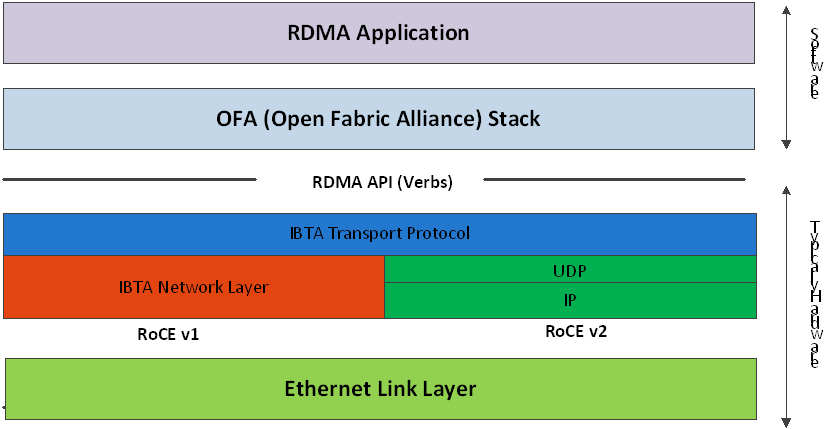
RoCEv1
RoCEv1 uses a dedicated Ethernet EtherType (0x8915). It may include or omit VLAN tags and adheres to the standard Ethernet MTU. It is a Layer 2 protocol and is limited to communication within the same Ethernet broadcast domain.
RoCEv2
RoCEv2 extends RDMA to Layer 3 networks by encapsulating RDMA traffic in UDP/IP packets. This allows traffic to traverse IP routers and use standard IP routing. Key features include:
-
IP Header – Enables routing across IP networks.
-
UDP Header – Used for stateless encapsulation; destination port
4791. -
Source Port Field – Can serve as an opaque flow ID to assist with ECMP (Equal-Cost Multi-Path) routing.
Since the packet format change occurs at the wire level and does not affect the RDMA API, applications can operate seamlessly over RoCEv1 or RoCEv2 without modification.
Both RoCEv1 and RoCEv2 are supported by default. The driver associates GID indexes with both modes, creating one entry per version.
For deployment examples, see the Recommended Network Configuration Examples For RoCE Deployment community post.
GID Table Population
GID (Global Identifier) table entries are automatically created when an IP address is configured on an Ethernet device associated with a RoCE port. Each GID entry includes:
-
GID value
-
GID type (e.g., RoCEv1, RoCEv2)
-
Associated network device
By default, each RoCE-capable port has two GID entries with the same value but different types (RoCEv1 and RoCEv2). GID format can be:
-
IPv4 GID – An IPv4-mapped IPv6 address
-
IPv6 GID – A native IPv6 address
The Layer 3 header depends on the GID type:
-
For RoCEv2 – IPv4 or IPv6
-
For RoCEv1 – Uses IPv4 GIDs as-is, with GRH if required
Accessing GID Table via Sysfs
The GID (Global Identifier) table is exposed to userspace via sysfs and provides details for each GID entry associated with a RoCE-capable port:
-
GID value:
/sys/class/infiniband/{device}/ports/{port}/gids/{index} -
GID type (e.g., RoCEv1 or RoCEv2):
/sys/class/infiniband/{device}/ports/{port}/gid_attrs/types/{index} -
Associated network device:
/sys/class/infiniband/{device}/ports/{port}/gid_attrs/ndevs/{index}
Each file in this directory represents a GID index and contains the corresponding GID value.
Setting the RoCE Mode for a QP
For devices supporting both RoCEv1 and RoCEv2, selecting the desired mode depends on the Queue Pair (QP) type:
RC/UC QPs (Connected QPs)
To transition a connected QP from INIT to RTR state, you must provide an Address Vector (AV). Among its attributes, the AV must include the GID index from the port’s GID table to define the source GID for the QP.
The GID type at the specified index will determine the RoCE mode (v1 or v2) for the QP.
UD QPs (Unconnected QPs)
UD QPs use GIDs for addressing, but since they are connectionless, setting the GID index in the AV similarly determines the RoCE version used for sending packets.
Setting RoCE Mode of RDMA_CM Applications
The RDMA_CM interface simplifies connection management by requiring only the active side to specify the IP address of the passive peer.
-
The
RDMA_CMstack selects a source GID from the local GID table. -
Since multiple entries may have the same GID value (but different types), the GID type must be specified for accurate lookup.
Configuring RDMA_CM GID Type
RDMA_CM uses a global module setting to determine which GID type to use when resolving the local GID. This can be controlled using the cma_roce_mode utility:
-
To print current RoCE mode for a port:
cma_roce_mode -d <device> -p <port> -
To set RoCE mode (1 for RoCEv1, 2 for RoCEv2):
cma_roce_mode -d <device> -p <port> -m <1|2>
This affects RDMA_CM applications by defining how the source GID is selected during connection establishment.
GID Table Example
The following is an example of the GID table.
|
DEV |
PORT |
INDEX |
GID |
IPv4 |
Type |
Netdev |
|---|---|---|---|---|---|---|
|
|
1 |
0 |
|
|
v1 |
|
|
|
1 |
1 |
|
|
v2 |
|
|
|
1 |
2 |
|
|
v1 |
|
|
|
1 |
3 |
|
|
v2 |
|
|
|
1 |
0 |
|
|
v1 |
|
|
|
1 |
1 |
|
|
v2 |
|
Where:
-
Entries on port 1 index 0/1 are the default GIDs, one for each supported RoCE type
-
Entries on port 1 index 2/3 belong to IP address 192.168.1.70 on eth1
-
Entries on port 1 index 4/5 belong to IP address 193.168.1.70 on eth1.100
-
Packets from a QP that is associated with these GID indexes will have a VLAN header (VID=100)
-
Entries on port 1 index 6/7 are IPv6 GID. Packets from a QP that is associated with these GID indexes will have an IPv6 header
RoCE Lossless Ethernet Configuration
To function reliably, RoCE requires a form of flow control. While it is possible to use global flow control, this is normally undesirable, for performance reasons.
The normal and optimal way to use RoCE is to use Priority Flow Control (PFC). To use PFC, it must be enabled on all endpoints and switches in the flow path.
Installing and Loading the Driver
To install and load the driver:
-
Install MLNX_OFED (See Installation section for further details).
RoCE is installed as part of mlx5 and other modules upon driver's installation.The list of the modules that will be loaded automatically upon boot can be found in the configuration file
/etc/infiniband/openib.conf. -
Query for the device's information. Example:
ibv_devinfo MLNX_OFED_LINUX-5.0-2.1.8.0: -
Display the existing MLNX_OFED version.
ofed_info -s
hca_id: mlx5_0
        transport:                      InfiniBand (0)
        fw_ver:                         16.28.0578
        node_guid:                      ec0d:9a03:0044:3764
        sys_image_guid:                 ec0d:9a03:0044:3764
        vendor_id:                      0x02c9
        vendor_part_id:                 4121
        hw_ver:                         0x0
        board_id:                       MT_0000000009
        phys_port_cnt:                  1
                port:   1
                        state:                  PORT_ACTIVE (4)
                        max_mtu:                4096 (5)
                        active_mtu:             1024 (3)
                        sm_lid:                 0
                        port_lid:               0
                        port_lmc:               0x00
                        link_layer:             Ethernet
Output notes:
|
The port's state is: Ethernet is in PORT_ACTIVE state |
The port state can also be obtained by running the following command:
|
|
link_layer parameter shows that port 1 is Ethernet |
The link_layer can also be obtained by running the following command:
|
|
The fw_ver parameter shows that the firmware version is 16.28.0578. |
The firmware version can also be obtained by running the following command:
|
Associating InfiniBand Ports to Ethernet Ports
The mlx5_ib driver holds a reference to the net device for getting notifications about the state of the port, as well as using the mlx5_core driver to resolve IP addresses to MAC that are required for address vector creation. However, RoCE traffic does not go through the mlx5_core driver; it is completely offloaded by the hardware.
# ibdev2netdev
mlx5_0 port 1 <===> eth2
#
Configuring an IP Address to the netdev Interface
To configure an IP address to the netdev interface:
-
Configure an IP address to the netdev interface on both sides of the link.
# ifconfig eth2 20.4.3.220 # ifconfig eth2 eth2 Link encap:Ethernet HWaddr 00:02:C9:08:E8:11 inet addr:20.4.3.220 Bcast:20.255.255.255 Mask:255.0.0.0 UP BROADCAST MULTICAST MTU:1500 Metric:1 RX packets:0 errors:0 dropped:0 overruns:0 frame:0 TX packets:0 errors:0 dropped:0 overruns:0 carrier:0 collisions:0 txqueuelen:1000 RX bytes:0 (0.0 b) TX bytes:0 (0.0 b) -
Make sure that ping is working.
ping 20.4.3.219
PING 20.4.3.219 (20.4.3.219) 56(84) bytes of data.
64 bytes from 20.4.3.219: icmp_seq=1 ttl=64 time=0.873 ms
64 bytes from 20.4.3.219: icmp_seq=2 ttl=64 time=0.198 ms
64 bytes from 20.4.3.219: icmp_seq=3 ttl=64 time=0.167 ms
20.4.3.219 ping statistics —
3 packets transmitted, 3 received, 0% packet loss, time 2000ms rtt min/avg/max/mdev = 0.167/0.412/0.873/0.326 ms
Adding VLANs
To add VLANs:
-
Make sure that the 8021.q module is loaded.
modprobe 8021q -
Add VLAN.
# vconfig add eth2 7 Added VLAN with VID == 7 to IF -:eth2:- # -
Configure an IP address.
ifconfig eth2.7 7.4.3.220
Defining Ethernet Priority (PCP in 802.1q Headers)
-
Define Ethernet priority on the server.
# ibv_rc_pingpong -g 1 -i 2 -l 4 local address: LID 0x0000, QPN 0x1c004f, PSN 0x9daf6c, GID fe80::202:c900:708:e799 remote address: LID 0x0000, QPN 0x1c004f, PSN 0xb0a49b, GID fe80::202:c900:708:e811 8192000 bytes in 0.01 seconds = 4840.89 Mbit/sec 1000 iters in 0.01 seconds = 13.54 usec/iter -
Define Ethernet priority on the client.
# ibv_rc_pingpong -g 1 -i 2 -l 4 sw419
local address: LID 0x0000, QPN 0x1c004f, PSN 0xb0a49b, GID fe80::202:c900:708:e811
remote address: LID 0x0000, QPN 0x1c004f, PSN 0x9daf6c, GID fe80::202:c900:708:e799
8192000 bytes in 0.01 seconds = 4855.96 Mbit/sec
1000 iters in 0.01 seconds = 13.50 usec/iter
Using rdma_cm Tests
-
Use rdma_cm test on the server.
# ucmatose cmatose: starting server initiating data transfers completing sends receiving data transfers data transfers complete cmatose: disconnecting disconnected test complete return status 0 # -
Use rdma_cm test on the client.
# ucmatose -s 20.4.3.219
cmatose: starting client
cmatose: connecting
receiving data transfers
sending replies
data transfers complete
test complete
return status 0
#
This server-client run is without PCP or VLAN because the IP address used does not belong to a VLAN interface. If you specify a VLAN IP address, then the traffic should go over VLAN.
Type Of Service (ToS)
The TOS field for rdma_cm sockets can be set using the rdma_set_option() API, just as it is set for regular sockets. If a TOS is not set, the default value (0) is used.
ToS Kernel Implementation
Modern Linux kernels (v2.6.39+) no longer use hard-coded bit shifting to determine service levels. Instead, the kernel uses a two-step mapping process:
-
TOS to Linux Priority: The TOS byte is interpreted using RFC 1349 service bits to derive a Linux Socket Priority (
sk_prio). -
Linux Priority to Hardware Resources: The Linux Priority is then mapped to the InfiniBand SL and VLAN Priority Code Point (PCP).
Step 1: TOS to Linux Priority Mapping
The bit pattern extracted from the TOS value is mapped to a Linux priority as shown below:
|
TOS Value |
Linux Priority |
Traffic Class |
|---|---|---|
|
0x0–0x6 |
0 |
Best Effort |
|
0x8–0xE |
2 |
Bulk Data |
|
0x10–0x16 |
6 |
Interactive |
|
0x18–0x1E |
4 |
Interactive Bulk |
Step 2: Priority to SL and PCP
Once the Linux Priority is determined, the hardware driver maps it to specific network headers based on the interface configuration:
-
Service level (SL): The Linux Priority is mapped to an SL based on the
tc mqprioconfiguration. Ifmqpriois not configured, the SL is derived from the VLAN device. If neither mapping is present, the SL defaults to 0. Note that this is independent of the hardware's priority-to-TC mapping. -
VLAN PCP: For traffic on a tagged VLAN interface, the PCP is determined by the
tc mqprioconfiguration on the upper network device. Ifmqpriois not configured, the PCP is derived from the VLAN interface's egress map (configured viaip linkorvconfig).
DSCP
A configuration entry exists in the RDMA-CM configfs that allows users to select a default TOS for RDMA-CM QPs. This is useful for users who want to control the TOS field without modifying their source code.
Applications that set the TOS explicitly using the rdma_set_option API will override the configfs value and continue to work as expected. For further information about DSCP marking, refer to the "HowTo Set Egress ToS/DSCP on RDMA CM QPs" community post.
RoCE LAG
RoCE LAG is a feature meant for mimicking Ethernet bonding for IB devices and is available for dual port cards only.
This feature is supported on kernel versions 4.9 and above.
RoCE LAG mode is entered when both Ethernet interfaces are configured as a bond in one of the following modes:
-
active-backup (mode 1)
-
balance-xor (mode 2)
-
802.3ad (LACP) (mode 4)
Any change of bonding configuration that negates one of the above rules (i.e, bonding mode is not 1, 2 or 4, or both Ethernet interfaces that belong to the same card are not the only slaves
of the bond interface), will result in exiting RoCE LAG mode and the return to normal IB device per port configuration.
Once RoCE LAG is enabled, instead of having two IB devices; mlx5_0 and mlx5_1, there will be one device named mlx5_bond_0.
For information on how to configure RoCE LAG, refer to HowTo Configure RoCE over LAG (ConnectX-4/ConnectX-5/ConnectX-6) Community post.
Disabling RoCE
By default, RoCE is enabled on all mlx5 devices. When RoCE is enabled, all traffic to UDP port 4791 is treated as RoCE traffic by the device.
In case you are only interested in Ethernet (no RDMA) and wish to enable forwarding of traffic to this port, you can disable RoCE through sysfs:
echo <0|1> > /sys/devices/{pci-bus-address}/roce_enable
Once RoCE is disabled, only Ethernet traffic will be supported. Therefore, there will be no GID tables and only Raw Ethernet QPs will be supported.
The current RoCE state can be queried by sysfs:
cat /sys/devices/{pci-bus-address}/roce_enable
Enabling/Disabling RoCE on VMs via VFs
By default, when configuring VFs on the hypervisor, all VFs will be enabled with RoCE. This means they require more OS memory (from the VM). In case you are only interested in Ethernet (no RDMA) on the VM, and you wish to save the VM memory, you can disable RoCE on the VF from the hypervisor. In addition, by disabling RoCE, a VM can have the capability of utilizing the RoCE UDP port (4791) for standard UDP traffic.
For details on how to enable/disable RoCE on a VF, refer to HowTo Enable/Disable RoCE on VMs via VFs Community post.
Force DSCP
This feature enables setting a global traffic_class value for all RC QPs, or setting a specific traffic class based on several matching criteria.
Usage
-
To set a single global traffic class to be applied to all QPs, write the desired global traffic_class value to /sys/class/infiniband/<dev>/tc/<port>/traffic_class.
Note the following:-
Negative values indicate that the feature is disabled. traffic_class value can be set using ibv_modify_qp()
-
Valid values range between 0 - 255
-
The ToS field is 8 bits, while the DSCP field is 6 bits. To set a DSCP value of X, you need to multiply this value by 4 (SHIFT 2). For example, to set DSCP value of 24, set the ToS bit to 96 (24x4=96).
-
To set multiple traffic class values based on source and/or destination IPs, write the desired rule to /sys/class/infiniband/<dev>/tc/<port>/traffic_class. For example:
echo "tclass=16,src_ip=1.1.1.2,dst_ip=1.1.1.0/24" > /sys/class/infiniband/mlx5_0/tc/1/traffic_classNote: Adding "tclass" prefix to tclass value is optional.
In the example above, traffic class 16 will be set to any QP with source IP 1.1.1.2 and destination IP 1.1.1.0/24.
Note that when setting a specific traffic class, the following rule precedence will apply:
-
If a global traffic class value is set, it will be applied to all QPs
-
If no global traffic class value is set, and there is a rule with matching source and destination IPs applicable to at least one QP, it will be applied
-
Rules only with matching source and/or destination IPs have no defined precedence over other rules with matching source and/or destination IPs
Notes:
-
A mask can be provided when using destination IPv4 addresses
-
The rule precedence is not affected by the order in which rules are inserted
-
Overlapping rules are entirely up to the administrator.
-
"tclass=-1" will remove the rule from the database
Force Time to Live (TTL)
This feature enables setting a global TTL value for all RC QPs.
Write the desired TTL value to /sys/class/infiniband/<dev>/tc/<port>/ttl. Valid values range between 0 - 255
Last updated: