The installation of the MetroX-3 XC systems requires attention to the mechanical and power elements of the appliance and precautions must be taken for the rack-mounted equipment.
The system platform can be rack-mounted and is designed for installation in a standard 19” rack. The power side of the system includes a hot-swap power supply unit (PSU), space for an optional second PSU (purchased separately) for redundancy, and replaceable fan trays. There is one possible airflow direction. It is necessary to validate that the system airflow direction is compatible with the system, rack, and PSUs. The rear panel of the system has the QSFP28 ports, system LEDs, and management connection ports.
Use a rack capable of supporting the mechanical and environmental characteristics of a fully-populated platform.
The rack mounting holes conform to the EIA-310 standard for 19-inch racks. Take precautions to guarantee proper ventilation in order to maintain good airflow at ambient temperature.
MetroX-3 XC Installation
The installation procedure of NVIDIA MetroX-3 XC systems involves the following steps.
|
Step |
Procedure |
Direct Link |
|---|---|---|
|
1 |
Follow safety warning procedures. |
Refer to Safety Warnings. |
|
2 |
Pay attention to the system considerations within the host chassis. |
Refer to System Requirements . |
|
3 |
Follow the safety precautions |
Refer to Safety Precautions . |
|
4 |
Unpack the package and confirm that you have received all the
|
Refer to Unpacking the Package. |
|
5 |
Mount the appliance in a rack enclosure. |
Refer to Installing the Appliance in the Rack. |
|
6 |
Use the supplied cables to connect the system |
Refer to Cable Installation . |
|
7 |
Power on the system. |
Refer to Initial Power-On. |
Safety Warnings
Safety warnings are provided here in the English language. For safety warnings in other languages, refer to the Safety Instructions for Gateway document available on mellanox.com.
Please observe all safety warnings to avoid injury and prevent damage to system components. Note that not all warnings are relevant to all models.
System Requirements
Hardware Requirements
Unless otherwise specified, NVIDIA Networking products are designed to work in an environmentally controlled data center with low levels of gaseous and dust (particulate) contamination.
The operating environment should meet severity level G1 as per ISA 71.04 for gaseous contamination and ISO 14644-1 class 8 for cleanliness level.
Airflow Requirements
NVIDIA MetroX-3 XC is offered with one airflow pattern: from the front panel to the rear panel. Please refer to the Technical Specifications section for airflow numbers
Software Requirements
See Operating Systems section under the Introduction section
Unpacking the Package
Safety Precautions
The NVIDIA MetroX-3 XC is installed in systems that operate with voltages that can be lethal. Before opening the case of the system, observe the following precautions to avoid injury and prevent damage to system components.
-
Remove any metallic objects from your hands and wrists.
-
Make sure to use only insulated tools.
-
Verify that the system is powered off and is unplugged.
-
Place the ESD mat on the floor where working and put on the ESD strap. Make sure the ESD strap is touching your skin and that the other end is connected to a verified ground.
Package Contents
Unpack the system, and make sure that all the parts have been sent against the parts list below. Check the parts for visible damage that may have occurred during shipping.
The appliance comes packed with the following items:
-
1X – bezel
-
1X – appliance
-
2X – installation rails, one right hand and one left hand
-
2X – power cable per PS unit (type C13-C14)
-
1X – Ethernet CAT6A cable (RJ45-to-RJ45), 2m
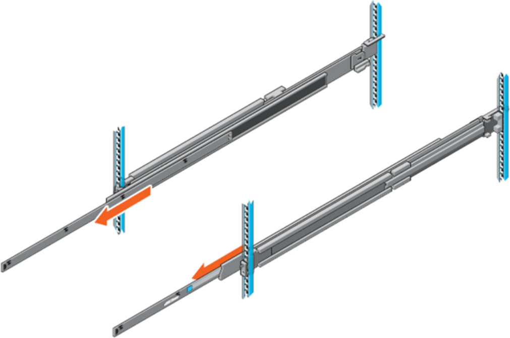
Installing the Appliance in Rack
-
Pull the inner rails out of the rack until they lock into place.
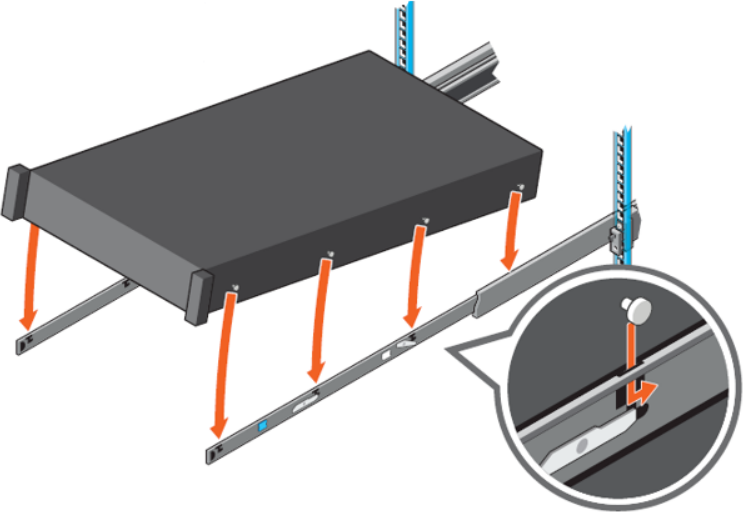
-
Locate the rear rail standoff on each side of the system and lower them into the rear J-slots on the slide assemblies.
-
Rotate the system downward until all the rail standoffs are seated in the J-slots.
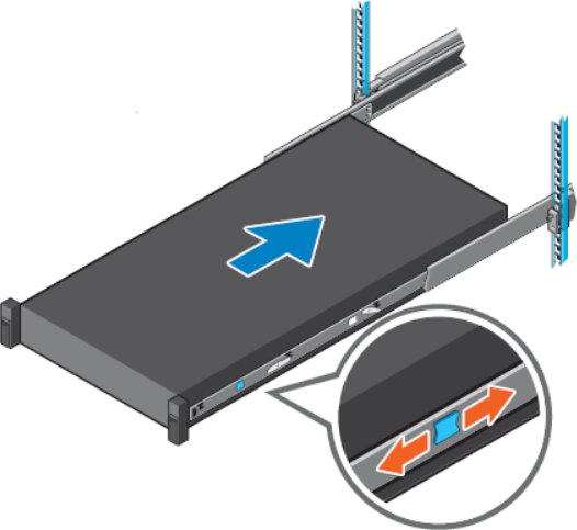
-
Push the system inward until the lock levers click into place.
-
Pull the blue side release lock tabs forward or backward on both rails and slide the system into the rack until the system is in the rack.
-
Ground the appliance (see "Grounding the Appliance").
-
Plug in the power cables (see "Hardware Installation | HardwareInstallation PowerConnectionsandInitialPowerOn").
-
Push the ON/OFF button to start.
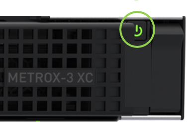
-
Check the Status LEDs and confirm that all of the LEDs show status lights consistent with normal operation.
Any amber status LEDs are a cause for concern and must be dealt with immediately. It can take up to 5 minutes to boot up, during which time the status LED may indicate red.
Rack Mount Instructions (similar rack-mount instructions are included with the installation instructions):
-
Elevated Operating Ambient—If installed in a closed or multi-unit rack assembly, the operating ambient temperature of the rack environment may be greater than the room ambient. Therefore, consideration should be given to installing the equipment in an environment compatible with the maximum ambient temperature (Tma) specified by the manufacturer.
-
Reduced Air Flow— Installation of the equipment in a rack should be such that the amount of airflow required for the safe operation of the equipment is not compromised.
-
Mechanical Loading—Mounting of the equipment in the rack should be such that a hazardous condition is not achieved due to uneven mechanical loading.
-
Circuit Overloading—Consideration should be given to the connection of the equipment to the supply circuit and the effect that overloading of the circuits might have on overcurrent protection and supply wiring. Appropriate consideration of equipment nameplate ratings should be used when addressing this concern.
-
Reliable Earthing—Reliable earthing of rack-mounted equipment should be maintained. Particular attention should be given to supply connections other than direct connections to the branch circuit (e.g., use of power strips).
-
Please note that the handlebar and mounting ear must be installed after the slide rail kit has been installed completely.
Connecting the Appliance to the Network/Fabric
The appliance requires both InfiniBand and Ethernet (out-of band management) connectivity where eth0 should be connected to a management network switch, and both InfiniBand ports should be connected to InfiniBand switches. They can be connected to the same switch, but NVIDIA recommends connecting to two separate switches to ensure SM connectivity to the fabric.
Grounding the Appliance
Check to determine if your local or national electrical codes require an external ground to all IT components. If so, connect a ground wire to one of the casing screws and connect the other end to a valid ground. If you choose not to use the ground screw, make sure that the rack is properly grounded and that there is a valid ground connection between the chassis of the appliance and the rack. Test the ground using an Ohm meter.
Some national and/or local codes may require IT components to be bonded and externally grounded (not including the power cord ground). You must follow all national and local codes when installing this equipment.
Power Connections and Initial Power On
The system is shipped with two power supply units. Each unit has a separate AC receptacle. The system accepts input voltages of 100 - 127 VAC and 200 - 240 VAC for all possible PS units. The power cords should be standard 3-wire AC power cords including a safety ground and rated for 15A or higher. The power supplies deliver 750W AC.
After inserting a power cable and turning the appliance on, confirm that the green system status LED light is on.
When turning off the system, make sure both connector LEDs are off to ensure a powered down status.
Do not hot swap the power supply if your appliance has only one power supply. You must power down the system to replace the power supply unit there is only one PS unit in the appliance.
Extracting and Inserting the Power Supply Unit
Two Power Inlets - Electric Caution Notifications
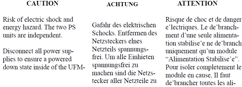
The power supply is only hot-swappable if you have a redundant system with two power supplies installed. If you only have one power supply installed, before removing or replacing the power supply, you must first:
-
Make sure the system is out of service.
-
Turn off all peripheral devices connected to the system.
-
Turn the system off by pressing the power button.
-
Unplug the AC power cord from the system or wall outlet.
To replace the power supply, follow these steps:
-
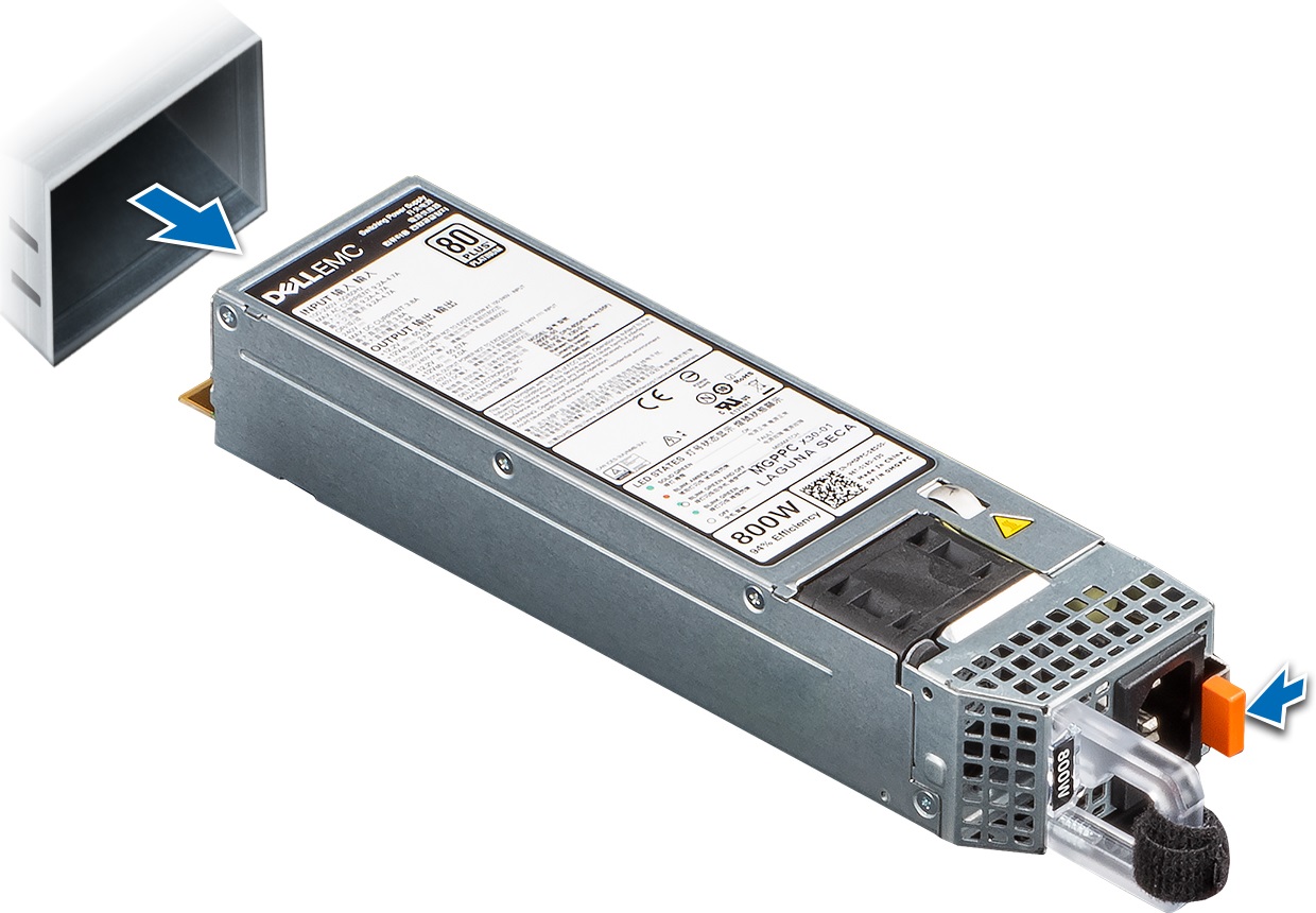
Disconnect the power cable from the power outlet and from the PSU you intend to remove.
-
Remove the cable from the strap on the PSU handle.
-
Unlatch and lift the optional cable management arm if it interferes with the PSU removal.
-
Press and hold the PSU latch while sliding the PSU out:
-
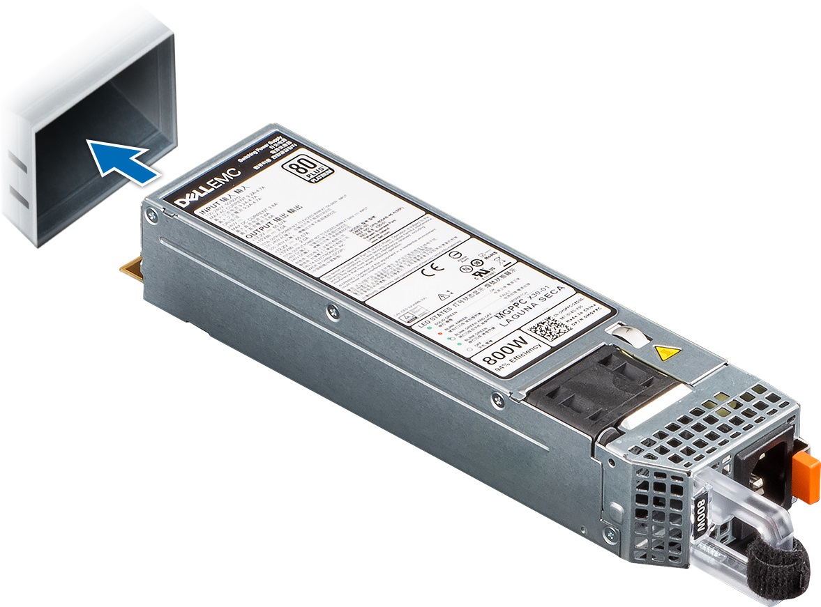
Slide the new PSU in:
-
If you have unlatched the cable management arm, re-latch it.
-
Connect the power cable to the PSU and plug the cable into a power outlet.
When connecting the power cable to the PSU, secure the cable to the PSU with the strap.
When installing, hot swapping or hot adding a new PSU, wait 15 seconds for the system to recognize the PSU and determine its status. PSU redundancy may not occur until discovery is complete. The PSU status indicator turns green to indicate that the PSU is functioning properly.
Do not run the system with openings of missing parts. This may cause overheating due to improper air flow.
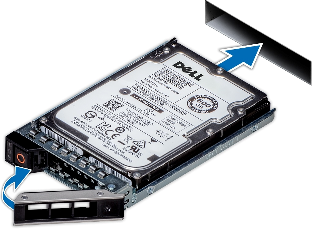
Replacing the SSD
Never pull out a working hard drive while the appliance is turned on. You can safely pull out a faulty hard drive indicated by a solid amber light.
If one SSD physically fails, the appliance keeps working thanks to RAID mirroring. You can pull out and replace a faulty drive with a new blank SSD. The blank SSD will synchronize with the other SSD. This takes up to 48 hours but does not interrupt appliance operation.
-
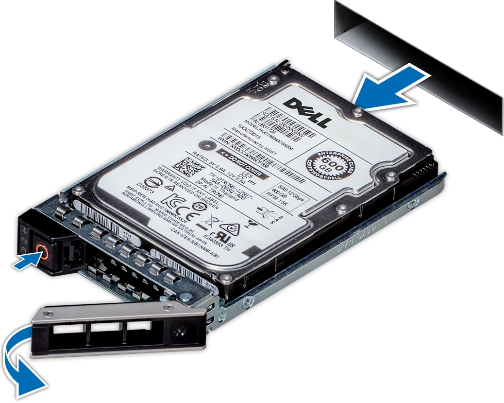
Power down the appliance before removing the SSD
-
Press the release button to open the drive carrier release handle.
-
Holding the drive carrier release handle, slide the drive carrier out of the drive slot.
-
Remove the SSD from its carrier drawer.
-
Hold the release handle and slide the drive carrier into the drive slot.
-
Close the drive carrier release handle to lock the drive in place.
-
Power on the appliance.
The SW RAID mechanism will identify that a new SSD was inserted and synchronize the data with the second SSD, this process might take up to 48 hours to complete.
Disassembly of the System from the Rack
To disassemble the appliance from the rack:
-
Shut down the system.
-
Unplug and remove all connectors.
-
Unplug all power cords.
-
Remove the ground wire.
-
Unscrew the 2 center bolts from inside the handles.
-
Slide the appliance from the rack.
-
Remove the rail slides from the rack.
Removing the Battery
NVIDIA does not support battery replacement. Customer removal of the cover will void the warranty. Remove the cover only to comply with WEEE directives or to disassemble the appliance for environmentally approved disposal.
This procedure is only to be used when you are disassembling this appliance before discarding, to comply with regulations regarding disposal of batteries.
-
Remove the cover.
-
Remove the battery and dispose of it according to local, state and federal regulations.
Disposal

Cable Installation
Power Cable
The NVIDIA MetroX-3 XC appliance is shipped with two power supply units. Each unit has a separate AC receptacle. The appliance accepts voltages of 100-127 VAC and 200-240 VAC for all possible power supply units. The power cords should be a standard 3-wire AC power cards, including a safety ground, and rated for 15A or higher. The power supplies deliver 2KW AC.
After inserting a power cable and turning the appliance on, confirm the green system LED light is on.
Do not hot swap the power supply if your appliance has only one power supply. Instead, power down the system to replace the power supply unit.
ConnectX-7 Networking Cards Cables
Networking Cable Installation
All cables can be inserted or removed with the unit powered on. To insert a cable, press the connector into the port receptacle until the connector is firmly seated.
-
Support the weight of the cable before connecting the cable to the adapter card. Do this by using a cable holder or tying the cable to the rack.
-
Determine the correct orientation of the connector to the card before inserting the connector. Do not try and insert the connector upside down. This may damage the adapter card.
-
Insert the connector into the adapter card. Be careful to insert the connector straight into the cage. Do not apply any torque, up or down, to the connector cage in the adapter card.
-
Make sure that the connector locks in place.
When installing cables, make sure that the latches engage.
Always install and remove cables by pushing or pulling the cable and connector in a straight line with the card.
-
After inserting a cable into a port, the green LED indicator will light when the physical connection is established (that is, when the unit is powered on and a cable is plugged into the port with the other end of the connector plugged into a functioning port). See Network Interface Cards LEDs under the Interfaces section.
-
After plugging in a cable, lock the connector using the latching mechanism particular to the cable vendor. When data is being transferred, the green LED will blink.
-
Care should be taken to not impede the air exhaust flow through the ventilation holes. Use cable lengths that allow for routing horizontally around to the side of the chassis before bending upward or downward in the rack.
-
To remove a cable, disengage the locks and slowly pull the connector away from the port receptacle. The LED indicator will turn off when the cable is unseated.
All cables can be inserted or removed with the unit powered on. To insert a cable, press the connector into the port receptacle until the connector is firmly seated. The LED indicator, corresponding to each data port, will light up when the physical connection is established. When a logical connection is made, the relevant port LED will turn on. To remove a cable, disengage the locks and slowly pull the connector away from the port receptacle. The LED indicator for that port will turn off when the cable is unseated. For full cabling guidelines, ask your NVIDIA Networking representative for a copy of NVIDIA Cable Management Guidelines and FAQs Application Note.
Do not force the cable into the cage with more than 40 newtons/9.0 pounds/4kg of force. Greater insertion force may cause damage to the cable or to the cage.
Initial Power-On
The system’s input voltage is specified in the Technical Specifications chapter. The power cords should be a standard 3-wire AC power cords including a safety ground and rated for 15A or higher.
The system platform will automatically power on when AC power is applied. There is no power system. Check all boards, power supplies and fans for proper insertion before plugging in a power cable.
Step 1. Plug in the first power cable.
Step 2. Plug in the second power cable.
Step 3. Wait for the System Status LED to turn green.
It may take up to five minutes to turn on the system. If the System Status LED is red after five minutes, unplug the system and call your NVIDIA Networking representative for assistance.
Step 4. Check the System Status LEDs and confirm that all of the LEDs show status lights consistent with normal operation (initially flashing, and then moving to a steady color). For more information, refer to System Monitoring.
After inserting a power cable and confirming the green System Status LED light is on, make sure that the Fan Status LED is green. If the Fan Status LED is not green, unplug the power connection, and check that the fan module is inserted properly and that the mating connector of the fan unit is free of any dirt and/or obstacles. If no obstacles were found and the problem persists, call your NVIDIA Networking representative for assistance.
Last updated: