Absolute Maximum Specifications
Absolute maximum ratings are those beyond which damage to the device may occur.
Prolonged operation between the operational specifications and absolute maximum ratings is not intended and may cause permanent device degradation.
|
Parameter |
Symbol |
Min |
Max |
Units |
|
Storage Temperature |
TS |
-40 |
85 |
°C |
|
Operating Case Temperature |
TOP |
0 |
70 |
°C |
|
Supply Voltage |
Vcc |
-0.5 |
4.0 |
V |
|
Relative Humidity (non-condensing) |
RH |
15 |
85 |
% |
|
Receiver Damage Threshold, per Lane |
PRdmg |
5 |
|
dBm |
-
Transceiver performance is guaranteed above 15°C.
-
Module temperature per DDMI readout of up to 75°C is allowed with a potential power consumption increase by maximum of 0.5W.
-
To be connected to switches with reverse air flow only.
Recommended Operating Conditions and Power Supply Requirements
|
Parameter |
Symbol |
Min |
Typ |
Max |
Units |
|
Power Supply Voltage |
Vcc |
3.135 |
3.3 |
3.465 |
V |
|
Maximum Power Dissipation |
PD |
- |
- |
17 |
W |
|
Signaling Rate per Lane |
SRL |
- |
53.125 |
- |
Gbd |
|
Operating Distance |
- |
- |
- |
500 |
m |
Electrical Specifications
|
Parameter |
Symbol |
Min |
Typ |
Max |
Units |
|
Receiver (Module Output) |
|||||
|
Signaling rate per lane |
|
53.125 |
Gbd |
||
|
AC common-mode output voltage (RMS) |
|
|
|
|
|
|
Differential output Voltage |
|
- |
- |
17.5 |
mV |
|
Eye height, differential |
|
15 |
- |
- |
mV |
|
Vertical eye closure |
|
|
|
12 |
dB |
|
Common-mode to differential return loss |
|
Equation (120G-1) |
dB |
||
|
Effective return loss, ERL |
|
8.5 |
|
|
dB |
|
Differential Termination Mismatch |
|
- |
- |
10 |
% |
|
Transition Time (min, 20% to 80%) |
|
8.5 |
- |
- |
ps |
|
DC common mode Voltage (Generated by host. Specification includes effects of ground offset voltage.) |
|
-350 |
- |
2850 |
mV |
|
Transmitter (Module Input) |
|||||
|
Signaling rate per lane |
|
53.125± 100 ppm |
Gbd |
||
|
Differential pk-pk input Voltage tolerance |
|
900 |
- |
- |
mV |
|
Differential to common mode input return loss |
|
Per equation (120G-2) IEEE802.3ck |
dB |
||
|
Effective return loss, ERL |
|
8.5 |
|
|
dB |
|
Differential termination mismatch |
|
- |
- |
10 |
% |
|
Module stress input test |
|
Per 120G.3.4.1,
|
|
||
|
Single-ended voltage tolerance range |
|
-0.4 |
- |
3.3 |
V |
|
DC common mode Voltage (Generated by host. Specification includes effects of ground offset voltage.) |
|
-350 |
- |
2850 |
mV |
Notes:
Amplitude customization beyond these specs is dependent on validation in customer system.
Optical Specifications
|
Parameter |
Symbol |
Min |
Typ |
Max |
Unit |
Notes |
|
Transmitter |
||||||
|
Signaling rate (each lane) (range) |
|
53.125 ± 100 ppm |
GBd |
|
||
|
Modulation format |
|
PAM4 |
|
|
||
|
Wavelength (range) |
λC |
1304.5 |
1311 |
1317.5 |
nm |
|
|
Side Mode Suppression Ratio |
SMSR |
30 |
- |
- |
dB |
|
|
Average Launch Power, each lane |
AOPL |
-2.9 |
- |
4.0 |
dBm |
1 |
|
Outer Optical Modulation Amplitude (OMAouter), each lane |
TOMA |
-3.0 |
- |
4.2 |
dBm |
2 |
|
Launch Power in terms of OMAouter minus TDECQ, each lane |
OMAouter |
-2.2 |
- |
- |
dBm |
|
|
Transmitter and Dispersion Eye Closure for PAM4, each lane |
TDECQ |
- |
- |
3.4 |
dB |
|
|
Average Launch Power of OFF Transmitter, each lane |
TOFF |
- |
- |
-15 |
dBm |
|
|
Extinction Ratio, each lane |
ER |
3.5 |
|
|
dB |
|
|
RIN21.4OMA |
RIN |
- |
- |
-136 |
dB/Hz |
|
|
Optical Return Loss Tolerance |
ORL |
- |
- |
21.4 |
dB |
|
|
Transmitter Reflectance |
TR |
- |
- |
-26 |
dB |
3 |
|
Receiver |
||||||
|
Signaling rate, each lane (range) |
|
53.125 ± 100 ppm |
GBd |
|
||
|
Modulation format |
|
PAM4 |
|
|
||
|
Wavelength (range) |
λC |
1304.5 to 1317.5 |
nm |
|
||
|
Damage Threshold, average optical power, each lane |
AOPD |
5 |
dBm |
4 |
||
|
Average Receive Power, each lane |
AOPR |
-5.9 |
- |
4.0 |
dBm |
5 |
|
Receive Power (OMAouter), each lane |
OMA-R |
- |
- |
4.2 |
dBm |
|
|
Receiver Reflectance |
RR |
- |
- |
-26 |
dB |
|
|
Receiver Sensitivity (OMAouter), each lane |
SOMA |
- |
- |
-4.4 |
dBm |
6 |
|
Stressed Receiver Sensitivity (OMAouter), each lane |
SRS |
- |
- |
-1.9 |
dBm |
7 |
|
Conditions of stressed receiver sensitivity test: |
||||||
|
Stressed eye closure for PAM4 (SECQ) |
|
3.4 |
dB |
8 |
||
|
OMAouter of each aggressor lane |
|
4.2 |
dBm |
|
||
Notes:
-
Average launch power, each lane (min) is informative and not the principal indicator of signal strength.
-
Even if TDECQ < 1.4dB, OMAouter (min) must exceed this value.
-
Transmitter reflectance is defined looking into the transmitter.
-
Receiver shall be able to tolerate, without damage, continuous exposure to an optical input signal having this average power level.
-
Average receive power, each lane (min) is informative and not the principal indicator of signal strength. A received power below this value cannot be compliant; however, a value above this does not ensure compliance.
-
Receiver sensitivity (OMAouter), each lane (max) is informative and is defined for a transmitter with SECQ of 0.9 dB.
-
Measured with conformance test signal at TP3 for the BER = 2.4x10⁻⁴.
-
These test conditions are for measuring stressed receiver sensitivity. They are not characteristics of the receiver.
Mechanical Specifications
Finned-top Twin-port for air-cooled Quantum-2 InfiniBand or Spectrum-4 Ethernet Switches: Bottom, Side, and Top Views:
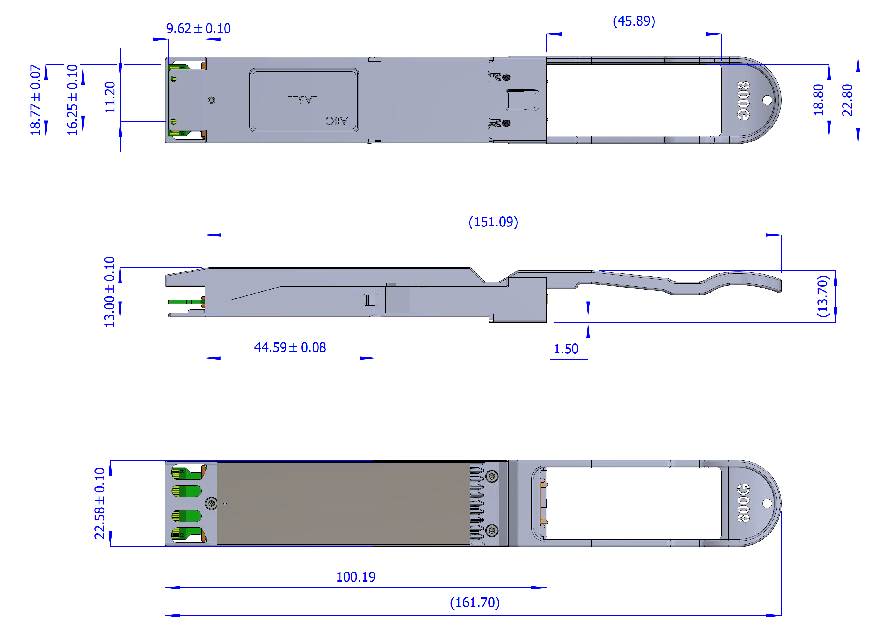
Images are for illustration purposes only. Product labels, colors, and form may vary.
Labels
Back shell Label
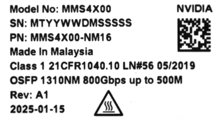
Images are for illustration purposes only. Product labels, colors, and form may vary.
Transceiver Back-Shell Label Serial Number Legend
|
Symbol |
Meaning |
Notes |
|
MT |
Manufacturer name |
2 digits (alphanumeric) |
|
YY |
Year of manufacturing |
2 last digits of the year (numeric) |
|
WW |
Week of manufacturing |
2 digits (numeric) |
|
DM |
Manufacturer site |
Two characters |
|
SSSSS |
Serial number |
5 digits (decimal numeric) for serial number, starting from 00001. |
Regulatory Compliance
The transceiver is a Class 1 laser product. It is certified per the following standards:
|
Feature |
Agency |
Standard |
|
Laser Eye Safety |
FDA/CDRH |
CDRH 21 CFR 1040 and Laser Notice 56 |
|
Laser Eye Safety |
UL |
IEC 60825-1:2014 IEC 60825-2: 2004+A1+A2 |
|
Electrical Safety |
CB |
IEC 62368-1:2018 |
|
Electrical Safety |
UL/CSA |
CLASS 3862.07
|
Connector and Cabling Details
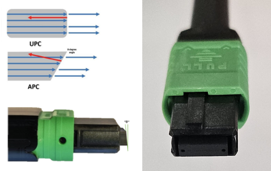
MPO-16/APC Optical Connector
The single-port NDR transceiver has a unique NVIDIA patented design enabling, multiple-push-on/angled-polished-connector 16-fiber (MPO-16/APC) optical connectors per single OSFP form-factor by turning the optical connectors vertically in the twin-port transceiver end. This enables it to host two NDR transceivers inside, each with its own MPO-16/APC optical connector operating independently that can link to another single-port 800Gb/s NDR transceiver.
The MPO-16 has a 16-fiber ribbon where 16-fibers are used – eight transmit and eight receive fibers for the 8-channels 100G-PAM4.
-
The APC design minimizes back reflections and signal interference by diverting back reflected light from the fiber face to be absorbed into the fiber cladding.
-
A positioning key on top of the connector together with the alignment pins define the fiber position numbering scheme to align pin 1 in the optical connector to pin 1 in the transceiver also called “polarity”
-
Transceivers have alignment pins for precise positioning of the cable connector against the optical beams. The fiber cable has alignment holes matching the transceiver’s pins.
-
Important to note that transceivers have pins. Optical connectors have holes used with transceivers have holes. Optical connectors with pins are not compatible with transceivers and used in trunk cabling to connect two fiber cables together.
The MPO-16/APC optical connector is used in both the 100G-PAM4 based single mode and multimode fiber cables.
Single mode optics is denoted by a yellow-colored pull tab and yellow-colored optical fiber. Green plastic shell on the MPO-16/APC connector denotes Angled Polish Connector and is not compatible with Ultra-flat Polished Connectors (UPC) used with slower line rate transceivers.
MPO-16/APC Showing 8-Transmit and 8-Receive Fibers and Angled Polish Connector End face
Last updated: