QSFP28 Pin Description
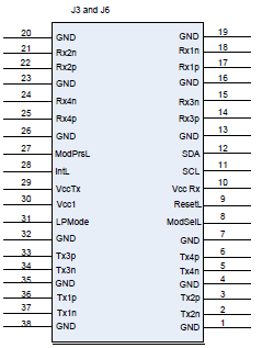
QSFP Pin Description
|
Connector Pin Number |
Symbol |
Signal Description |
|---|---|---|
|
1 |
GND |
Ground |
|
2 |
Tx2n |
Connected to Port 2 lane Rx
|
|
3 |
Tx2p |
Connected to Port 2 lane Rx
|
|
4 |
GND |
Ground |
|
5 |
Tx4n |
Connected to Port 4 lane Rx
|
|
6 |
Tx4p |
Connected to Port 4 lane Rx
|
|
7 |
GND |
Ground |
|
8 |
Mod-SelL |
Cable/Module Select |
|
9 |
ResetL |
Cable/Module Reset |
|
10 |
Vcc Rx |
+3.3 V Power supply receiver |
|
11 |
SCL |
2-wire serial interface clock |
|
12 |
SDA |
2-wire serial interface data |
|
13 |
GND |
Ground |
|
14 |
Rx3p |
Connected to Port 3 lane Tx
|
|
15 |
Rx3n |
Connected to Port 3 lane Tx
|
|
16 |
GND |
Ground |
|
17 |
Rx1p |
Connected to Port 1 lane Tx
|
|
18 |
Rx1n |
Connected to Port 1 lane Tx
|
|
19 |
GND |
Ground |
|
20 |
GND |
Ground |
|
21 |
Rx2n |
Connected to Port 2 lane Tx
|
|
22 |
Rx2p |
Connected to Port 2 lane Tx
|
|
23 |
GND |
Ground |
|
24 |
Rx4n |
Connected to Port 4 lane Tx
|
|
25 |
Rx4p |
Connected to Port 4 lane Tx
|
|
26 |
GND |
Ground |
|
27 |
ModPrsL |
Module/cable Present |
|
28 |
IntL |
Interrupt |
|
29 |
Vcc Tx |
+3.3 V Power supply transmitter |
|
30 |
Vcc 1 |
+3.3 V Power Supply |
|
31 |
LPMode |
Low Power Mode |
|
32 |
GND |
Ground |
|
33 |
Tx3p |
Connected to Port 3 lane Rx
|
|
34 |
Tx3n |
Connected to Port 3 lane Rx
|
|
35 |
GND |
Ground |
|
36 |
Tx1p |
Connected to Port 1 lane Rx
|
|
37 |
Tx1n |
Connected to Port 1 lane Rx
|
|
38 |
GND |
Ground |
SFP28 Pin Description
Rear View of Module with Pin Placement
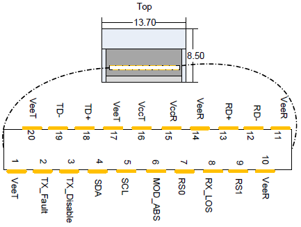
SFP Pin Description
|
Pin |
Symbol Name |
Description |
Note |
|---|---|---|---|
|
1 |
VeeT |
Module Transmitter Ground |
-- |
|
2 |
TX_Fault |
Module Transmitter Fault |
a |
|
3 |
TX_Disable |
Transmitter Disable. Turns off transmitter laser output |
b |
|
4 |
SDA |
2-wire Serial Interface Data Line |
c |
|
5 |
SCL |
2-wire Serial Interface Clock Line |
d |
|
6 |
MOD_ABS |
Module Absent. Grounded within the module |
d |
|
7 |
RS0 |
No connection required |
-- |
|
8 |
Rx_LOS |
Loss of Signal indication. Logic 0 indicates normal operation. |
d |
|
9 |
RS1 |
No connection required |
-- |
|
10 |
VeeR |
Receiver Ground (Common with Transmitter Ground) |
a |
|
11 |
VeeR |
Receiver Ground (Common with Transmitter Ground) |
a |
|
12 |
RD- |
Receiver Inverted DATA out. AC Coupled |
-- |
|
13 |
RD+ |
Receiver Non-inverted DATA out. AC Coupled |
-- |
|
14 |
VeeR |
Receiver Ground (Common with Transmitter Ground) |
a |
|
15 |
VccR |
Receiver Power Supply |
-- |
|
16 |
VccT |
Transmitter Power Supply |
-- |
|
17 |
VeeT |
Transmitter Ground (Common with Receiver Ground) |
a |
|
18 |
TD+ |
Transmitter Non-Inverted DATA in. AC Coupled |
-- |
|
19 |
TD- |
Transmitter Inverted DATA in. AC Coupled |
-- |
|
20 |
VeeT |
Transmitter Ground (Common with Receiver Ground) |
a |
Notes:
-
-
TFAULT is an open collector/drain output, which should be pulled up with a 4.7k-10k Ohms resistor on the host board if intended for use. Pull up voltage should be between 2.0V to Vcc + 0.3V. A high output indicates a transmitter fault caused by either the TX bias current or the TX output power exceeding the preset alarm thresholds. A low output indicates normal operation. In the low state, the output is pulled to <0.8V.
-
Laser output disabled on TDIS >2.0V or open, enabled on TDIS <0.8V
-
Should be pulled up with 4.7kΩ-10kΩ on host board to a voltage between 2.0V and 3.6V. MOD_ABS pulls line low to indicate module is plugged in.
-
LOS is open collector output. Should be pulled up with 4.7kΩ-10kΩ on host board to a voltage between 2.0V and 3.6V. Logic 0 indicates normal operation; logic 1 indicates loss of signal.
-
RJ-45 CONSOLE and I²C Interface
RJ-45 Console and I²C interfaces are integrated in the same connector. Due to that, connecting any cable other than the Mellanox supplied console cable may cause an I²C hang.
Using uncertified cables may damage the I²C interface. Refer to the Replacement Parts Ordering Numbers appendix for harness details.
|
Signal |
Pin# |
Color |
|---|---|---|
|
Not connected |
1 |
G/W |
|
I²C_SCL |
2 |
G |
|
TXD |
3 |
O/W |
|
Not connected |
4 |
Bl |
|
GND |
5 |
Bl/W |
|
RXD |
6 |
O |
|
I²C_SDA |
7 |
Br/W |
|
Not connected |
8 |
Br |
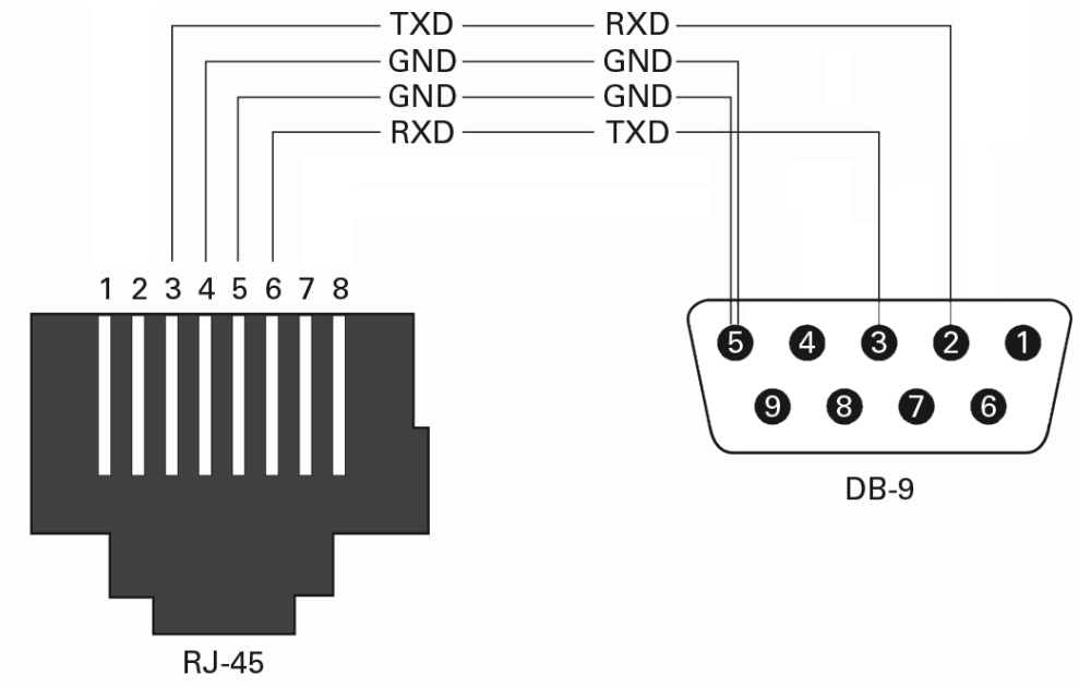
RJ45 to DB9 Harness Pinout
The RS232 harness cable (DB9 to RJ45) is provided within the package to connect a host PC to the system's Console RJ45 port.
RJ45 to DB9 Harness Pinout
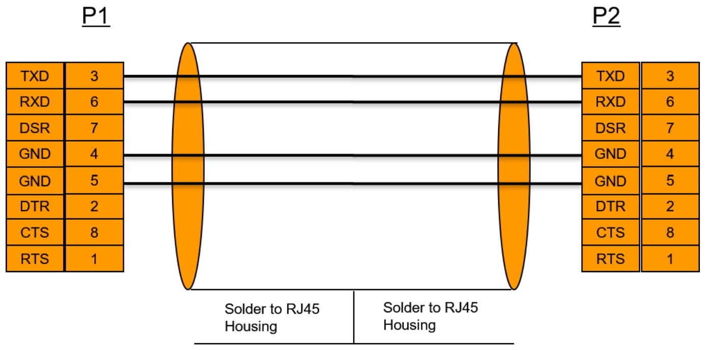
RJ45 to RJ45 Harness
2m RJ45-to-RJ45 serial port cable is provided in the SN2410 and SN2700 packages.
The harness must be used when connecting the switch serial port with the terminal server/console server.
The new harness can be extended by an ordinary flat 1-to-1 RJ45 cable.
Last updated: