

The system’s LEDs are an important tool for hardware event notification and troubleshooting. All figures depicted on this page are for illustration purposes only; the designs may vary slightly between systems.
LED Symbols
|
Symbol |
Name |
Description |
Normal Conditions |
|---|---|---|---|

|
Shows the health of the system. |
Green or flashing green when booting |
|

|
Shows the health of the fans. |
Green |
|

|
Shows the health of the power supply units. |
Green |
|

|
Shows the an aggregated state of all ELS modules. |
Green |
|

Or 
|
Lights up on command through the CLI. |
Off or blue when activated by the user |
*Applies to SN6600 systems only. All other systems in this series are cooled by a liquid cooling mechanism.
System Status LED
The LED illuminated green in the figure below indicates the system’s status
|
Front (Ports Side): 
|
It can take up to five minutes for the booting process to complete. If the System Status LED displays amber after five minutes, unplug the system and contact your NVIDIA representative for assistance.
System Status LED Descriptions
|
LED |
Description |
Action Required |
|---|---|---|
|
Solid green |
The system is up and running normally. |
N/A |
|
Flashing green |
The system is booting up. |
Wait up to five minutes for the booting process to complete. |
|
Solid amber |
An error has occurred. For example, corrupted firmware, system is overheated, etc. |
If the System Status LED displays amber five minutes after starting the system, refer to Troubleshooting for further instructions. |
Fan Status LED
This section applies to the SN6600, AC powered air-cooled switch systems only.
Fan Status LED (Front and Rear Sides)
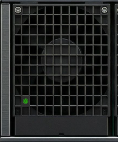
Both of the LEDs circled below indicate the fans’ status.
Front Panel LED:

Rear Panel LED
Fan Status Front LED Assignments
|
LED |
Description |
Action Required |
|---|---|---|
|
Solid green |
All fans are up and running |
N/A |
|
Solid amber |
One or more fans are not operating properly |
Replace the faulty FRUs |
Fan Status Rear LED Assignments (One LED per Fan)
|
LED |
Description |
Action Required |
|---|---|---|
|
Solid green |
A specific fan unit is fully operational |
N/A |
|
Solid amber |
A specific fan unit is missing or not operating properly |
Replace the fan unit |
Risk of Electric Shock! Do not insert objects into the fan module cavity.
Power Supply/Power Distribution Board Status LEDs
This section applies to the SN6600, AC powered air-cooled switch systems only.
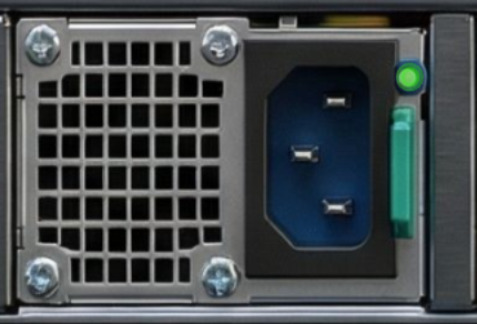
The LEDs below show the power supply/power distribution board status.
Front Panel LED:
Rear Panel LED:
-
The SN6600 switch model has eight power supply inlets for redundancy. The system can operate when at least two power supplies are connected. Each power supply unit has two single-color LEDs on the right side of the unit that indicate the status of the unit. When viewing the switch from the FRU side, the first power supply (PS) unit is located on the left side of the system, and the second unit is located on the right side.
-
The SN6600-LD, SN6800-LD and SN6810-LD are powered by DC busbars. The LED indicates the status of the busbar's distribution board.
Power Supply Unit/Power Distribution Board Status Front LED Assignments
|
LED Behavior |
Description |
Action Required |
|---|---|---|
|
Solid green |
All power supply units are connected and running normally. |
N/A |
|
Solid amber |
One or both of the power supplies are not operational or not powered up; the power cord is disconnected. |
Make sure the power cord is plugged in and operational. If the problem persists, refer to Troubleshooting. |
Power Supply Unit/Power Distribution Board Status Rear LED Assignments
|
LED Behavior |
Description |
Action Required |
|---|---|---|
|
Solid green |
The PSU is running normally. |
N/A |
|
Flashing green 1Hz |
AC Present, Standby (On), Main Output (Off) |
Refer to Troubleshooting. For further assistance, contact your NVIDIA representative. |
|
Flashing amber 1Hz |
PSU warning - events where the PSU continues to operate |
|
|
Solid amber |
PSU failure (voltage, current, temperature, or fan issue) |
|
|
Off |
No AC power to all power supplies. |
Plug in the AC cord |
Aggregated ELS Status LED
The below LED shows the combined status of all ELS modules.
It lights up green when all modules operate normally, and turns amber if one or more ELS modules fails to operate or goes offline, applicable in SN6810-LD and SN6800-LD.

Unit Identification LED
Blue LED that used to allocate a specific switch installed within a rack.
Activtaing and deactivating the UID LED is done via Network Operating System:
To activate the UID LED on a switch system, use the command:
switch (config) # led MGMT uid on
To verify the LED status, use command:
switch (config) # show ledsa
Module LED Status
--------------------------------------------------------------------------
MGMT UID Blues
To deactivate the UID LED on a switch system, use command:
switch (config) # led MGMT uid off
ETH Management Status LEDs
There are two ETH Management LEDs per system. Their behavior indicates link status or activity as follows:
|
LED Position |
LED Behavior |
Description |
|---|---|---|
|
Right LED |
Yellow (Steady) |
Link Up: A physical connection is established. |
|
Off |
Link Down: No physical connection detected. |
|
|
Left LED |
Green (Blinking) |
Activity: Indicates data traffic on the port. |
|
Green (Slow Blink) |
Low Traffic: Blinks approximately once per second. |
|
|
Green (Fast Blink) |
High Traffic: Blinks regularly several times per second. |
|
|
Off |
No Activity: No data is currently being transmitted/received. |
Port LEDs
The LEDs illuminated green in the figure below indicate the ports’ status. The exact location and shape of the ports and their LEDs may vary between systems.
Port LED Indications
|
State |
LED Behavior |
Description |
Action Required |
|---|---|---|---|
|
0 |
Off |
No 8×/4×/2×/1× link was established on this OSFP |
N/A |
|
Solid green |
At least one link was established: 8×/4×/2×A/2×B/1×A/1×B/1×C/1×D/1×E/1×F/1×G/1×H |
||
|
Flashing green |
Traffic is running in linked ports |
||
|
Flashing amber |
N/A |
||
|
1-8 |
Off |
Link is down |
|
|
Solid green |
Link is up with no traffic |
||
|
Flashing green |
Link is up with traffic |
||
|
Flashing amber |
A problem with the link |
|
Lane Selector LEDs
Each OSFP can be used as single port (8x - at 100G lanes only) or two 4× ports or four 2× ports;
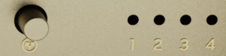
Each QSFP-DD/OSFP module has one dedicated bi-color LED, the will inidcate green light if one or more lane is successfully established a connection.
The LED splitting control button can be used to display link information of the different lanes. The lane select button lets you choose between 8 indication states: press the button to cycle through all 8 states. The current state can be identified by the LED splitting state indication LEDs. The states and their indications are detailed in the table below.
|
|
Lane Select LEDs |
|
|
|
LED Splitting Options
|
State |
State Indication LEDs
|
OSFP/QSFP-DD Module LED Indication |
Comments |
|---|---|---|---|
|
0 |

|
Any link is up |
See details in the Port LEDs Indications table below, state 0 |
|
1 |

|
8×/4×A/2×A/1×A |
|
|
2 |

|
8×/4×B/2×B/1×B |
|
|
3 |

|
8×/2×C/1×C |
|
|
4 |

|
8×/2×D/1×D |
Last updated: