Created on Feb 12, 2021
Updated on Jun 26, 2022
Introduction
This post describes how to install and configure NSX-T Data Center components, such as setting up the Transport Nodes, Edge VMs, configure Layer 2 Segments, Tier-0 uplinks and the routing required in preparation for vSphere with Tanzu.
This guide assumes the following hardware and software are installed:
-
NVIDIA Mellanox ConnectX-6 Lx SmartNIC Adapter with NATIVE ESXi driver version 4.21.71.101 and driver firmware version 26.33.1048
VMware ESXi, vSphere Cluster and vCenter install and configuration is out of the scope of this post.
Abbreviations and Acronyms
|
Term |
Definition |
Term |
Definition |
|---|---|---|---|
|
TEP |
Tunnel End Point |
VM |
Virtual Machine |
|
VDS |
NSX-managed Virtual Distributed Switch |
VTEP |
Virtual Tunnel End Point |
|
VLAN |
Virtual LAN |
|
|
References
-
How-to: Install NVIDIA Firmware Tools (MFT) on VMware ESXi 6.7/7.0.
-
How-to: NVIDIA ConnectX driver upgrade on VMware ESXi 6.7/7.0 and above.
-
How-to: Firmware update for NVIDIA ConnectX-5/6 adapter on VMware ESXi 6.5 and above.
VMware vSphere Distributed Switch
VMware vSphere Distributed Switch (VDS) provides a centralized interface from which you can configure, monitor and administer virtual machine access switching for the entire data center. The VDS provides simplified Virtual Machine network configuration, enhanced network monitoring and troubleshooting capabilities.
VMware NSX-T Data Center
VMware NSX-T™ Data Center provides an agile software-defined infrastructure to build cloud-native application environments.
NSX-T Data Center focuses on providing networking, security, automation, and operational simplicity for emerging application frameworks and architectures that have heterogeneous endpoint environments and technology stacks. NSX-T Data Center supports cloud-native applications, bare metal workloads, multi-hypervisor environments, public clouds, and multiple clouds.
NSX-T Data Center is designed for management, operation, and consumption by development organizations. NSX-T Data Center allows IT teams and development teams to select the technologies best suited for their applications.
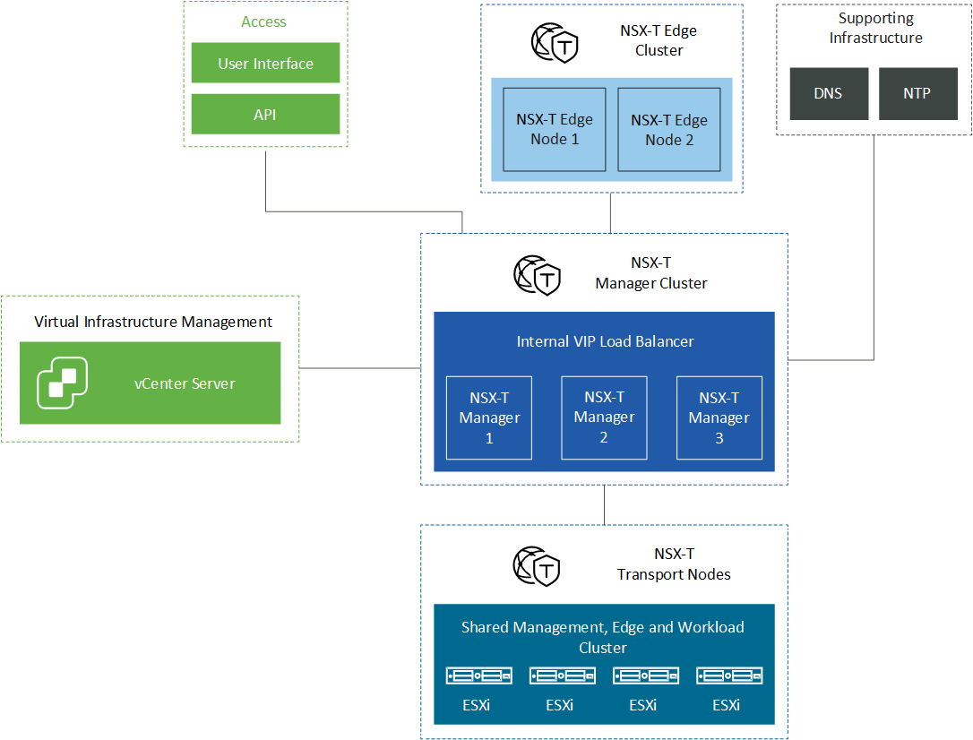
Solution Architecture
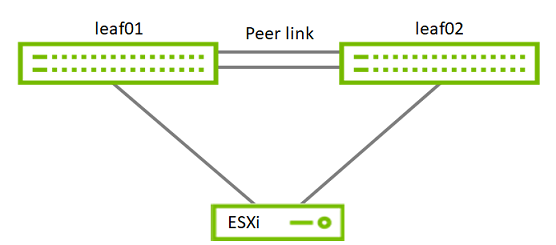
Logical Design
The simplest setup is used here: 4 ESXi servers connected to NVIDIA® Spectrum® SN2010 Ethernet switch.
Network Physical Connection
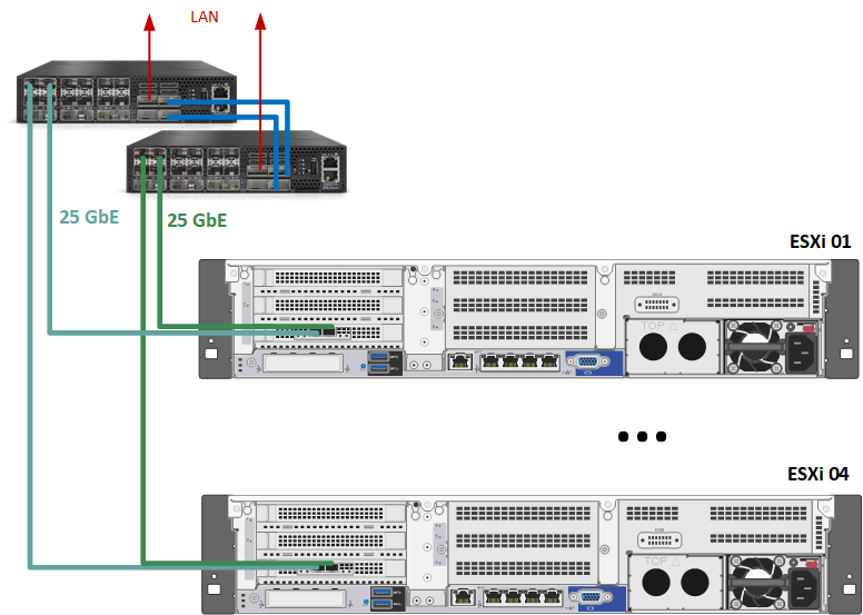
In our case, port 0 and 1 on ConnectX-6 Lx card on ESXi are presented as vmnic6 and vmnic7.
Network Configuration and Connection
vSphere Switches Design
Procedure
Network
Prerequisites
-
Switch Operating System
NVIDIA Cumulus 5.1 -
Management Network
DHCP and DNS services are required.
The components' installation and configuration are not covered in this guide.
Network Switch Configuration
ESXi to Leaf's connection
Port Channel and VLAN Configuration
Run the following commands on both Leaf NVIDIA SN2010 switches in the Supervisor Cluster to configure port channel and VLAN.
Sample for clx-swx-033 switch:
Switch console
cumulus@clx-swx-033:mgmt:~$sudo nv set interface swp7 link speed 1G
cumulus@clx-swx-033:mgmt:~$sudo nv set interface swp7 link mtu 1500
cumulus@clx-swx-033:mgmt:~$sudo nv set interface swp1-4 bridge domain br_default
cumulus@clx-swx-033:mgmt:~$sudo nv set interface swp7 bridge domain br_default
cumulus@clx-swx-033:mgmt:~$sudo nv set bridge domain br_default vlan 1611
cumulus@clx-swx-033:mgmt:~$sudo nv set bridge domain br_default vlan 1624-1625
cumulus@clx-swx-033:mgmt:~$sudo nv set interface vlan1 ip address 192.168.1.254/24
cumulus@clx-swx-033:mgmt:~$sudo nv set interface vlan1624 ip address 192.168.24.1/24
cumulus@clx-swx-033:mgmt:~$sudo nv set interface vlan1625 ip address 192.168.25.1/24
cumulus@clx-swx-033:mgmt:~$sudo nv set interface vlan1 link mtu 1500
cumulus@clx-swx-033:mgmt:~$sudo nv set vrf default router static 0.0.0.0/0 via 192.168.1.21
cumulus@clx-swx-033:mgmt:~$sudo nv config apply
cumulus@clx-swx-033:mgmt:~$sudo nv config save
The following configuration is on both Leaf NVIDIA SN2010 switches in the Supervisor Cluster to configure port channel and VLAN.
Sample for clx-swx-033 switch:
Hosts Preparation
Hosts in the Workload Cluster must be configured before an intensive data plane workload can be attached to the VDS switch.
To ensure optimal performance, do the following:
-
Configure BIOS for optimal performance
-
Enable CPU hyperthreading
-
Enable Turbo Boost
-
Disable NUMA node interleaving
-
Power Management: Set this setting to "High" or "Maximum Performance" (verbiage depending on vendor) to ensure that the CPUs always run at least at the base frequency and
use the shallowest idle. -
Enable Hyperthreading on the ESXi server: Enable this setting on systems that support it. Hyperthreading allows a single processor core to run two independent threads simultaneously. On processors with Hyperthreading, each core can have two logical threads that share the core's resources such as memory caches and functional units. BIOS providers might refer to the hyperthreaded core as a Logical Processor.
-
Turbo Boost: Enable this setting in the BIOS. It allows the processor to operate faster than the rated frequency for peak loads. For more information about Turbo Boost, see Frequently Asked Questions on the Intel Turbo Boost Technology page (posted on Intel's website).
-
NUMA Node Interleaving: Ensure that this setting is disabled. With the NUMA node interleaving setting enabled, the hypervisor sees the available memory as one contiguous
area. Therefore, the ability to place memory pages local to the CPU is lost and the hypervisor sees all resources on the host as local.
Network Adapter Driver and Firmware Update
To update firmware to version 26.33.1048 and driver to version 4.21.71.101, please refer to the following links:
-
How-to: Firmware update for NVIDIA ConnectX-5/6 adapter on VMware ESXi 6.5 and above
-
How-to: NVIDIA ConnectX driver upgrade on VMware ESXi 6.7/7.0 and above
Hosts Network Configuration
Prerequisites
-
vSphere WL01-Cluster01 clusters with VMware vSphere ESXi 7.0.3d is installed and configured. The cluster will be used for all workloads.
-
vCenter 7.0.3d or above
-
The installation requires administrator privileges on the target machine
-
Connection to ESXi host management interface
-
High speed network connectivity
Installation of vCenter, ESXi hosts, configuration of virtual DC, Clusters, and adding hosts to clusters are out of the scope of this document.
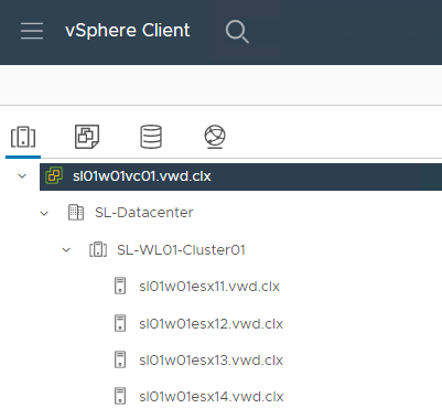
SL-WL01-Cluster01
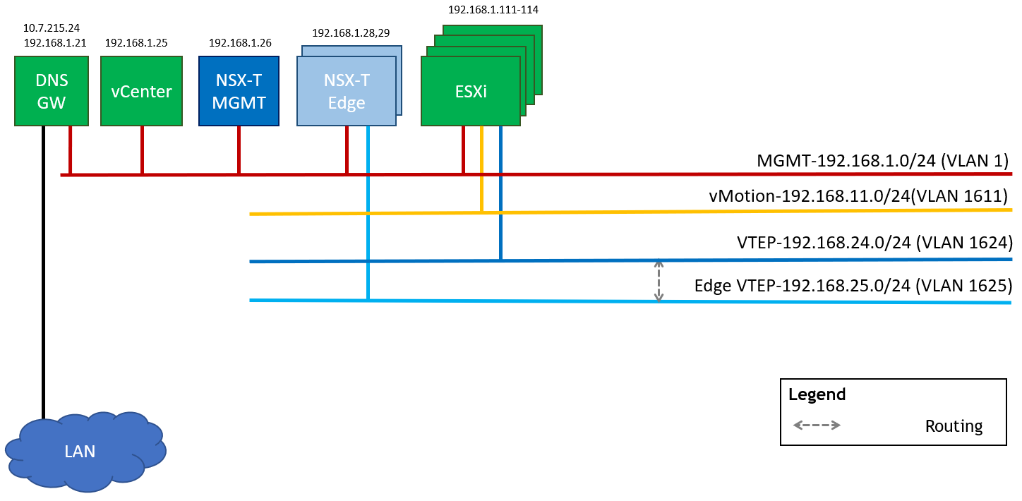
Networking
In the document I will going to use following networks.
-
Management Network (VLAN 1 – 192.168.1.0/24) – This is where the ESXi VMkernel interfaces and the management VMs will reside such as the NSX-T Manager and vCenter.
-
vMotion Network (VLAN 16 – 192.168.11.0/24) – This is where the ESXi vMotion VMkernel interfaces will reside.
-
NSX-T Geneve Overlay Network for ESXi Hosts (VLAN 1624 - 192.168.24.0/24) – This network will be used by the Geneve Overlay Tunnel endpoints VMkernel interfaces on the ESXi Hosts aka vmk10.
-
NSX-T Geneve Overlay Network for Edge VMs (VLAN 1625 – 192.168.25.0/24) – This network will be used by the Geneve Overlay Tunnel endpoints interfaces running in the Edge VMs.
This table provides details on the ESXi servers and switches in the SL-WL01-Cluster01, system names, and their network configurations.
|
Server |
Server Name |
IP and NICs |
|
|---|---|---|---|
|
Networks |
Management Network 192.168.1.0/24 (VLAN 1) |
||
|
ESXi-01 |
sl01w01esx11 |
vmk1: 192.168.11.111(vMotion - VLAN ) vmk10: From IP Pool 192.168.24.0/24 (NSX Host TEP) |
vmk0: 192.168.1.111 From DHCP (reserved) |
|
ESXi-02 |
sl01w01esx12 |
vmk1: 192.168.11.112(vMotion) vmk10: From IP Pool 192.168.24.0/24 (NSX Host TEP) |
vmk0: 192.168.1.112 From DHCP (reserved) |
|
ESXi-03 |
sl01w01esx13 |
vmk1: 192.168.11.113(vMotion) vmk10: From IP Pool 192.168.24.0/24 (NSX Host TEP) |
vmk0: 192.168.1.113 From DHCP (reserved) |
|
ESXi-04 |
sl01w01esx14 |
vmk1: 192.168.11.114(vMotion) vmk10: From IP Pool 192.168.24.0/24 (NSX Host TEP) |
vmk0: 192.168.1.114 From DHCP (reserved) |
|
Leaf-01 |
clx-swx-033 |
|
10.7.215.233 |
|
Leaf-02 |
clx-swx-034 |
|
10.7.215.234 |
|
vCenter (VM) |
sl01w01vc01 |
|
192.168.1.25 |
|
NSX-T Manager 01 (VM) |
sl01w01nsx01 |
|
192.168.1.26 |
|
NSX-T Edge 01 (VM) |
sl01w01nsxedge01 |
From IP Pool 192.168.25.0/24 (NSX Edge TEP) |
192.168.1.28 |
|
NSX-T Edge 02 (VM) |
sl01w01nsxedge02 |
From IP Pool 192.168.25.0/24 (NSX Edge TEP) |
192.168.1.29 |
|
NSX-T Edge Cluster |
EdgeCluster1 |
|
|
|
DNS/DHCP/AD/NTP/Bridge VM |
|
10.7.215.24 |
192.168.1.21 |
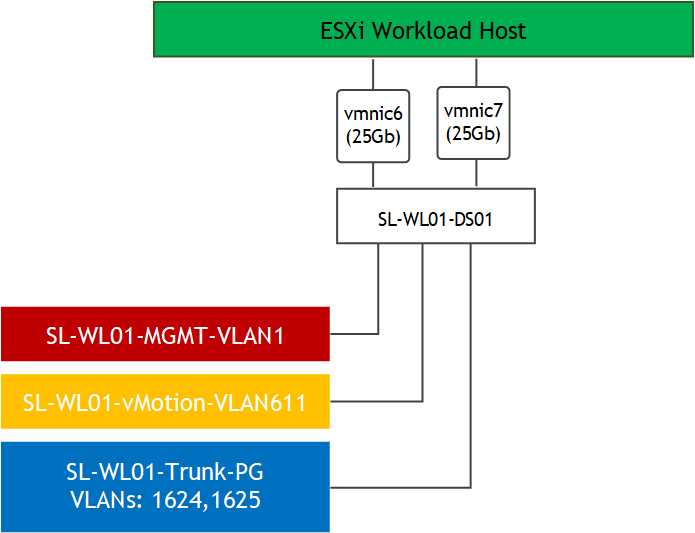
Configure a VDS
To configure a new VDS (sample - SL-WL01-DS01), with 2 Distributed Port Group (sample - SL-WL01-MGMT-VLAN1 and SL-WL01-vMotion-VLAN611) use the following document.
MTU size has been increased to 1600 or more than 1600. The recommended MTU is 9000.
VMware NSX-T Manager Installation and Configuration
Prerequisites
Below are the prerequisites for deploying NSX Manager.
-
Necessary resources exist on the cluster to deploy NSX-Manager appliance
-
Port group for Management network (it is preferable to keep on the same network as vCenter)
-
4 free IPs from management network for NSX Managers (in this guide only one appliance is deployed)
-
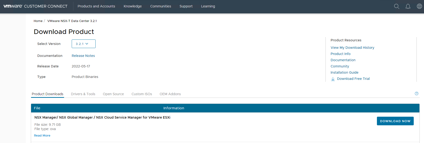
NSX Licenses and media OVA file downloaded from VMware website
-
Create DNS A rerecords for NSX-Manager Hostnames
Network Latency Requirements
-
The maximum network latency between NSX Managers in a NSX Manager cluster is 10ms
-
The maximum network latency between NSX Managers and Transport Nodes is 150ms
Storage Requirements
-
The maximum disk access latency is under 10ms
-
It is recommended that NSX Managers are placed on shared storage
-
Storage should be highly available to avoid a storage outage causing all NSX Manager file systems to be placed into read-only mode upon a storage failure event
Please see the documentation for your storage technology on how to optimally design a highly available storage solution.
Deployment
-
Download the NSX manager OVA from my.vmware.com.
-
Login to the vCenter.
-
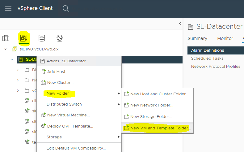
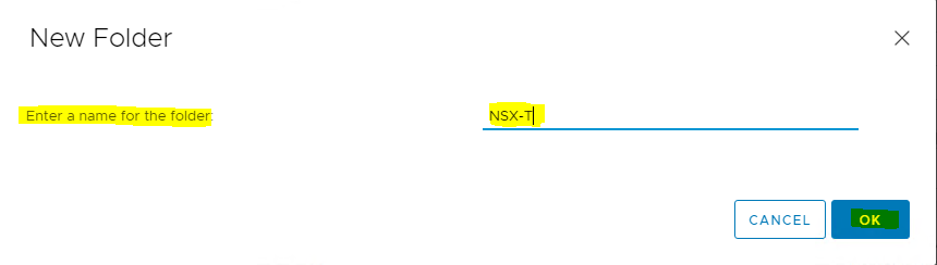
Click VMs and Templates → right click on the Datacenter folder (SL-Datacenter) → click New Folder → click New VM and Template Folder...
-
Assign Folder Name
-
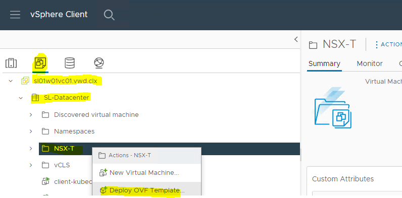
Click VMs and Templates → right click on the folder (NSX-T) where you would like the NSX-T Manager to be deployed → click Deploy OVF Template.
-
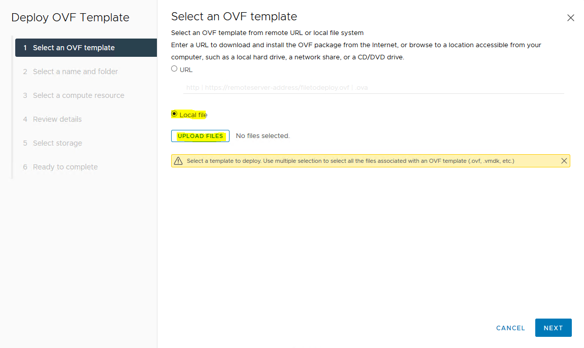
Select Local file → browse the OVA file for NSX Unified appliance → NEXT.

-
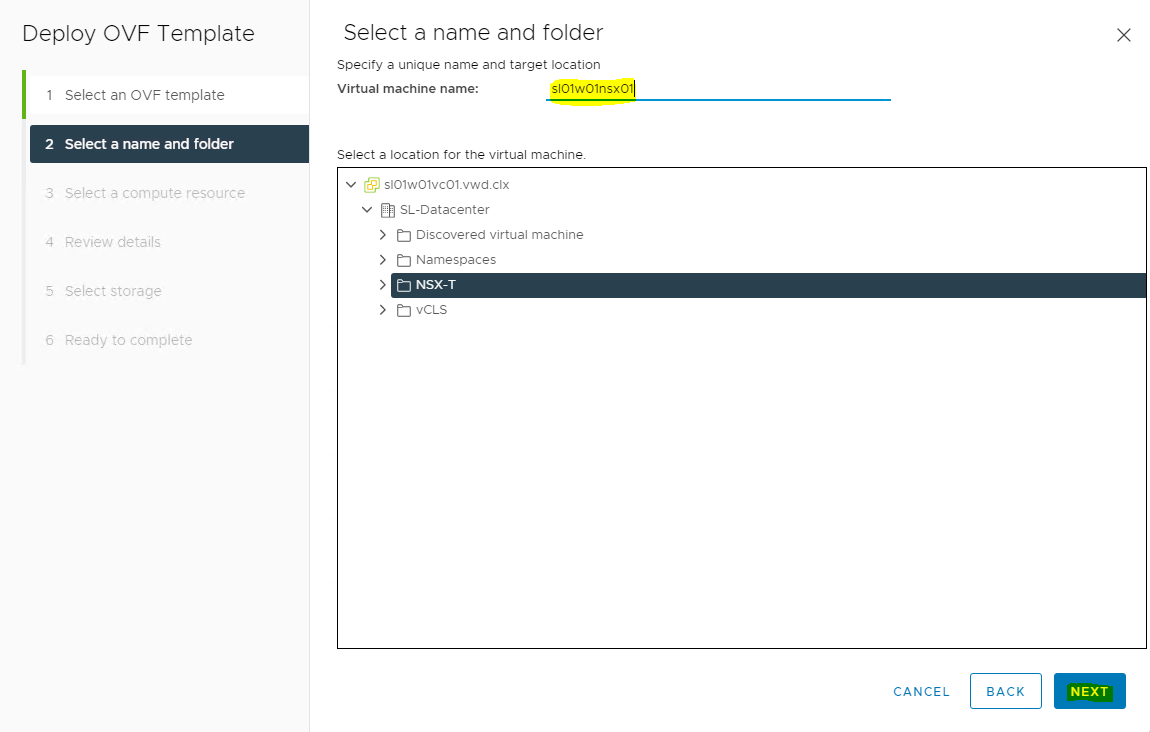
Assign Virtual machine name → select the folder in which you want to place the NSX manager → click NEXT.
-
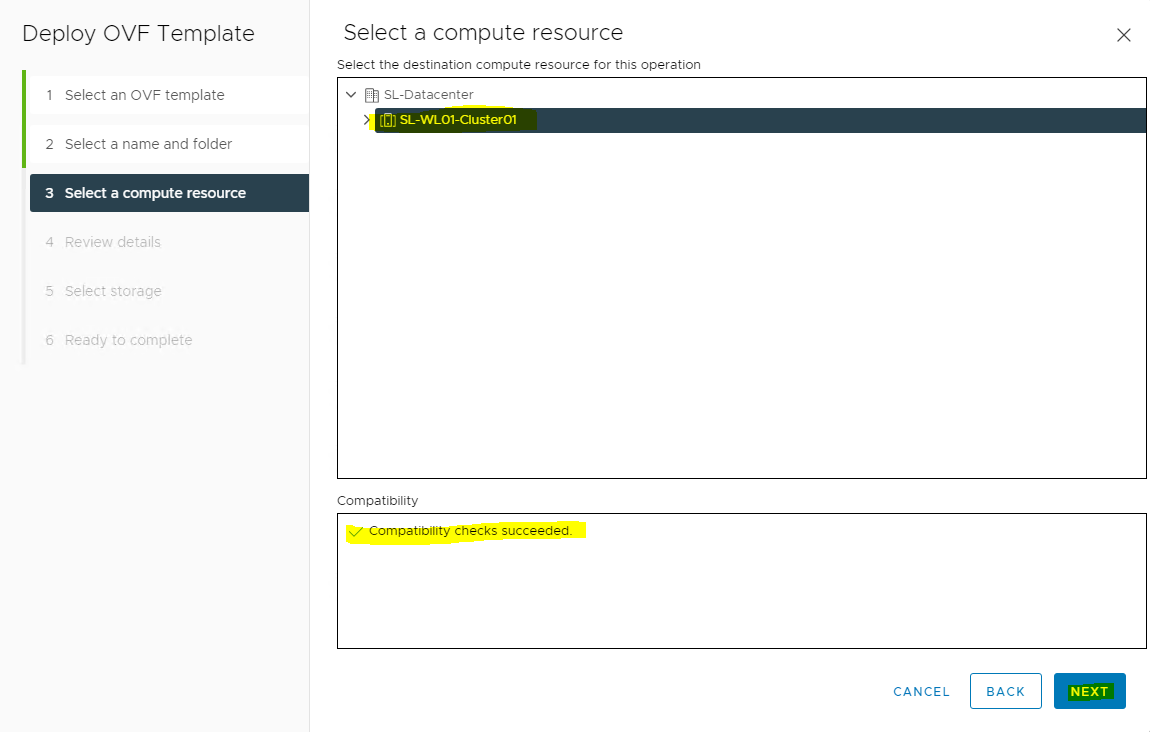
Select the compute resource where you want to place your NSX manager (i.e., the cluster, resource pool, or the host) → check compatibility has succeeded → click NEXT.
-
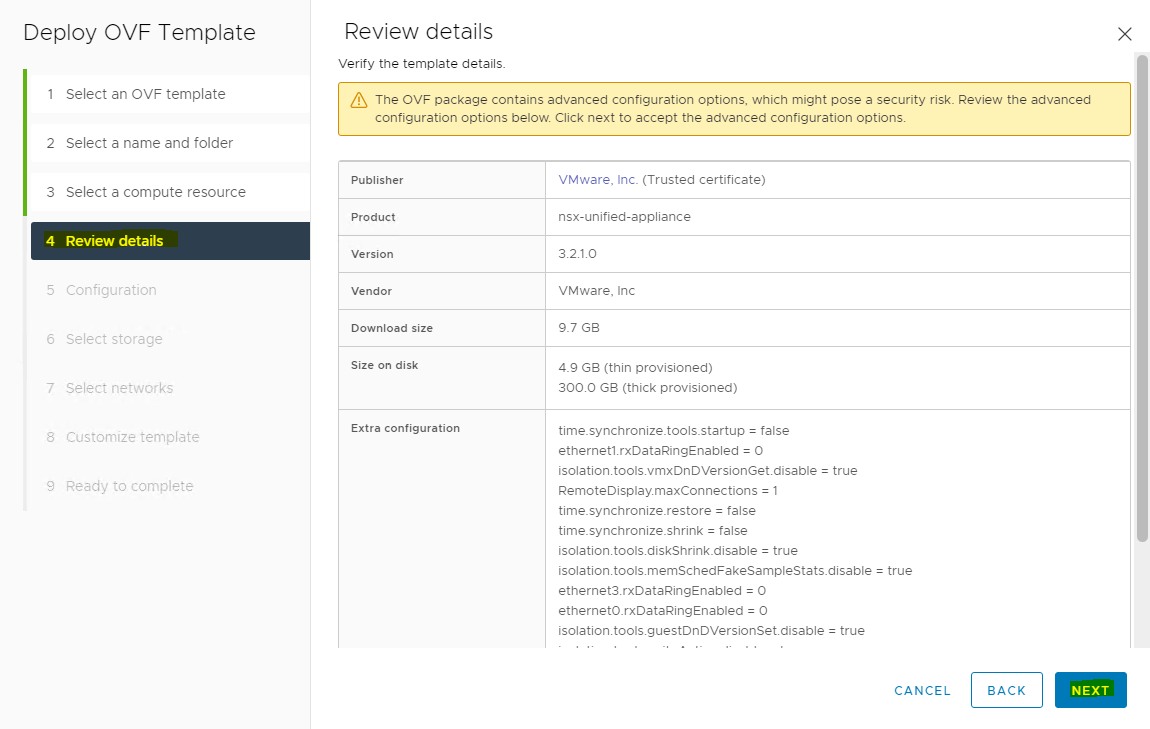
Review the details → click NEXT.
-
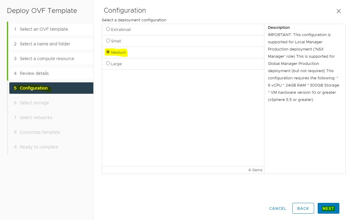
Select deployment size (Medium) → click NEXT.
When selecting "Small" as the deployment configuration, some of the services do not work. Always use "Medium" or "Large".
-
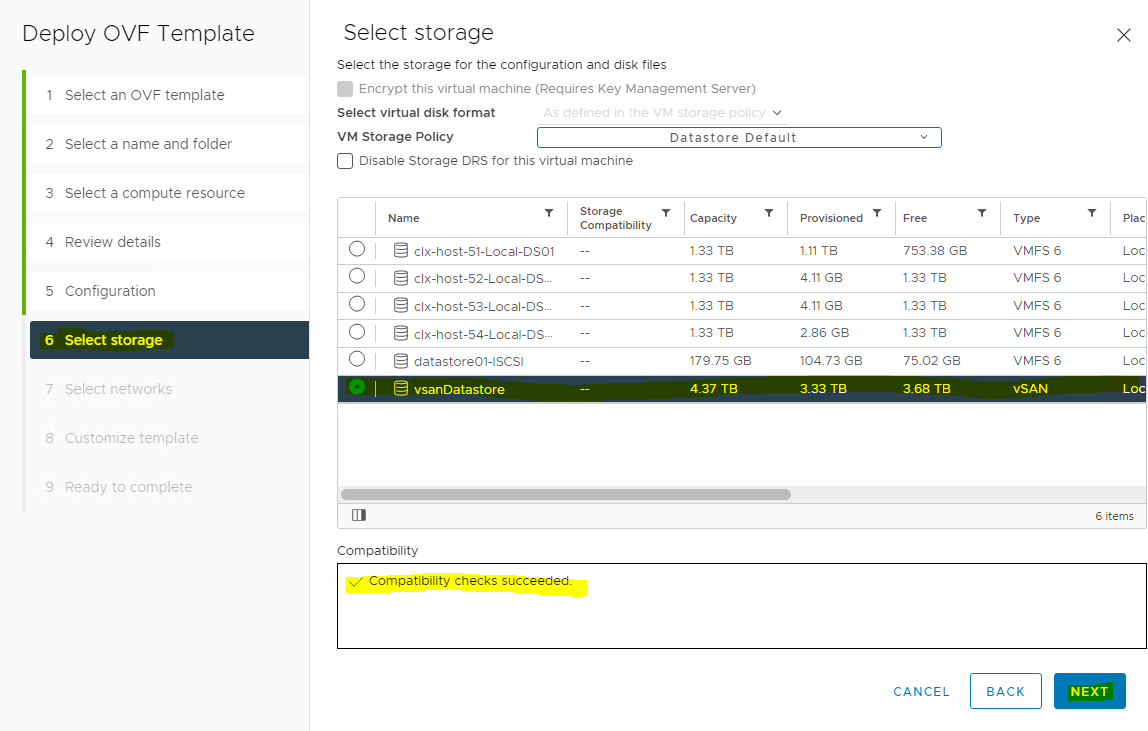
Select the Storage/datastore where NSX-T manager should be placed → click NEXT.
-
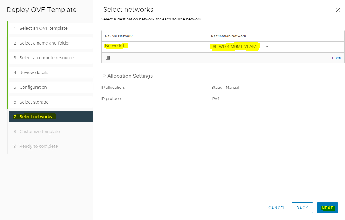
Select the Management network → click NEXT to move to the "Customize Template" screen.
-
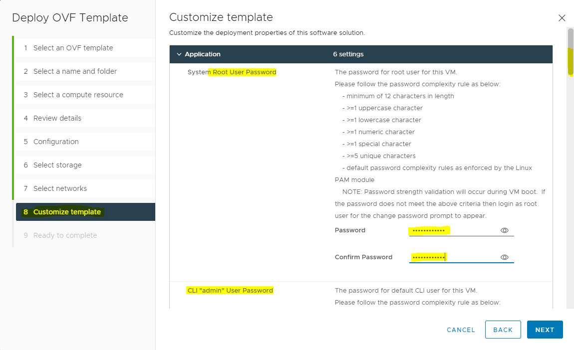
Specify the root, admin, and audit account’s password → scroll down.
Strong password is required.
-
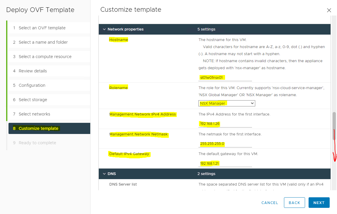
Provide the Hostname, Rolename (NSX Manager has 3 roles, as seen below), and networking details → scroll down.
-
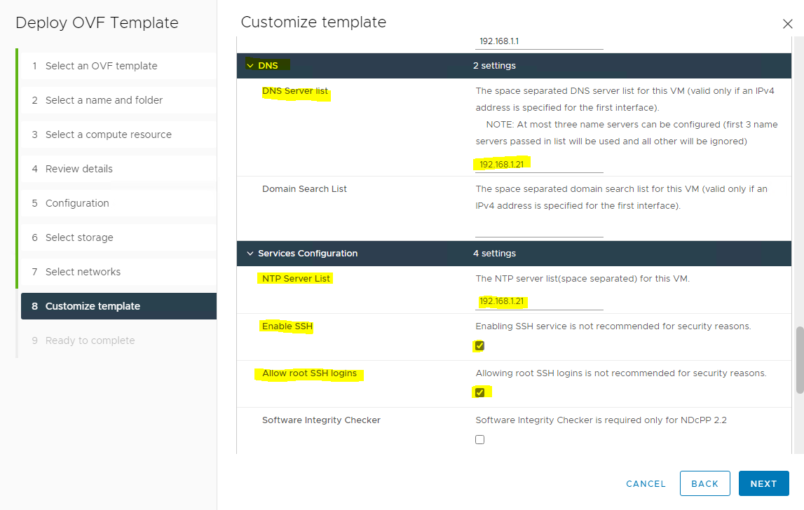
Assign the DNS and NTP details and choose whether SSH needs to be enabled on the NSX-T Manager → click NEXT.
-
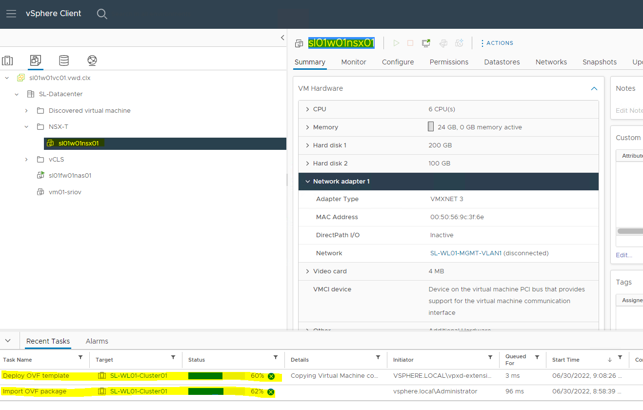
Finish the wizard. Review the details and click FINISH. Wait for the NSX manager appliance to be successfully deployed.
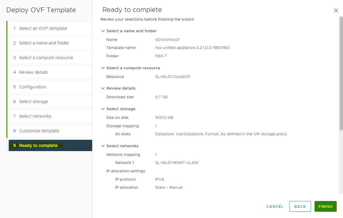
As seen below, the NSX Manager will be deployed in a maximum of 5-10 minutes.
-
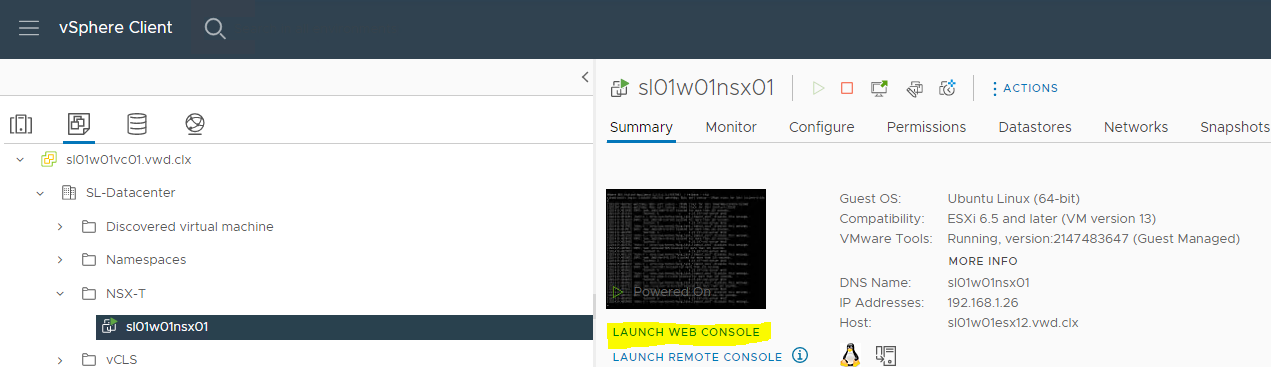
Once the appliance is successfully deployed, Power on and wait at least 15 minutes for all the services to come up.
-
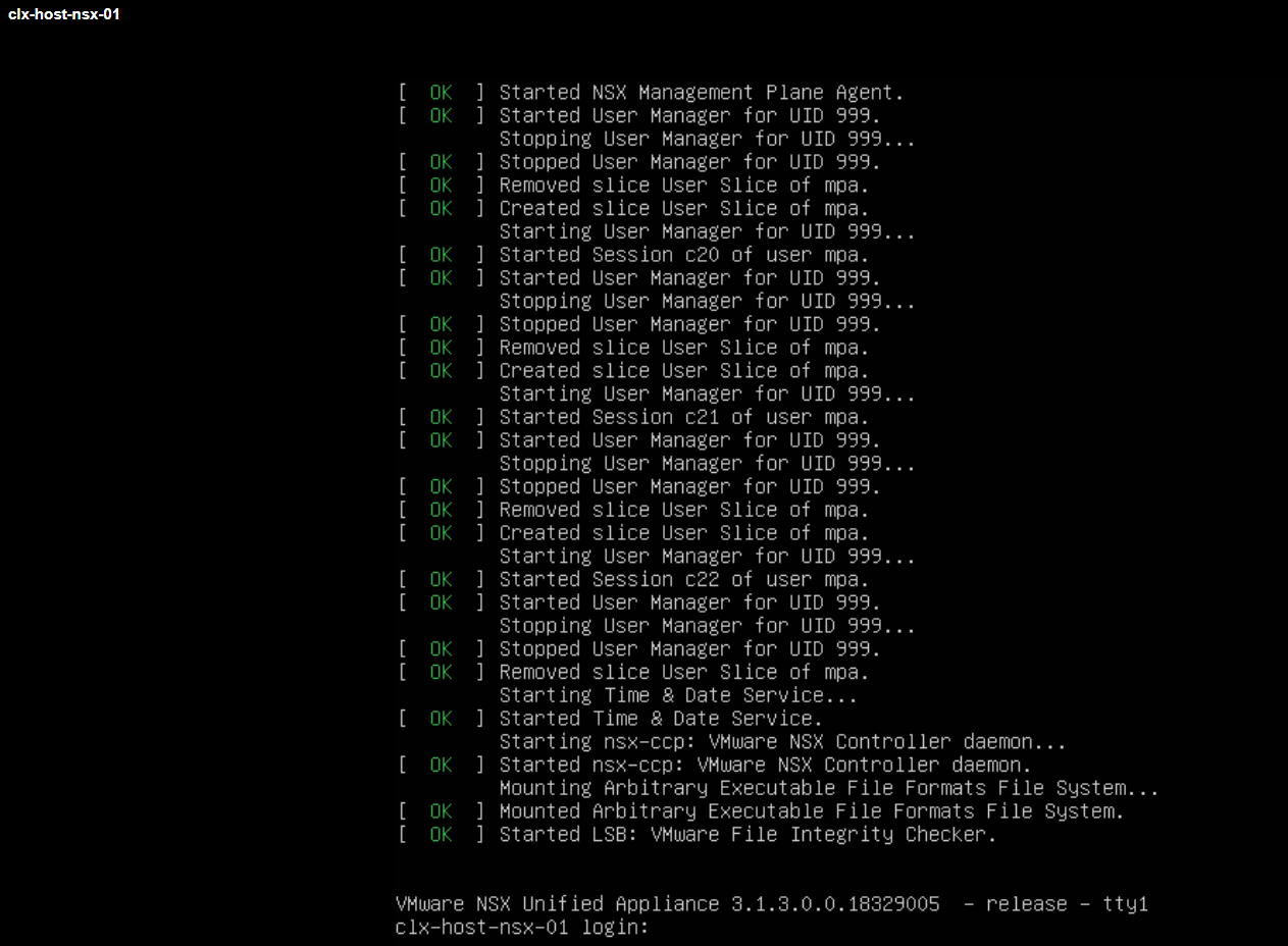
Once the services are up, a login prompt is shown. At this point, wait 10 more minutes as backend services need to start the web-portal-related services.
Post-Deployment Health Checks
Once done, do the following post-deployment steps:
-
Open the console and try to log in with admin credentials using putty. You will see the version number and the role.

-
Verify the network configuration by using the command below.
NSX-T Manager Console
get interface eth0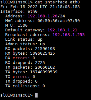
-
Check the services status by running the following command.
NSX-T Manager Console
get services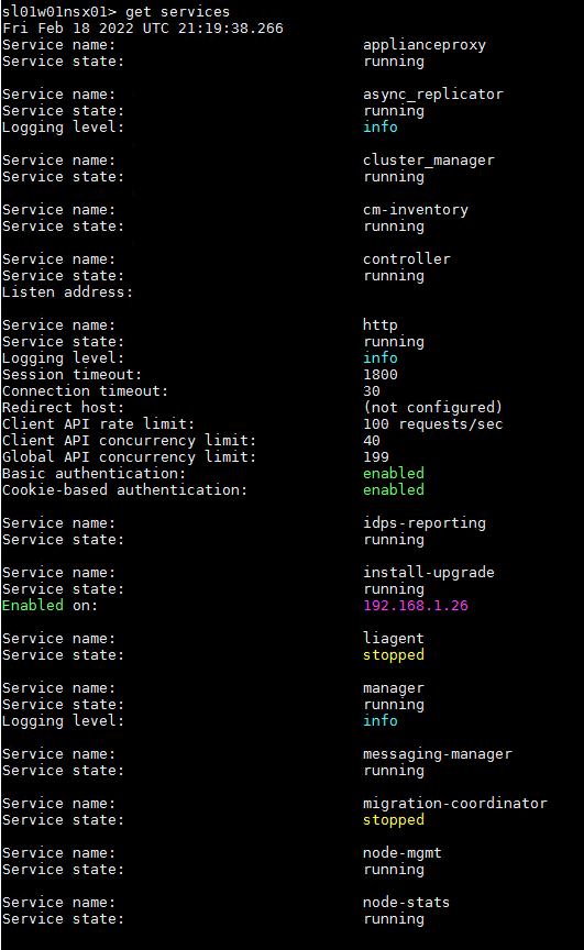
Liagent, migration-coordinator and SNMP services are not started by default.
Configuration
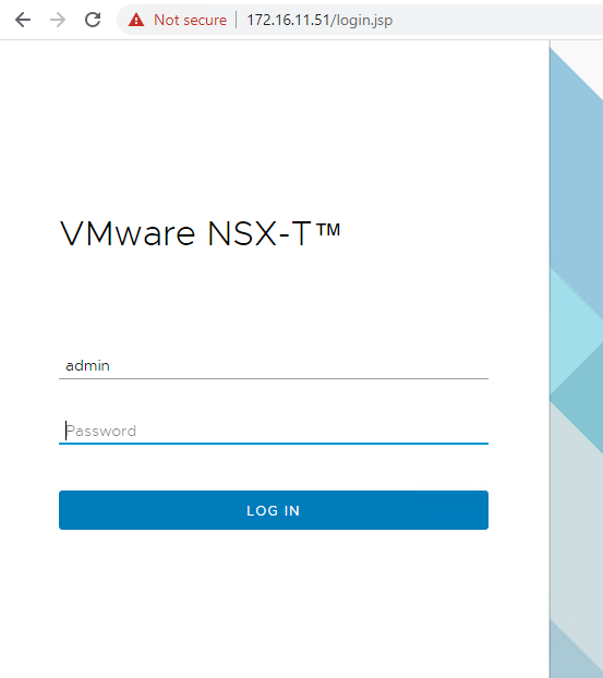
-
Log in to NSX manager UI login page by using the URL "https://<fqdn or IP>".
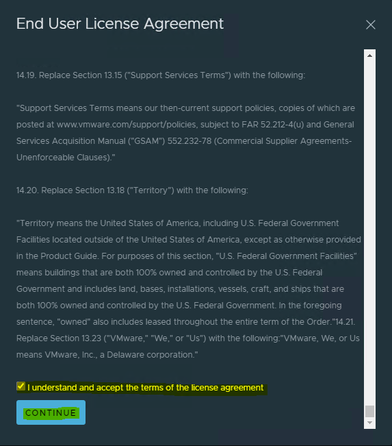
-
Accept the EULA on the first login to the NSX manager with dark theme.
-
Decide whether to join the Customer Experience Improvement Program.
.png?cb=3c4c757e4265eaa62c2430f316862227)
-
Take a quick tour, in case you need.
-
Finally, the NSX-T manager is presented.
-
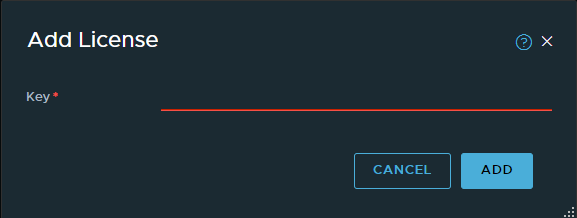
Navigate to Licenses and the NSX-T license (System → Licenses and click on +ADD LICENSE).
-
Add a license and click ADD.
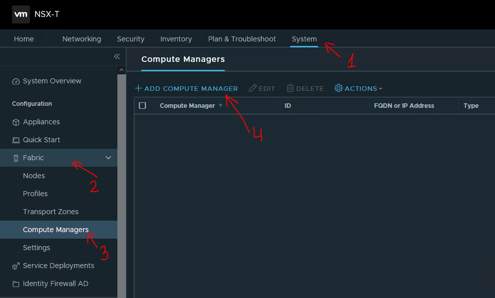
Adding a Compute Manager
-
To add a compute manager, navigate to System → Fabric → Compute Managers → click ADD COMPUTE MANAGER to add vCenter as compute manager.
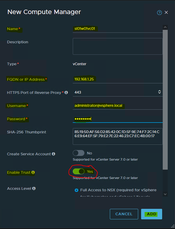
-
Fill in the vCenter details → click ADD.
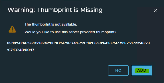
-
Click ADD, when presented with the vCenter server thumbprint window.
-
Wait for registration to complete. The status will be changed to registered and connection status to "Up".

Optional
-
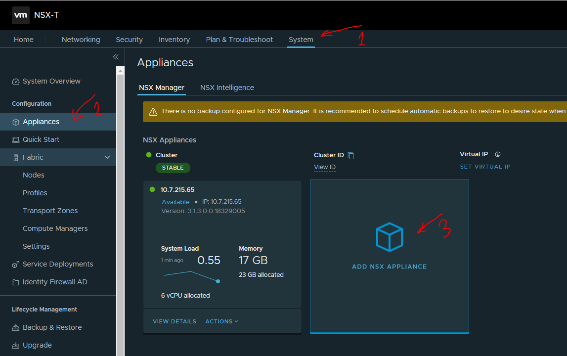
To deploy additional NSX-T manager nodes, navigate to System → Appliances → click ADD NSX APPLIANCE.
-
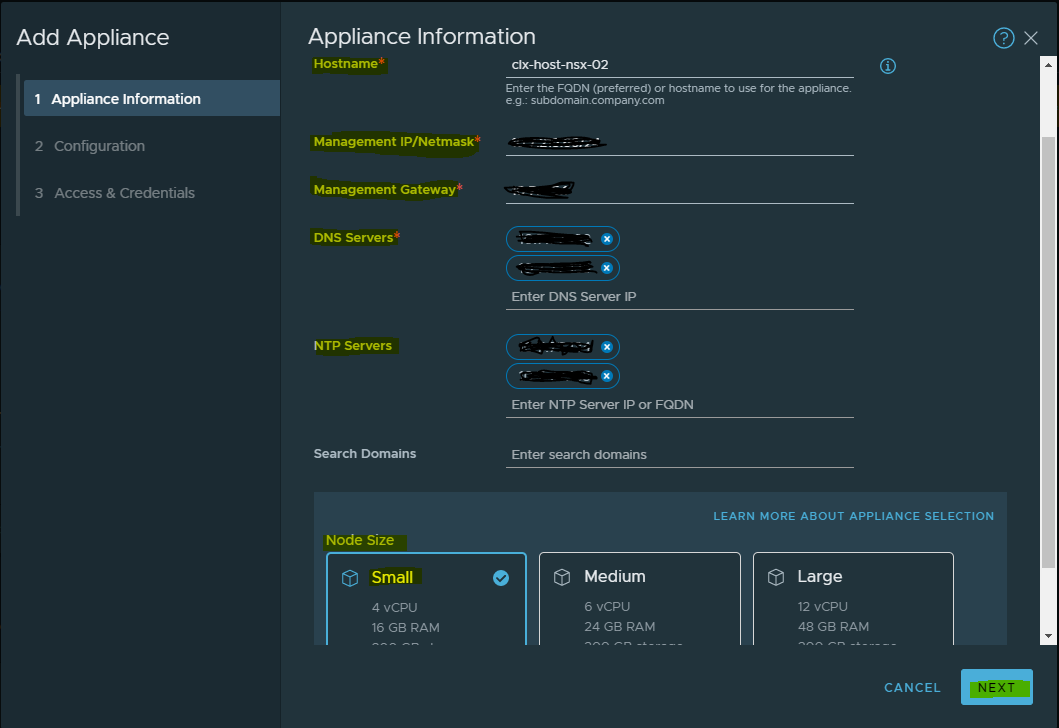
Fill in the details for the additional manager such as Hostname, Management IP/Netmask, Gateway, DNS, or NTP and select the Node Size of the manager (should be identical to first manager) → click NEXT.
-
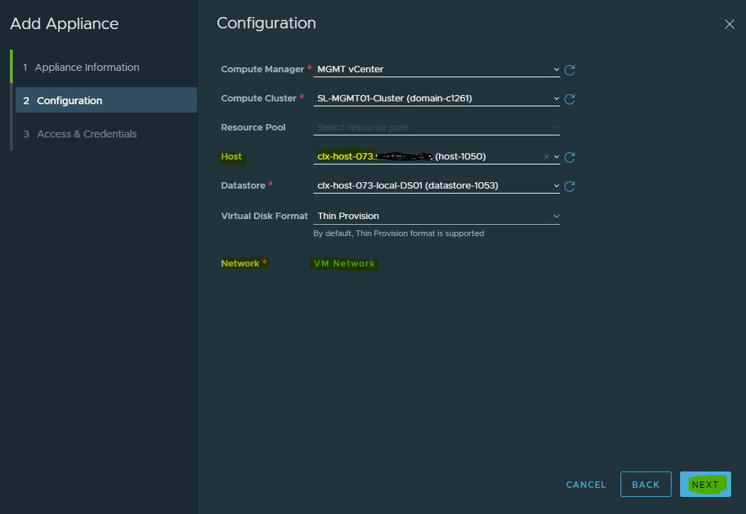
Select the appliance placement configuration → click NEXT.
-
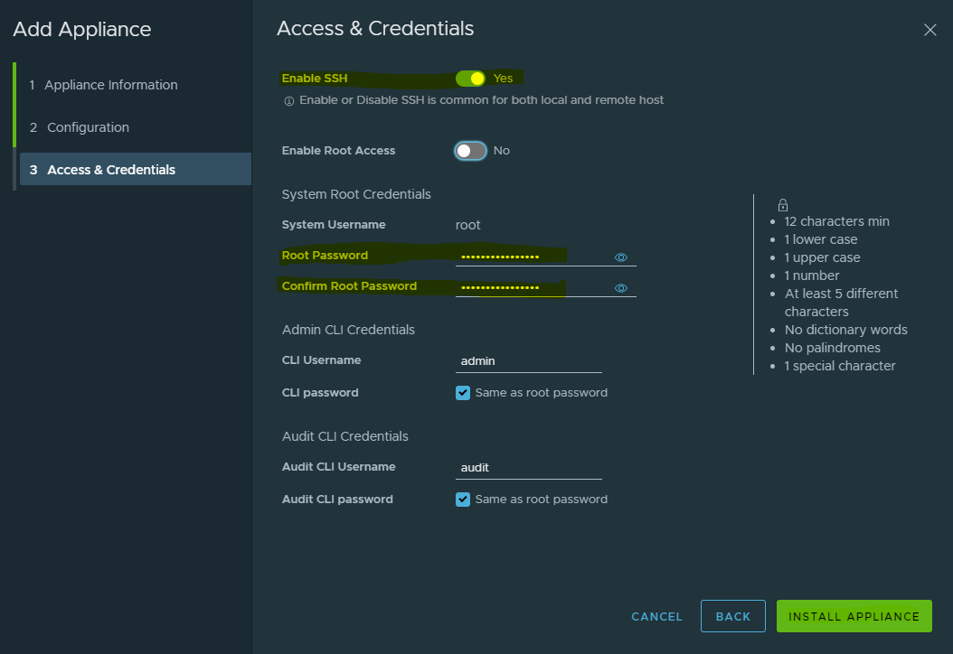
Complete NSX manager passwords for access (use the same password as in the first manager) and enable SSH access → click on INSTALL APPLIANCE.
-
Repeat same steps for deploying third NSX-T manager node, wait for both the nodes to be deployed and joined cluster.
-
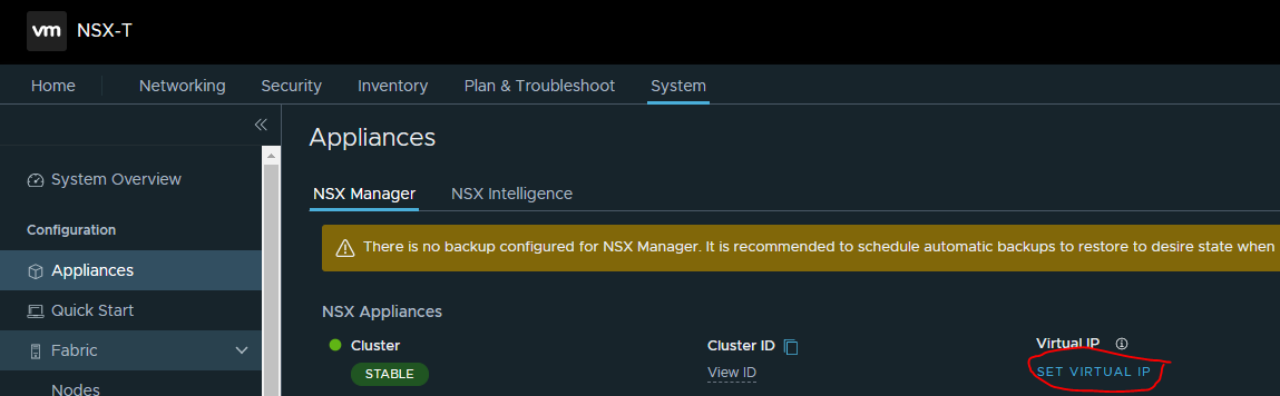
Assign the cluster VIP for ease of management. Be sure that cluster IP does not do load balancing and only provides ease of management.
The deployment of NSX-T manager and controller cluster is complete.
NSX-T Configuration
Network administrators must prepare the network with the supported NIC cards and drivers before creating VDS enabled transport zone.
Uplink Profiles
An uplink profile defines the policies for links from a hypervisor hosts to the NSX-T logical switches or from NSX Edge nodes to top-of-rack switches. The settings defined by these profiles may include teaming policies, active/standby links, transport VLAN ID, and MTU settings.
Uplink profiles enables consistent configuration of identical capabilities for network adapters across multiple hosts and nodes. By default, there are two uplink profiles that are provided with NSX-T and cannot be edited, that's why new profiles for the Edge uplink should be created (for hosts’ uplinks as well).
See Create an Uplink Profile, for more detailed information.
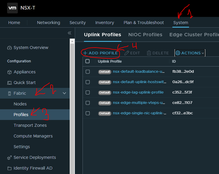
Create Host Uplink Profile
To create a Host uplink profile in NSX-T Manager, do the following:
-
Navigate to System → Fabric → Profiles → Uplink Profiles → +ADD.
-
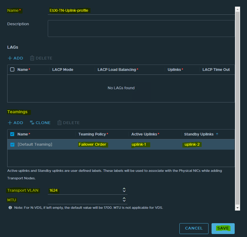
Assign a name to the profile and fill the description.
-
Under "Teamings", set the Teaming Policy to "Failover Order".
-
Set the Active Uplinks to uplink-1 and the Standby Uplinks to uplink-2.
The Transport VLAN will be an Overlay VLAN ID (in the example provided, 1624) since these uplinks are connected directly to the hosts and need to be tagged accordingly.
The default MTU is set to 1600. You can set it to a higher value which is supported by your Jumbo Frames configuration and then click ADD.
MTU not fill.
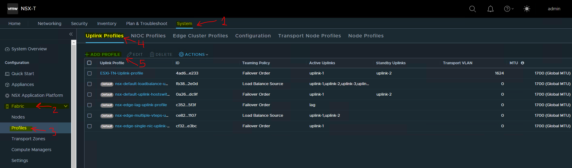
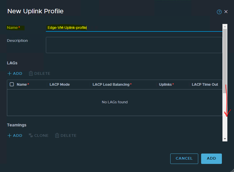
Create Uplink Profile for Edge VMs Transport Nodes.
To create a Host uplink profile in NSX-T Manager, do the following:
-
Navigate to System → Fabric → Profiles → Uplink Profiles → +ADD.
-
Assign a name to the profile and fill the description.
-
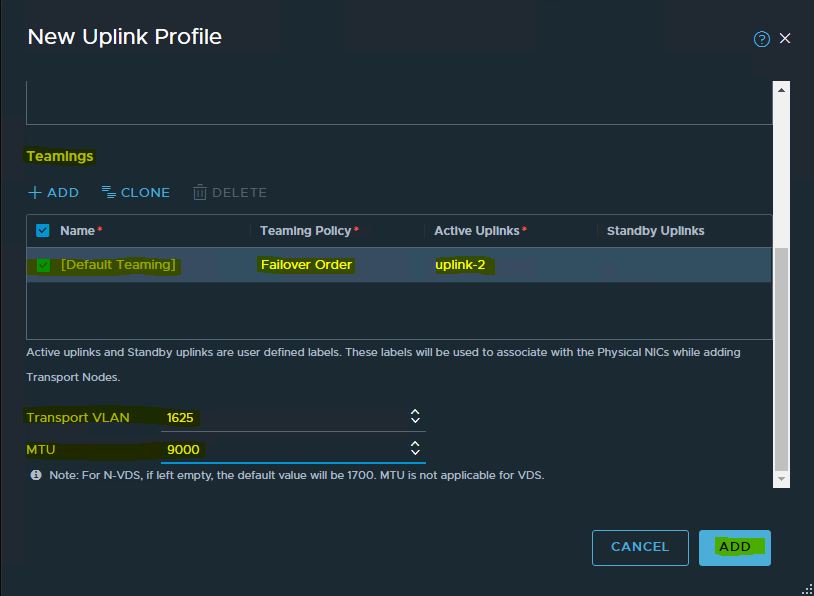
Under "Teamings", set the Teaming Policy to "Failover Order".
-
Set the Active Uplinks to uplink-2.
-
The Transport VLAN will be an Overlay VLAN ID (in the example provided, 1625) since these uplinks are connected directly to the hosts and need to be tagged accordingly.
The default MTU is set to 1600. You can set it to a higher value which is supported by your Jumbo Frames configuration and then click ADD.
In this setup, we will set the MTU to 9000.
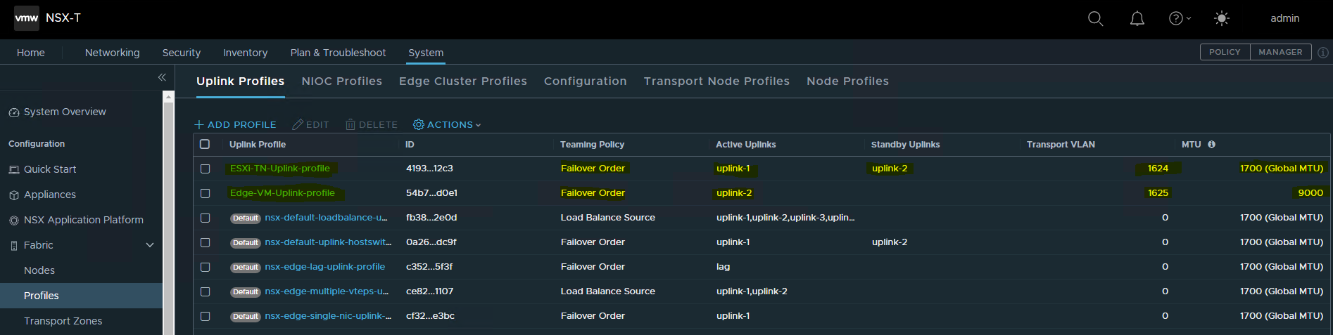
It will look like the following with the 2 new uplink profiles being created successfully.
Transport Zones
Transport Zones dictate which hosts (and consequently which VMs) can participate in the use of a particular network. There are two types of transport zones: an overlay and a VLAN.
-
The overlay transport zone is used by both host transport nodes and NSX Edges and is responsible for communication over the overlay network.
-
The VLAN transport zone is used by the NSX Edge for its VLAN uplinks.
Both types create an N-VDS on the host or Edge to allow for virtual-to-physical packet flow by binding logical router uplinks and downlinks to physical NICs. For more information, please see the Transport Zones and Profiles.
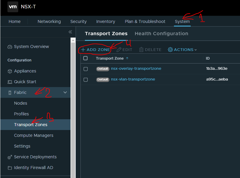
Create Transport Zone
To create a Transport Zone in the NSX-T Manager, navigate to System → Fabric → Transport Zones → +ADD.
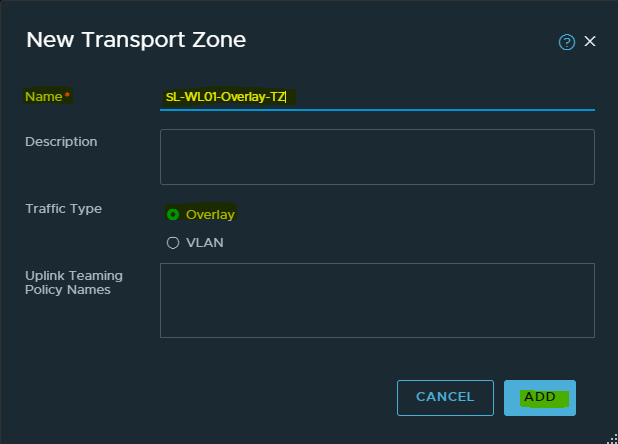
Transport Zone with Overlay Traffic Type
Provide a Name and select the Traffic Type as Overlay (Geneve) and then click ADD.
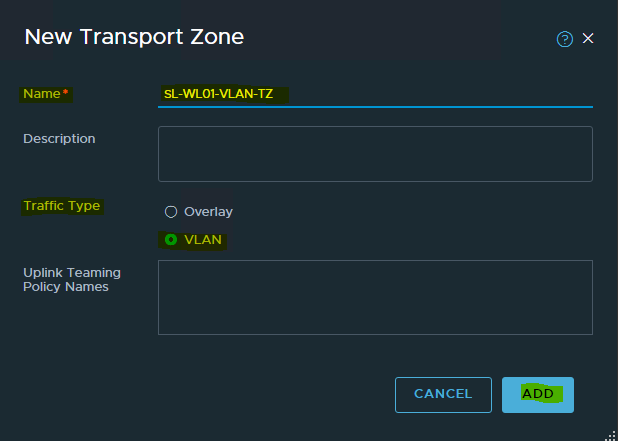
Transport Zone with VLAN Traffic Type
Provide a Name and select the Traffic Type as VLAN and then click ADD.
Create NSX-T TEPs IP Pools
Each transport node (i.e., hypervisors) is assigned with an IP address for the TEP interface. DHCP, Static IP List, and IP address Pool can all be used for assigning IP addresses for the TEP (Tunnel Endpoint) interfaces.
To configure the ESXi hosts as Transport nodes, NSX-T IP Pool will be created to assign IP addresses for the TEP interfaces.
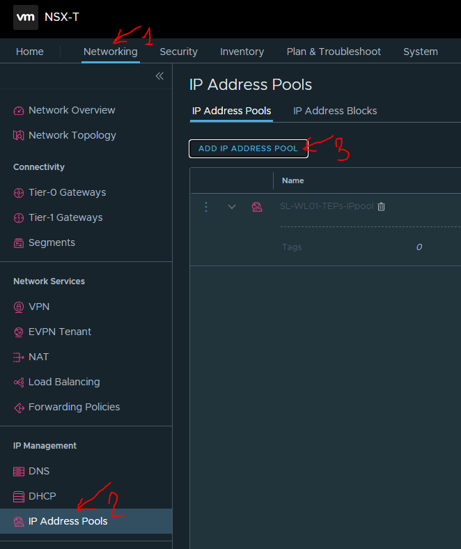
To create an IP Pool, in the NSX-T Manager, do the following"
-
Navigate to Networking → IP Address Pools → ADD IP ADDRESS POOL.
-
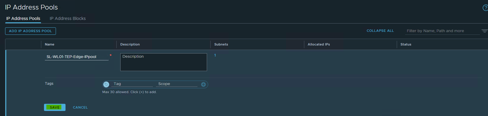
Specify the name and description of the IP address pool → click Set.
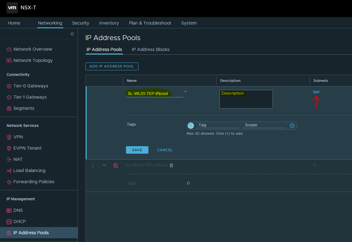
-
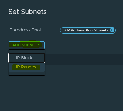
Click ADD SUBNET → select IP Ranges.
-
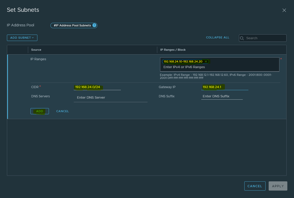
Specify the IP Address Ranges, along with CIDR and Gateway IP, address for the specified IP ranges → click ADD.
-
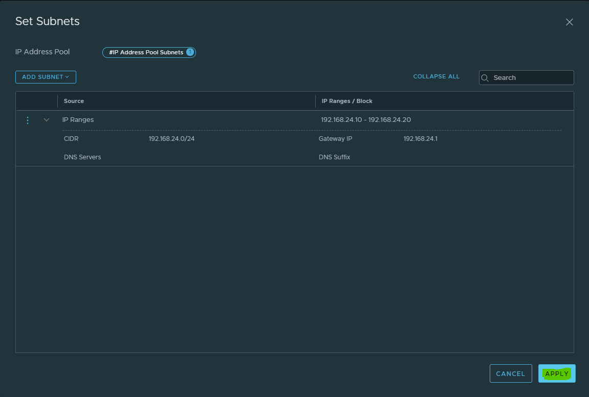
Click Apply.
-
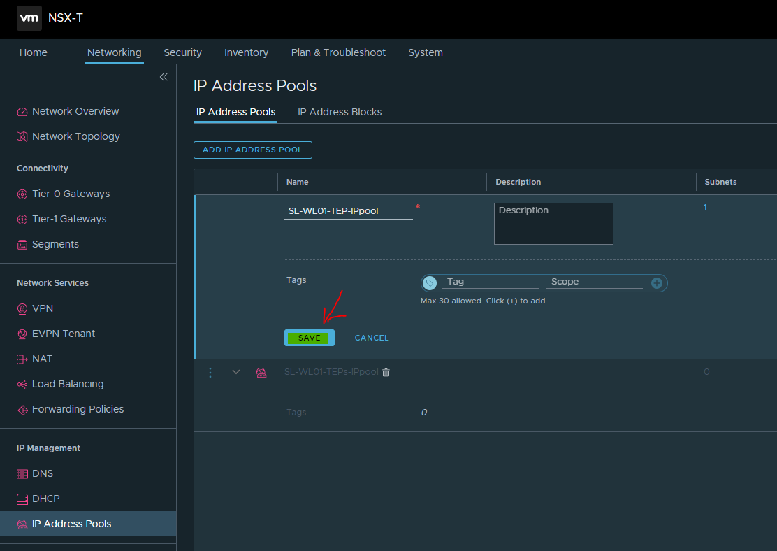
Click SAVE to create the IP Pool.
-
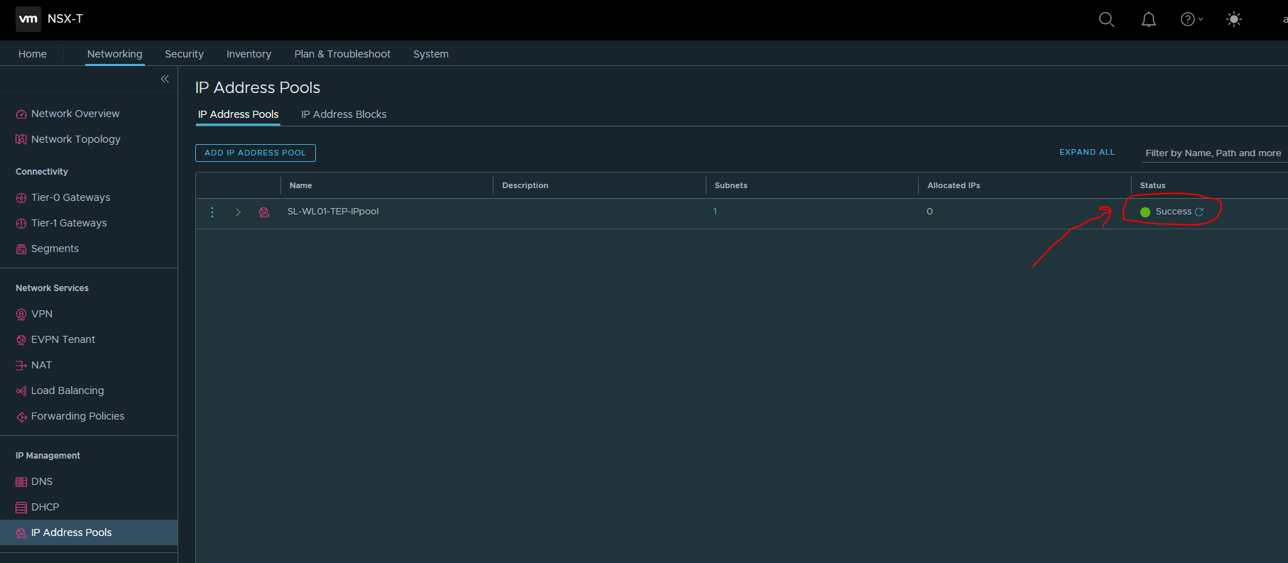
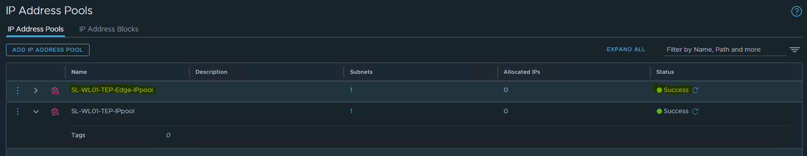
Once the IP Pool is created, the status will be changed to Success.
Create NSX-T Edge VM TEPs IP Pools
Each NSX Edge VM is assigned with an IP address for the TEP interface. DHCP, Static IP List, and IP address Pool can all be used for assigning IP addresses for the TEP (Tunnel Endpoint) interfaces.
To configure the ESXi hosts as Transport nodes, NSX-T IP Pool will be created to assign IP addresses for the Edge VM TEP interfaces.
To create an IP Pool, in the NSX-T Manager, do the following"
-
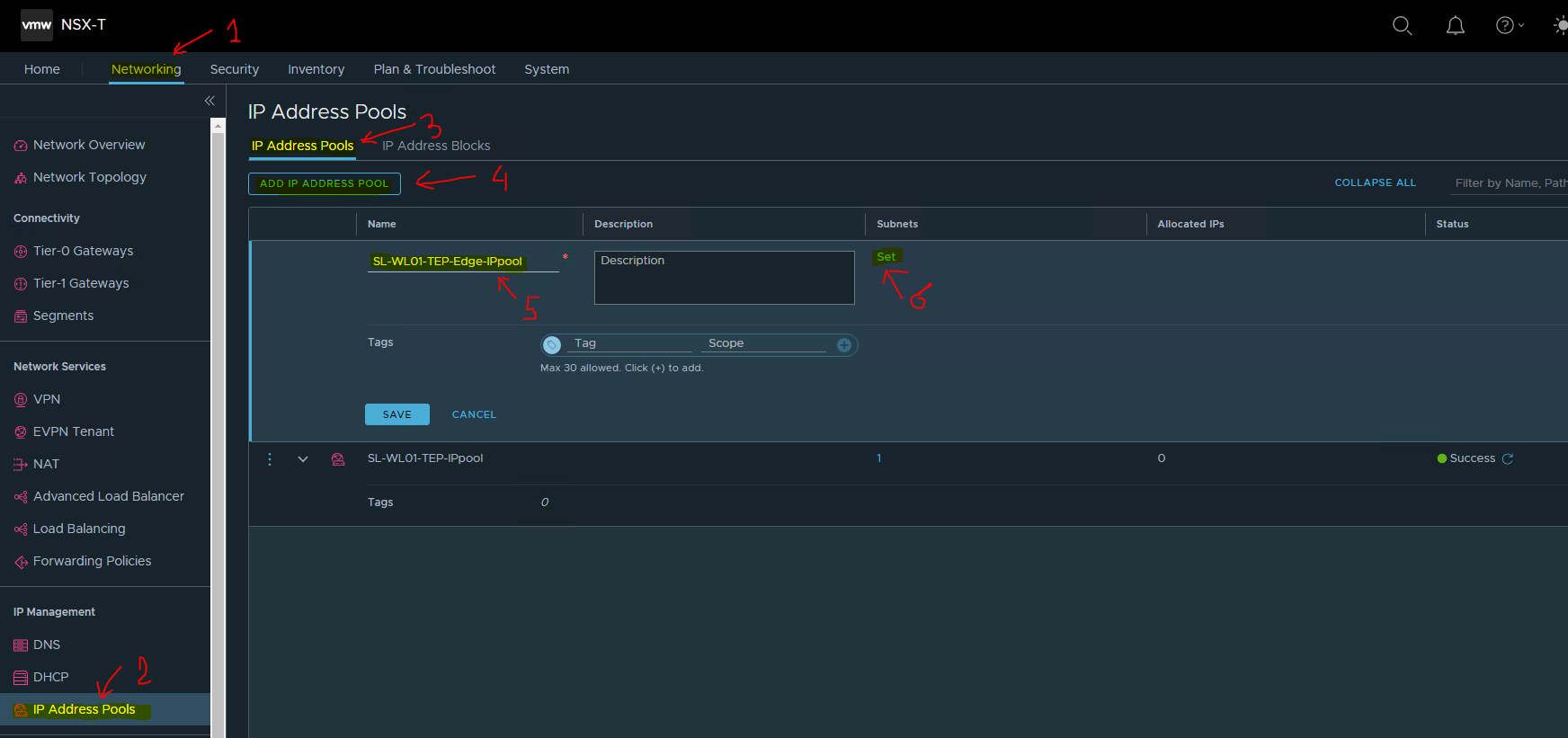
Navigate to Networking → IP Address Pools → ADD IP ADDRESS POOL.
-
Specify the name and description of the IP address pool → click Set.
-
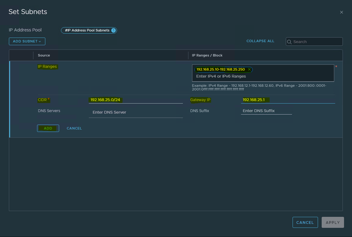
Click ADD SUBNET → select IP Ranges.
-
Specify the IP Address Ranges, along with CIDR and Gateway IP, address for the specified IP ranges → click ADD.
-
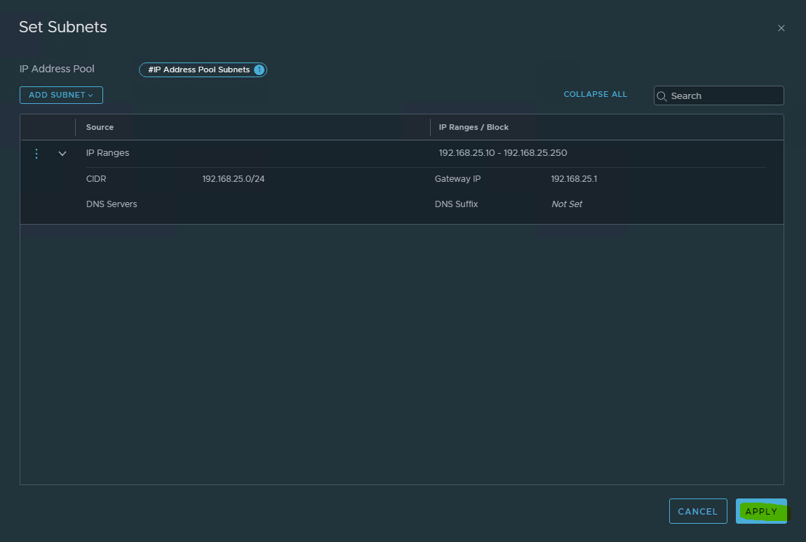
Click Apply.
-
Click SAVE to create the IP Pool.
-
Once the IP Pool is created, the status will be changed to Success.
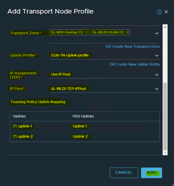
Create Transport Nodes Profiles for ESXi Hosts.
To create Transport Nodes Profile.
-
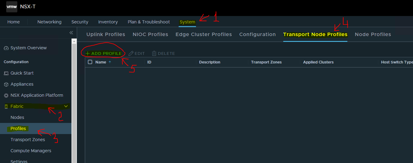
Navigate to System → Fabric → Profiles → Transport Node Profiles → click Add.
-
In the opened window:
-
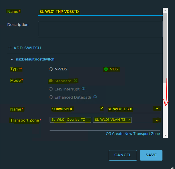
Specify the Name → SL-WL01-TNP-VDSSTD and description of the Transport Nodes Profile.
-
Select Type → VDS.
-
Select Mode → Standard.
-
Select Names of vCenter → sl01wl01vc01 and VDS → SL-WL01-DS01.
-
Select Transport Zones were created before → SL-WL01-Overlay-TZ and SL-WL01-VLAN-TZ.
-
Scroll down.
-
Select the Uplink Profile → ESXi-TN-Uplink-profile.
-
Select the IP Assignment (TEP) → Use IP Pool.
-
Select the IP Pool → SL-WL01-TEP-IPpool.
-
In Team Policy Uplink Mapping Select uplink-1 → Uplink 1 and uplink-2 → Uplink 2.
-
Click Add.
-
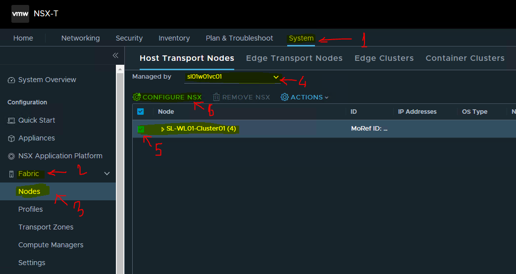
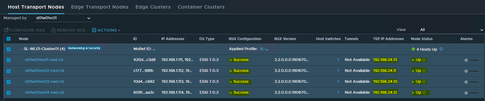
Enabling ESXi as NSX Transport Nodes
To enable ESXi as NSX Transport Nodes.
-
Navigate to System → Fabric → Nodes → Host Transport Nodes
-
Select Managed by → sl01wl01vc01.
-
Select SL-WL01-Cluster01(4)
-
Click Configure NSX.
-
In a open window select the Transport Nodes Profile Name we created → SL-WL01-TNP-VDSSTD and click Apply.
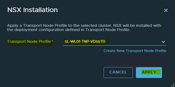
You can see the installation is progressing.
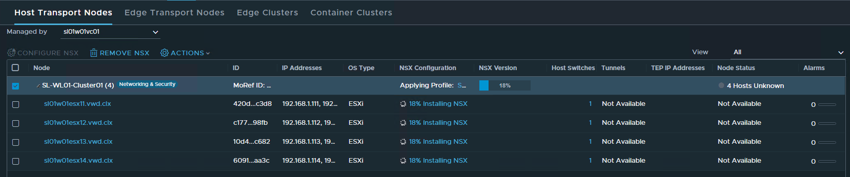
Wait to the following the hosts are successfully installed with NSX.
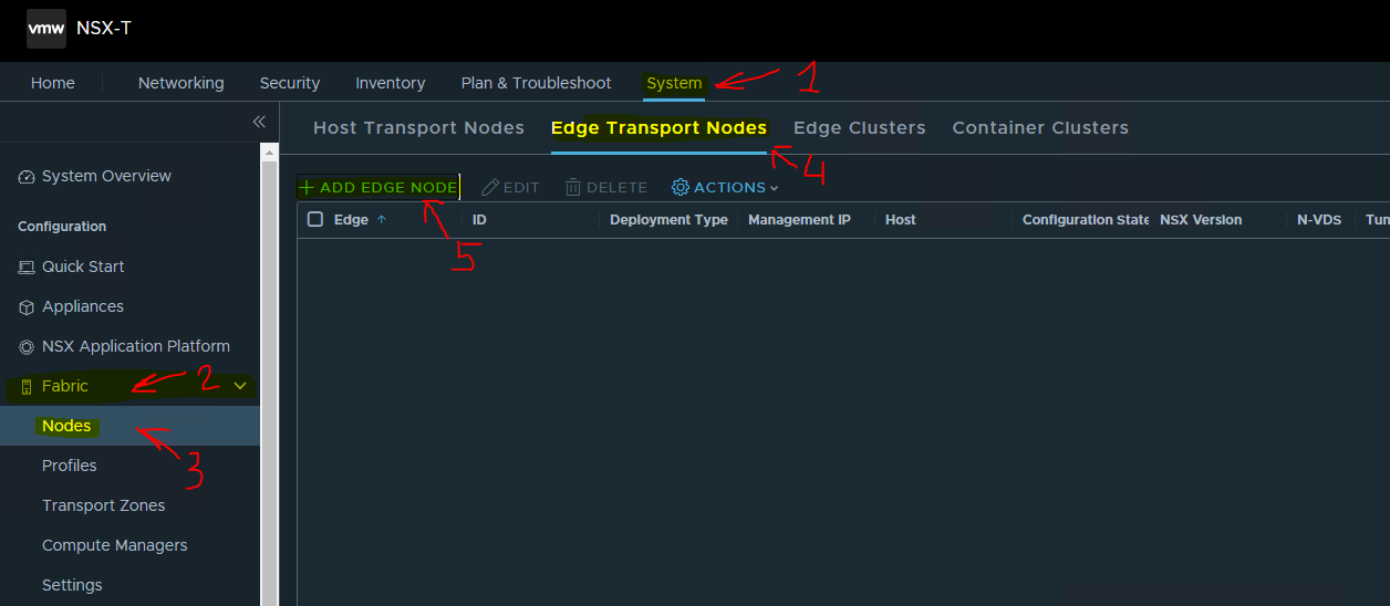
Deploy Edges
To deploy Edges.
-
Navigate to System -> Fabric -> Nodes -> Edge Transport Nodes. Click ADD EDGE VM.
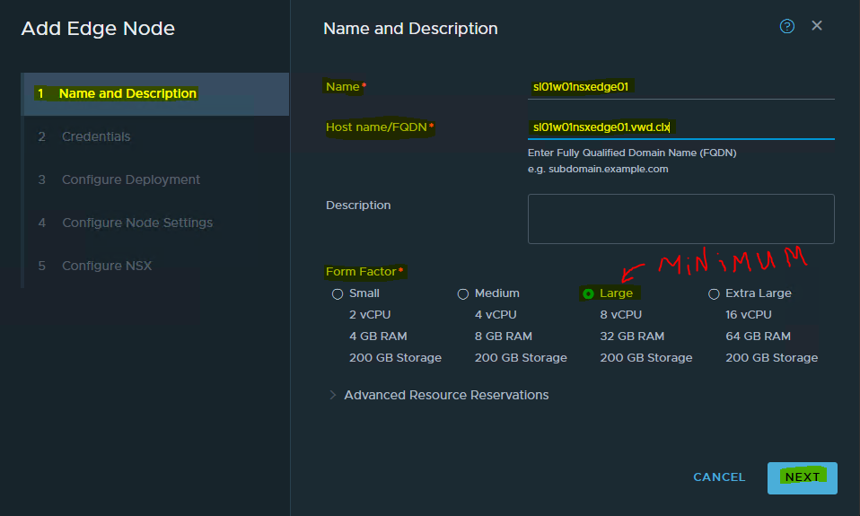
-
In the opened window fill in the Name → sl01wl01nsxedge01, Host name/FQDN → sl01wl01nsxedge01.vwd.clx and choose the size.
For vSphere with Kubernetes, you will need to deploy a minimum of Large Edge VM appliance.
Click on NEXT.
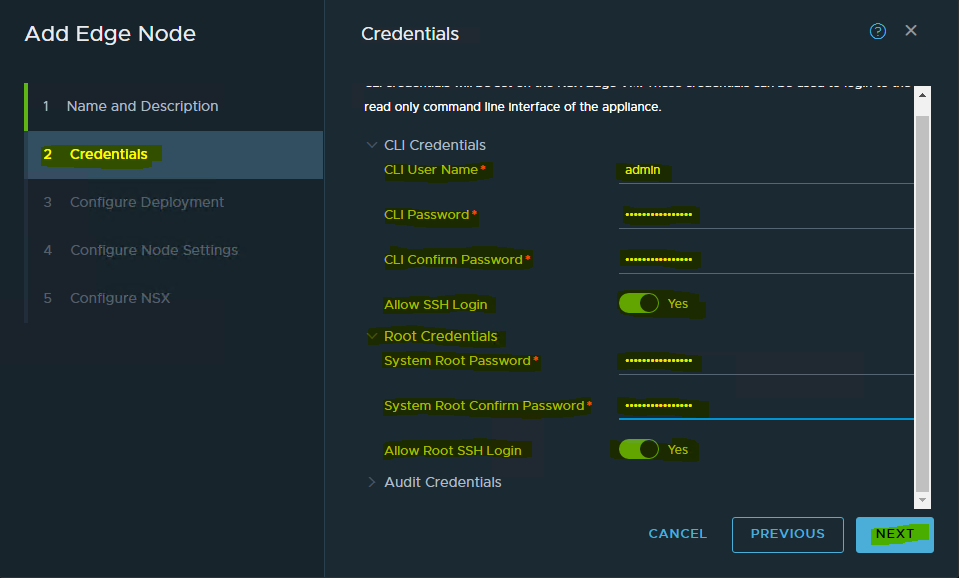
-
Fill in the credentials. Click NEXT.
-
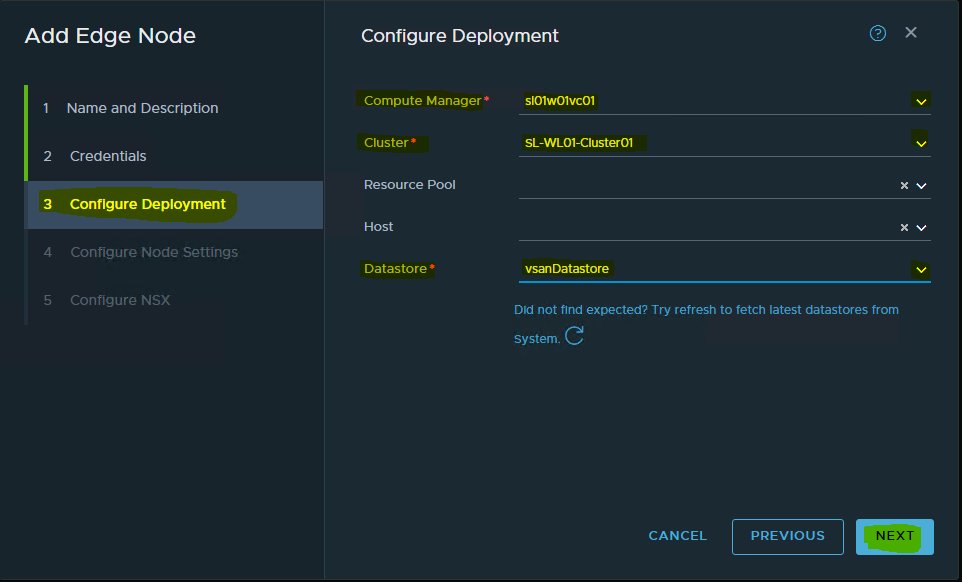
Select the Compute Manager -> sl01wl01vc01, Cluster-> SL-WL01-Cluster01 and Datastore-> vsanDatastore.
-
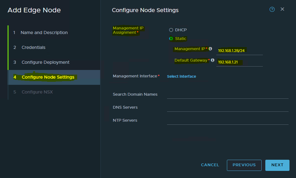
Configure the Management IP -> 192.168.1.28/24 and Default Gateway -> 192.168.1.21.
-
Select the Management Interface by click Select Interface.
-
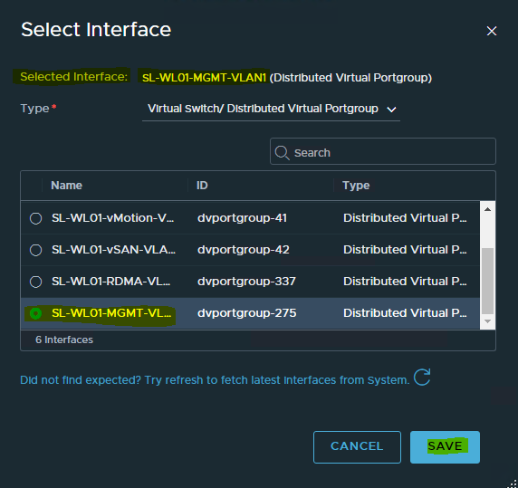
Choose the Portgroup for the Management Interface → SL-WL01-MGMT-VLAN1.
-
Click SAVE.
-
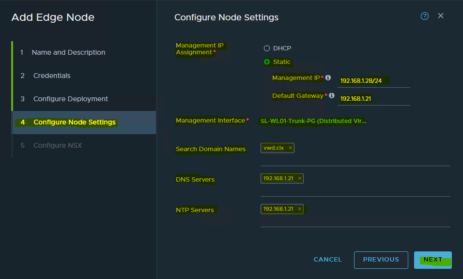
Specify Search Domain Names, DNS Servers and NTP Servers.
-
Click NEXT.
-
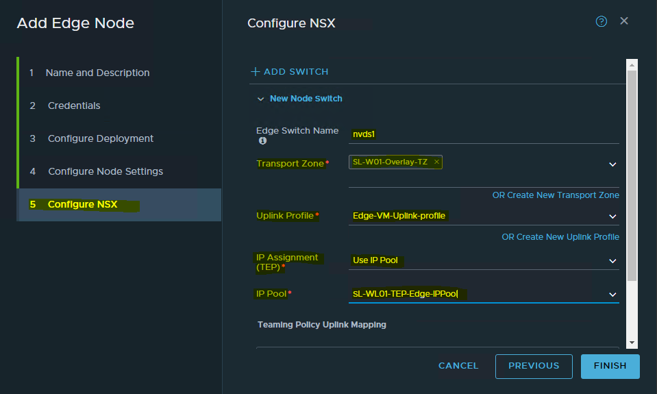
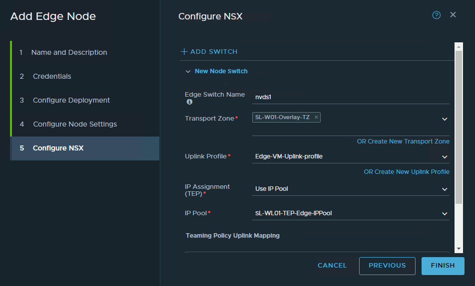
Specify the Edge Switch Name → nvds1, select the Transport Zone → SL-WL01-Overlay-TZ , Uplink Profile → Edge-VM-Uplink-profile.
Scroll Down.
We are keeping the naming convention of nvds1 for Overlay Transport Zone and nvds2 for VLAN Transport Zone.
-
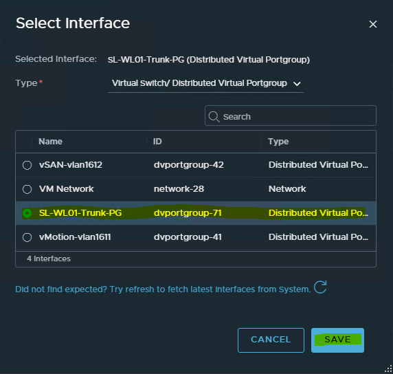
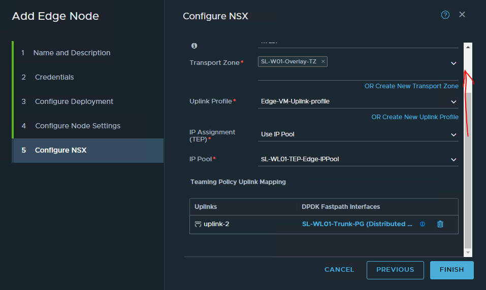
In Team Policy Uplink Mapping uplink-2 click Select Interface.
Select the VDS Portgroup – SL-WL01-Trunk-PG which we created before. -
Click SAVE.
It will look like the following with all the required fields being selected and filled out.
-
Add another switch by clicking on ADD SWITCH. **You might need to scroll up to the page to see the button.
-
Again, specify Edge Switch Name → nvds2, select the Transport Zone → SL-WL01-VLAN-TZ , Uplink Profile → Edge-VM-Uplink-profile, for the TEPs for the Edge VM.
In Team Policy Uplink Mapping uplink-2 click on Select Interface. Select the VDS Portgroup – SL-WL01-Trunk-PG which we created before.
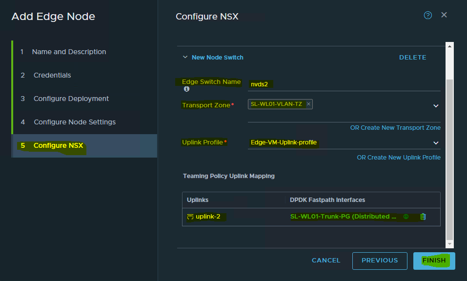
-
Click FINISH.
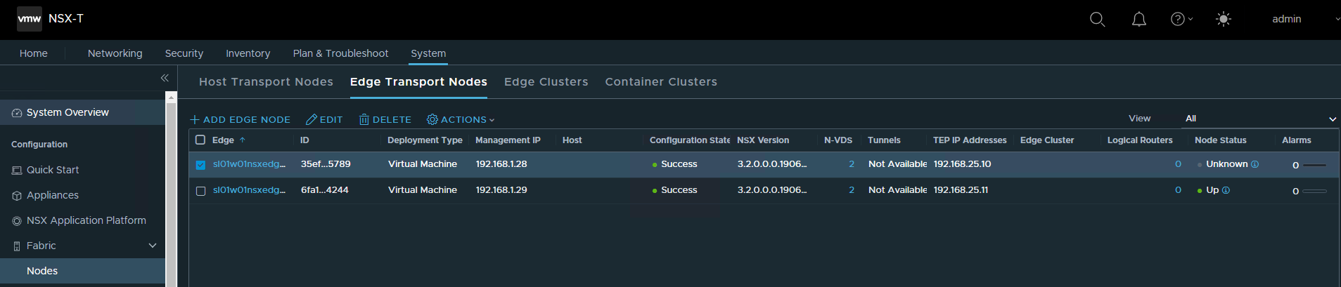
Repeat the above steps for Edge VM02 with Name → sl01wl01nsxedge02, Host name/FQDN → sl01wl01nsxedge02.vwd.clx and Management IP -> 192.168.1.29/24
It will look like the following once both the Edge VMs are deployed successfully. The installation can take several minutes.
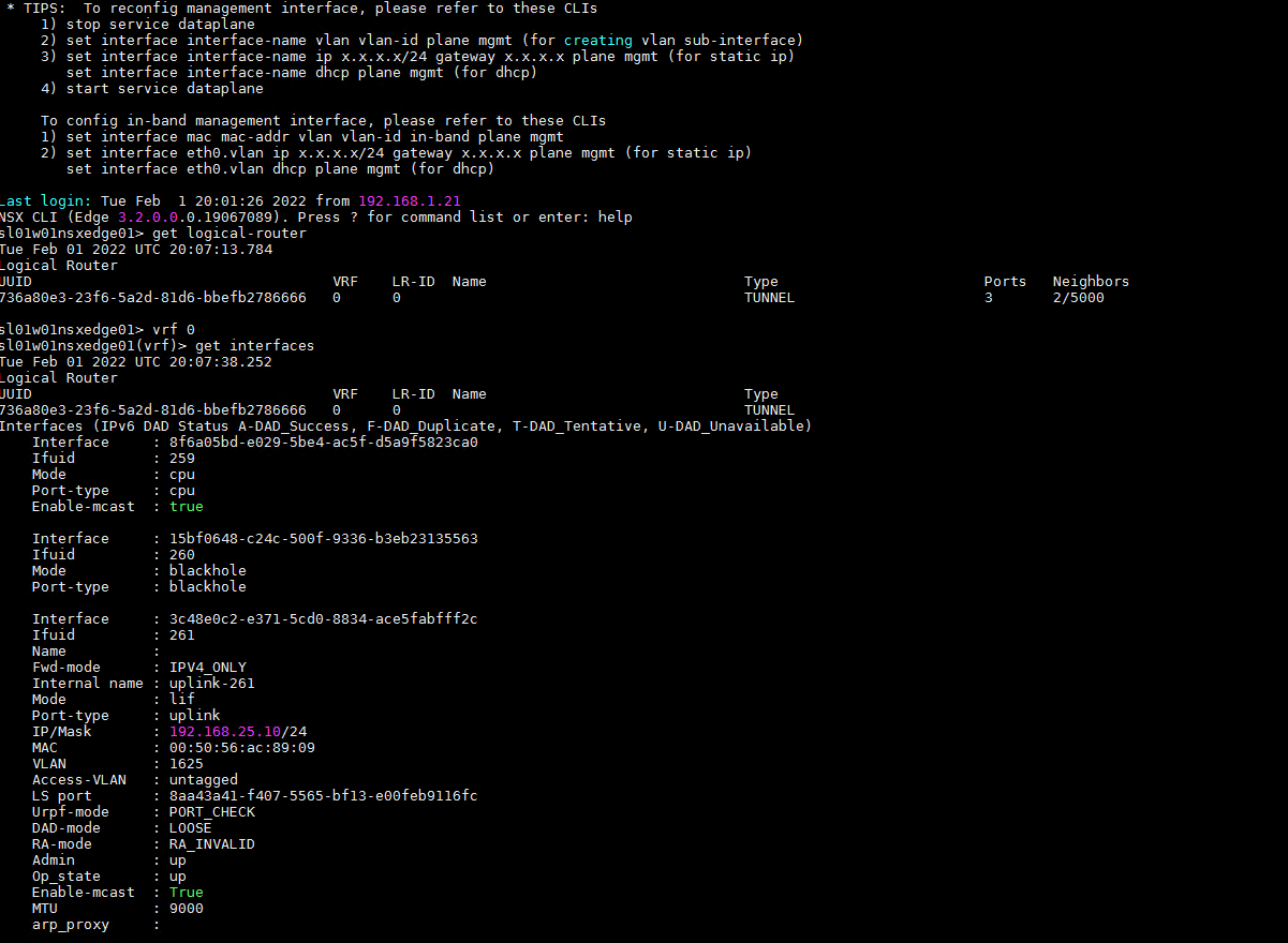
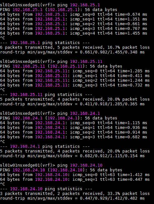
Testing Edge VMs
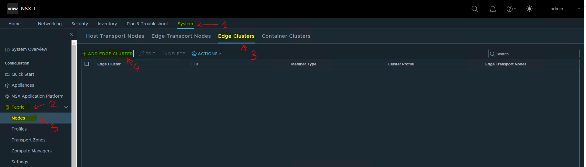
Configure the Edge Cluster
To configure the Edge Cluster.
-
Navigate to System → Fabric → Nodes → Host Transport Nodes.
-
Click ADD EDGE CLUSTER.
-
Fill the Edge Cluster Name → EdgeCluster1. Select the Edge Cluster Profile.
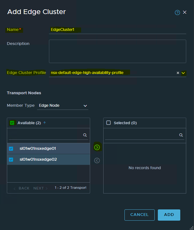
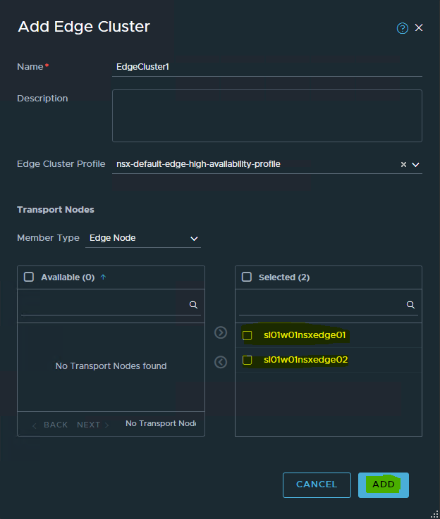
-
Select the two edge nodes that we just created in the previous step.
The following shows the Edge Cluster → EdgeCluster1 has been successfully created.
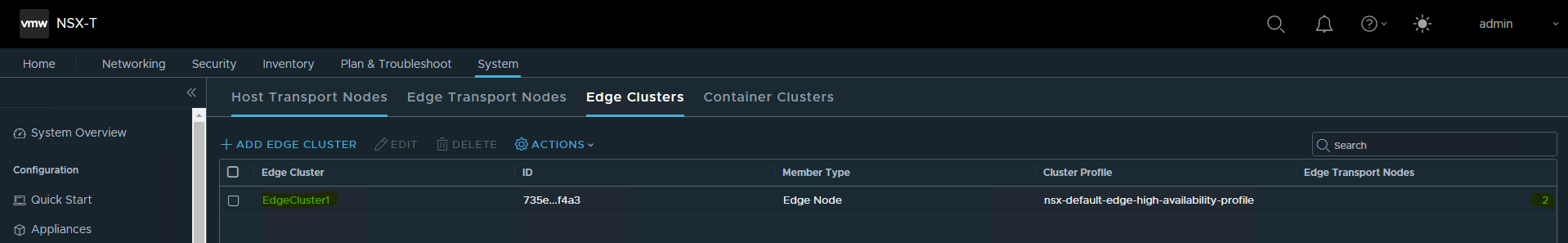
Done !
Authors
|
|
Boris Kovalev
Boris Kovalev has worked for the past several years as a Solutions Architect, focusing on NVIDIA Networking/Mellanox technology, and is responsible for complex machine learning, Big Data and advanced VMware-based cloud research and design. Boris previously spent more than 20 years as a senior consultant and solutions architect at multiple companies, most recently at VMware. He has written multiple reference designs covering VMware, machine learning, Kubernetes, and container solutions which are available at the NVIDIA Documents website. |

Last updated: