

Created on Apr 16, 2020 by Amir Zeidner
Introduction
As of today, using SRIOV VF (Virtual Function) port attachment for virtualized workload is missing support for link aggregation.
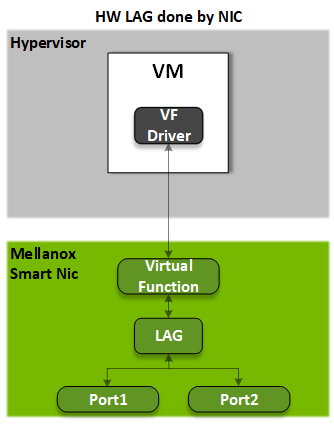
Nvidia ASAP2 technology extends legacy SRIOV capabilities by offloading LAG (link aggregation group) functionality to the Smart Network Interface Card (SmartNIC) hardware. This means that a VM can be attached with single VF backed up by LAG implemented on the NIC level.
This guide will highlight the benefits of having offloaded LAG functionality and walk you through configuration and evaluation of offloaded LAG on a standalone Linux server.
References
Solution Overview
There are few options to implement LAG in a virtual environment, depending on the system configuration and the performance needs:
|
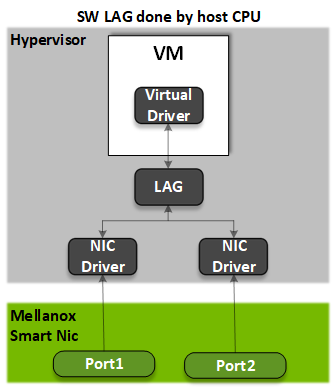
VM attached with virtual interface (virtio) to host LAG.
|
Figure 1
|
|
Figure 2 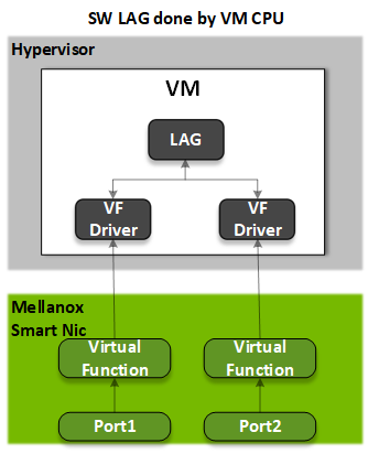
|
SRIOV is a default choice for network-demanding applications. In this case, Link Aggregation is performed within VM (VM aware LAG) and only HA mode may be implemented. |
|
SRIOV switchdev mode and ASAP2 (Accelerated Switching and Packet Processing®) are enhanced SR-IOV technologies which offload network processing from the Host and VM into the network adapter hardware.
|
Figure 3
|
Solution Logical Design
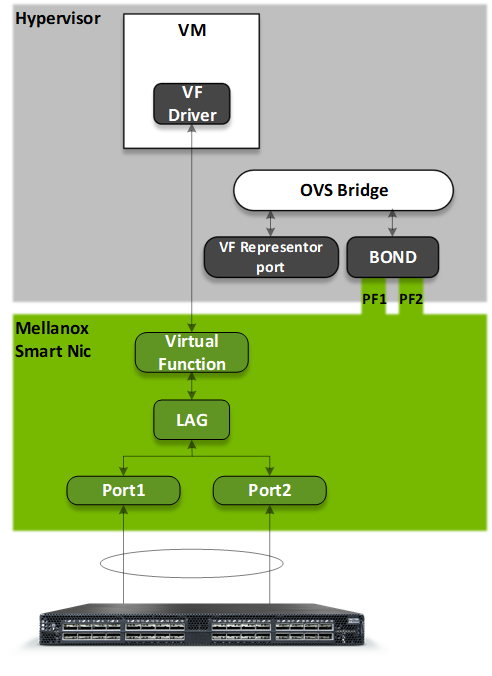
Referring to Figure 4, the two network interfaces from the NIC PFs are bounded in the hypervisor. The bond mode is reflected to all VFs of the same NIC. For example: If the BOND is, configured to LACP (Link Aggregation Control Protocol) mode then all VF LAG interfaces will share the same configuration.
To enable VF-LAG, the NIC should be in SRIOV switchdev mode. Unlike SRIOV legacy mode, switchdev mode requires a control plane to configure the steering and forwarding behavior of VFs. In this document we use OVS for this purpose. Please see OVS offload document for more details.
Figure 4
Host Configuration and Prerequisites
-
BIOS: VT-D and SRIOV enabled
-
OpenVswitch => 2.12
-
OS => RHEL 7.7
-
Kernel => 4.10
Host Deployment and Configuration
Set firmware to support SRIOV
First install the mstflint tool:
|
Extract PFs PCI BUS slot number:
|
Set firmware to enable SRIOV with number of desired VFs using PCI slot number taken from previous step:
|
Configure Linux bond
Configure the BOND interface.
This example demonstrates BOND LACP configuration:
|
Note
To learn more about bond modes please refer to:
https://www.cloudibee.com/network-bonding-modes/
Supported modes are 1, 2, 4.
Configure slave interfaces
Replace <first_interface_name>, <second_interface_name> with the respective PFs BOND slave names.
|
Restart network services
|
Enable ASAP2 VF-LAG capabilities
This example uses 2 VFs per PF (it is possible to configure more).
Extract PFs PCI BUS slot number:
|
Enable switchdev mode per each PF bond slave interface:
|
|
Once switchdev mode is enabled, new representor ports will be present in Linux bridge.
Now it is possible to discover representor ports mapping.
First download attached map_rep.py script from this section and run it as explained here:
|
Openvswitch settings
Add the desired representor ports to OpenVswitch bridge which represent the designated VFs:
|
Deployment Verification
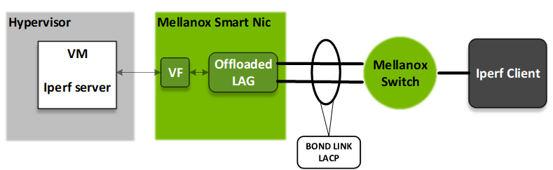
Test deployment (figure 5) overview:
Figure 5
-
First spawn up a guest VM with VF interface using SRIOV attachment based on VF PCI slot number.
Here is Virsh XML section for SRIOV interface attachment of VF with PCI slot number 0000:61:01.2<interface type='hostdev' managed='yes'> <mac address='6a:66:2d:48:92:c3'/> <source> <address type='pci' domain='0x0000' bus='0x61' slot='0x01' function='0x2'/> </source> <address type='pci' domain='0x0000' bus='0x00' slot='0x11' function='0x0'/> </interface> -
Set IP of 1.1.1.1 to the VF interface in the Guest VM.
-
Set IP of 1.1.1.2 to the Iperf client interface which is connected to L2 switch.
-
Make sure there is connectivity between the Iperf client to the guest VM by issuing ICMP requests.
-
Start iperf server on the Guest VM:
|
-
Start iperf client on the iperf client server:
|
-
Validate that packets are received and transmitted on both bond slaves.
From the guest VM hypervisor command line run:
|
-
Fail one of the bond links and repeat step 7. You will observe packet are received and transmitted only for single bond slave.
Tearing Down VF-LAG BOND
In case user would like to teardown VF-LAG BOND it is very important to follow this sequence:
-
First teardown VFs from a VM.
-
Unbind VF drivers as follows:
|
-
Undo steps for building VF-LAG BOND which are described in this post.
About the Author
|
|
Amir Zeidner For several years, Amir has worked as a Solutions Architect primarily in the Telco space, leading advanced solutions to answer 5G, NFV, and SDN networking infrastructure requirements. Amir’s expertise in data plane acceleration technologies, such as Accelerated Switching and Network Processing (ASAP²) and DPDK, together with a deep knowledge of open-source cloud-based infrastructures, allows him to promote and deliver unique end-to-end NVIDIA Networking solutions throughout the Telco world. |
Last updated: