Created on Sep 7, 2022
Scope
This article is covering the full design, scale considerations and deployment steps of the Canonical Charmed OpenStack cloud solution based on Ubuntu 22.04 with inbox network drivers and OpenStack Yoga packages over highly available 100GbE NVIDIA networking with OVN hardware acceleration.
Abbreviations and Acronyms
|
Term |
Definition |
Term |
Definition |
|---|---|---|---|
|
AI |
Artificial Intelligence |
ML2 |
Modular Layer 2 Openstack Plugin |
|
ASAP2 |
Accelerated Switching and Packet Processing® |
MLAG |
Multi-Chassis Link Aggregation |
|
BGP |
Border Gateway Protocol |
MLNX_OFED |
NVIDIA Mellanox OpenFabrics Enterprise Distribution for Linux (network driver) |
|
BOM |
Bill of Materials |
NFV |
Network Functions Virtualization |
|
CPU |
Central Processing Unit |
NIC |
Network Interface Card |
|
CUDA |
Compute Unified Device Architecture |
OS |
Operating System |
|
DHCP |
Dynamic Host Configuration Protocol |
OVN |
Open Virtual Network |
|
DPDK |
Data Plane Development Kit |
OVS |
Open vSwitch |
|
EVPN |
Ethernet VPN |
PF |
Physical Function |
|
EVPN-MH |
EVPN Multihoming |
RDG |
Reference Deployment Guide |
|
FW |
FirmWare |
RDMA |
Remote Direct Memory Access |
|
GPU |
Graphics Processing Unit |
RoCE |
RDMA over Converged Ethernet |
|
HA |
High Availability |
SDN |
Software Defined Networking |
|
IP |
Internet Protocol |
SR-IOV |
Single Root Input/Output Virtualization |
|
IPMI |
Intelligent Platform Management Interface |
VF |
Virtual Function |
|
L3 |
IP Network Layer 3 |
VF-LAG |
Virtual Function Link Aggregation |
|
LACP |
Link Aggregation Control Protocol |
VLAN |
Virtual LAN |
|
MGMT |
Management |
VM |
Virtual Machine |
Introduction
Canonical Charmed OpenStack is an enterprise cloud platform based on Ubuntu OS with OpenStack packages, and OpenStack Charmed Operators for simplified deployment and operations.
This Reference Deployment Guide (RDG) demonstrates a step by step full deployment of a multi-tenant Charmed OpenStack cloud solution for common as well as high performance workloads. The deployment uses Nvidia highly available 100GbE fabric with hardware accelerated ML2/OVN as SDN with stateful Firewall and NAT services.
The use cases covered in this article include Geneve for East-West traffic and Floating IP DNAT for North-South, both fully accelerated with cloud Security Policy enforcement at line rate.
The demonstrated benchmark validation tests can be used as a reference for multiple workload use cases such as NFV, Big Data and AI, TCP/UDP, DPDK, RoCE/RDMA and GPUDirect/RDMA stacks.
References
OpenStack Charms Deployment Guide
NVIDIA Cumulus EVPN-Multihoming
Data Plane Development Kit (DPDK) Home
Solution Architecture
Key Components and Technologies
-
NVIDIA A100 GPU
NVIDIA A100 Tensor Core GPU delivers unprecedented acceleration at every scale to power the world’s highest-performing elastic data centers for AI, data analytics, and HPC. Powered by the NVIDIA Ampere Architecture, A100 is the engine of the NVIDIA data center platform. A100 provides up to 20X higher performance over the prior generation and can be partitioned into seven GPU instances to dynamically adjust to shifting demands. Available in 40GB and 80GB memory versions, A100 80GB debuts the world’s fastest memory bandwidth at over 2 terabytes per second (TB/s) to run the largest models and datasets.
-
NVIDIA ConnectX SmartNICs
10/25/40/50/100/200 and 400G Ethernet Network Adapters
The industry-leading NVIDIA® ConnectX® family of smart network interface cards (SmartNICs) offer advanced hardware offloads and accelerations.
NVIDIA Ethernet adapters enable the highest ROI and lowest Total Cost of Ownership for hyperscale, public and private clouds, storage, machine learning, AI, big data, and telco platforms.
-
NVIDIA Cumulus Linux
NVIDIA® Cumulus® Linux is the industry's most innovative open network operating system that allows you to automate, customize, and scale your data center network like no other.
-
NVIDIA LinkX Cables
The NVIDIA® LinkX® product family of cables and transceivers provides the industry’s most complete line of 10, 25, 40, 50, 100, 200, and 400GbE in Ethernet and 100, 200 and 400Gb/s InfiniBand products for Cloud, HPC, hyperscale, Enterprise, telco, storage and artificial intelligence, data center applications.
-
Canonical Charmed OpenStack
Canonical Charmed OpenStack is an enterprise cost-effective cloud platform, designed to run mission-critical workloads for telcos, financial institutions, hardware manufacturers, government institutions and enterprise.
Logical Design
Image description: Logical Design Main Components
Note
In this reference design, we used dedicated nodes for MAAS and Juju controllers without any HA configuration. In general, It is possible to co-locate MAAS and Juju controllers on the same physical machines, and the controllers can also be configured for HA.
Image description: Logical Design OpenStack Components
Note
In this reference design, we configured one of the OpenStack nodes to serve as a dedicated "controller" running only OpenStack control services, and two nodes to run compute services and host VMs. Juju charms allows flexible application distribution across nodes.
The only OpenStack applications configured as HA cluster in the charm bundle used to deploy the solution described in this article, are OVN-Central and MySQL DB. A full-HA application deployment is supported as well by Canonical Charmed OpenStack.
Network Fabric Design
Reference Network Architecture
The reference network architecture used for the solution described in this Reference Deployment Guide contains the following building blocks:
-
Fully stretched EVPN Multihoming (EVPN-MH) networking architecture. It is a standards-based replacement for MLAG in data centers deploying CLOS topologies with many advantages over existing solutions - For more information, refer to NVIDIA Cumulus EVPN-MH
-
2 x MSN3700C Spine switches
-
2 x MSN3700C Leaf switches per rack with Multihoming configuration and without any inter-leafs peer-links.
-
Host servers with 2 x 100Gbps ports, configured with LACP Active-Active bonding
-
The bond interface is used in Openvswitch running on the Host
-
Multiple L3 Openvswitch VLAN interfaces are configured on the Host
-
The IP Subnets of the VLAN interfaces are mapped into MAAS spaces and used for Juju multi-space deployment
-
-
A converged and highly available 100GbE high speed fabric is used for all data, control, provisioning and management networks stretched over the datacenter using EVPN
-
1GbE dedicated IPMI fabric
-
MAAS node is configured as cloud components default gateway for internet access over the OAM network space
-
A dedicated node is configured as a default gateway of the Public network
-
MAAS and Juju Controller nodes were not deployed in server HA configuration or with bond networking
-
The entire fabric is configured to support Jumbo Frames (optional)
Image description: Reference Fabric Small Scale
Image description: Network Architecture Diagram
Note
-
The External Gateway node is using only as a default gateway for the Public network and not related to the VM's Floating IPs
-
For extreme message-rate workloads, additional network architectures, such as Routed Leaf Spine without an overlay, are available.
Large Scale
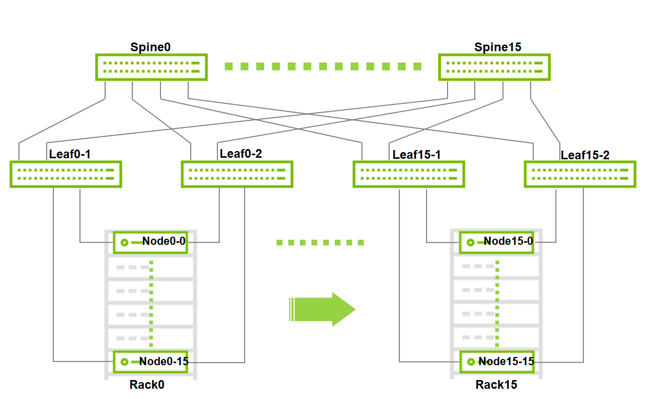
Image description: Large Scale Fabric
Note
Maximum Scale for 2 layers leaf spine fabric with the selected switches:
-
16 x MSN3700C switches as Spine
-
32 x MSN3700C switches as Leaf
-
16 x Racks
-
256 x Nodes (16 per rack)
This is a Non-Blocking scale topology without requiring any inter-leafs peer-link, due to EVPN-MH architecture.
Host Accelerated Bonding Logical Design
In the solution described in this article, enhanced SR-IOV with bonding support (ASAP2 VF-LAG) is used to offload network processing from the host and VM into the network adapter hardware, while providing fast data plane with high availability functionality.
Two Virtual Functions, each on a different physical port of the same NIC, are bonded and allocated to the VM as a single LAGed VF. The bonded interface is connected to a single or multiple ToR switches, using Active-Standby or Active-Active bond modes.
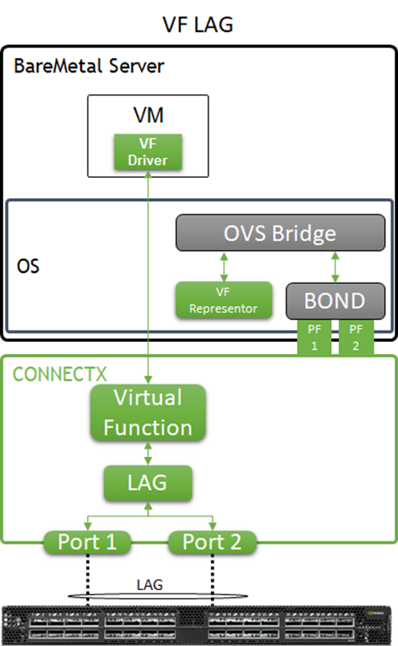
Image description: VF-LAG components
For additional information, please refer to QSG: High Availability with Mellanox ASAP2 Enhanced SR-IOV (VF-LAG)..
Host and Application Logical Design
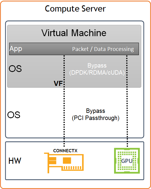
Image description: Host HW/SW Components
Compute host components:
-
NVIDIA A100 GPU Devices
-
NVIDIA ConnectX6-Dx High Speed NIC with a dual physical port, configured with LACP bonding in MLAG topology, and providing VF-LAG redundancy to the VM
-
Storage Drives for local OS usage
-
Ubuntu 22.04 as a base OS
-
OpenStack Yoga packages
-
Charmed OpenStack Platform software stack with:
-
KVM-based hypervisor
-
Openvswitch (OVS) with hardware offload support
-
ML2/OVN Mechanism Driver
-
Virtual Machine components:
-
Ubuntu 22.04 as base OS
-
NVIDIA GPU devices allocated using PCI passthrough, allowing to bypass the compute server hypervisor
-
NVIDIA SR-IOV Virtual Function (VF) allocated using PCI passthrough, allowing to bypass the compute server hypervisor
-
NVIDIA cUDA and MLNX_OFED drivers for GPUDirect RDMA use case
-
DPDK user space libraries for accelerated network processing use case with VM kernel bypass
-
Performance and benchmark testing toolset, including iperf3, dpdk-apps and perftest-tools
Software Stack Components
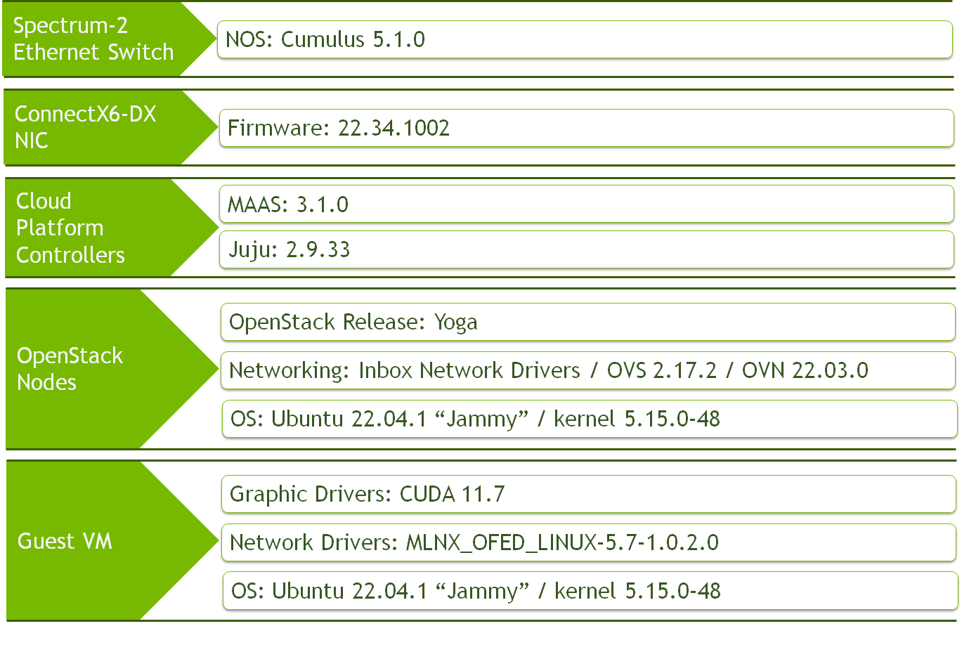
Image description: Solution SW Stack Components
Bill of Materials (BOM)
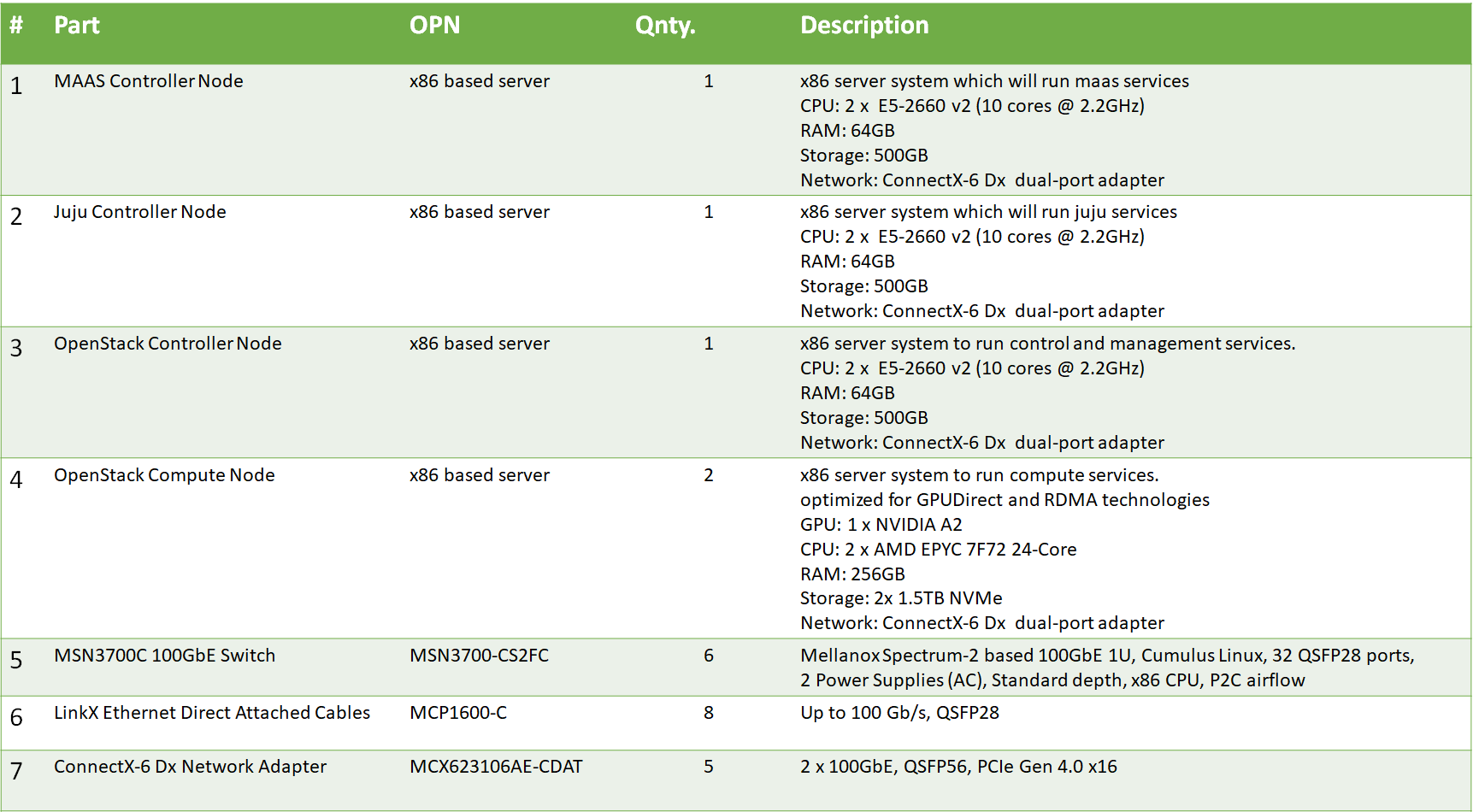
Image description: Bill of Material Inventory
Deployment and Configuration
Wiring
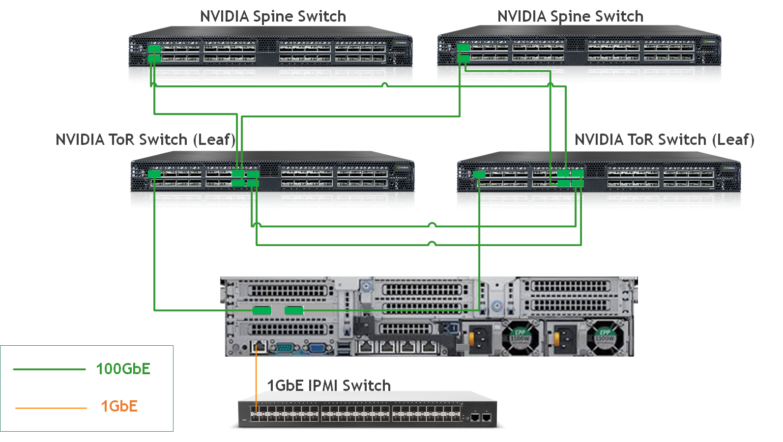
Image description: Deployment Wiring
Network Fabric
NIC Firmware Upgrade and Settings
Please make sure to upgrade the ConnectX NIC firmware to the latest release, as listed here.
There are multiple ways to update the NIC firmware. One or them is by installing the mstflint package on the server hosting the NIC - Firmware Update Instructions.
In the following RDG, firmware update is not automated as part of the deployment. However, MAAS commissioning scripts can be used for this purpose - for additional information, refer to Canonical MAAS Commissioning Script Reference
Switch NOS Upgrade
Please make sure to upgrade Cumulus Linux to the latest release. Use the following links for further instructions and details: Upgrading Cumulus Linux or Installing a New Cumulus Linux Image.
Note
Starting from Cumulus Linux 4.2.0, the default password for the cumulus user account has changed to "cumulus", and must be changed upon first login.
Switch Configuration - Summary
Note
The tables in this section are aimed to explain the switches configurations and naming terminology used in the full configuration files.
For example in Leaf switch "Leaf0-1" which is located in Rack 0, VLANs 10 which is used for Internal network, is configured on interface swp9-swp10 which are members in BOND interfaces bond1-bond2, respectively, with MTU of 9000. This bond is configured to use EVPN multihoming segment mac-address 44:38:39:BE:EF:01.
Detailed switch configuration can be found in the next sections, and the tables below are introduced as a complementary visual tool for the full configuration files.
Networks Identifiers
|
Network |
VLAN ID |
EVPN VNI |
MAAS Space |
|---|---|---|---|
|
PXE/OAM |
3000 |
3000 |
oam-space |
|
Public |
9 |
9 |
public-space |
|
Internal |
10 |
10 |
internal-space |
|
Geneve overlay tenant |
40 |
40 |
overlay-space |
|
Provider-vlan tenant |
101 |
101 |
N/A |
Leaf-Host Interfaces
|
Rack-Leaf |
Leaf Interface |
Bond Interface |
VLANs and Mode |
MTU |
MH Segment MAC |
|---|---|---|---|---|---|
|
0-1 |
swp9 |
bond1 |
Tagged: 10,40,101,9 Untagged: 3000 |
9000 |
44:38:39:BE:EF:01 |
|
0-1 |
swp10 |
bond2 |
Tagged: 10,40,101,9 Untagged: 3000 |
9000 |
44:38:39:BE:EF:01 |
|
0-1 |
swp22 |
bond_ext |
Untagged: 9 |
9000 |
44:38:39:BE:EF:01 |
|
0-1 |
swp23-24 |
N/A |
Tagged: 9, Untagged: 3000 |
9000 |
N/A |
|
0-2 |
swp9 |
bond1 |
Tagged: 10,40,101,9 Untagged: 3000 |
9000 |
44:38:39:BE:EF:01 |
|
0-2 |
swp10 |
bond2 |
Tagged: 10,40,101,9 Untagged: 3000 |
9000 |
44:38:39:BE:EF:01 |
|
0-2 |
swp22 |
bond_ext |
Untagged: 9 |
9000 |
44:38:39:BE:EF:01 |
|
1-1 |
swp9 |
bond1 |
Tagged: 10,40,101,9 Untagged: 3000 |
9000 |
44:38:39:BE:EF:02 |
|
1-1 |
swp10 |
bond2 |
Tagged: 10,40,101,9 Untagged: 3000 |
9000 |
44:38:39:BE:EF:02 |
|
1-2 |
swp9 |
bond1 |
Tagged: 10,40,101,9 Untagged: 3000 |
9000 |
44:38:39:BE:EF:02 |
|
1-2 |
swp10 |
bond2 |
Tagged: 10,40,101,9 Untagged: 3000 |
9000 |
44:38:39:BE:EF:02 |
Leaf-Spine Interfaces
|
Rack-Leaf |
Leaf Interfaces |
Spine0 Interface |
Spine1 Interface |
MTU |
|---|---|---|---|---|
|
0-1 |
swp31, swp32 |
swp13 |
swp13 |
9216 (default) |
|
0-2 |
swp31, swp32 |
swp14 |
swp14 |
9216 (default) |
|
1-1 |
swp31, swp32 |
swp15 |
swp15 |
9216 (default) |
|
1-2 |
swp31, swp32 |
swp16 |
swp16 |
9216 (default) |
Switch Interfaces Topology
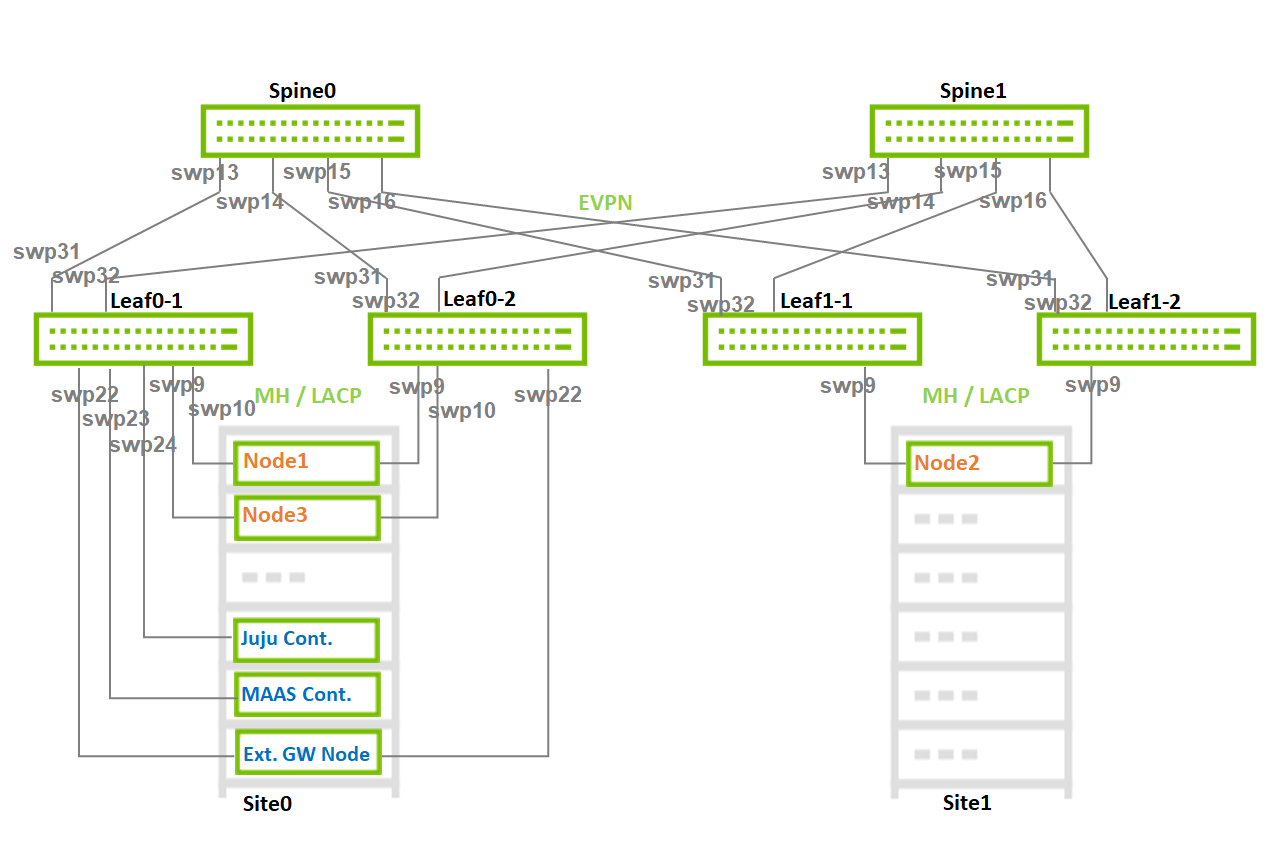
Image description: Switch Interfaces Topology
Switch Configuration - Detailed
Note
The configuration below is provided as an NVUE commands set, and is matching the reference network architecture used in this article.
Rack1 configuration contains two bond interfaces although only a single host is used in the current reference network architecture.
Leaf0-1
Leaf0-2
Leaf1-1
Leaf1-2
Spine0
Spine1
Verification
-
Confirm the interfaces status on the Leaf switches. Make sure all interfaces are UP and configured with the correct MTU. Verify the correct LLDP neighbors:
Leaf0-2
Leaf0-2$ net show int State Name Spd MTU Mode LLDP Summary ----- ---------- ---- ----- ---------- ----------------------------- ------------------------- UP lo N/A 65536 Loopback IP: 127.0.0.1/8 lo IP: 10.10.10.2/32 lo IP: ::1/128 UP eth0 1G 1500 Mgmt Master: mgmt(UP) eth0 IP: /24(DHCP) PRTDN swp1 N/A 9216 Default PRTDN swp2 N/A 9216 Default PRTDN swp3 N/A 9216 Default UP swp9 100G 9000 BondMember Master: bond1(UP) UP swp10 100G 9000 BondMember Master: bond2(UP) UP swp22 100G 9000 BondMember Master: bond_ext(UP) UP swp31 100G 9216 Default Spine0 (swp16) UP swp32 100G 9216 Default Spine1 (swp16) UP bond1 100G 9000 802.3ad Master: br_default(UP) bond1 Bond Members: swp9(UP) UP bond2 100G 9000 802.3ad Master: br_default(UP) bond2 Bond Members: swp10(UP) UP bond_ext 100G 9000 802.3ad Master: br_default(UP) bond_ext Bond Members: swp22(UP) UP br_default N/A 9216 Bridge/L2 UP mgmt N/A 65536 VRF IP: 127.0.0.1/8 mgmt IP: ::1/128 UP vxlan48 N/A 9216 Trunk/L2 Master: br_default(UP) -
Confirm the BGP/EVPN neighbors discovery on all switches:
Leaf0-2
Leaf0-2$ net show bgp summary
show bgp ipv4 unicast summary
=============================
BGP router identifier 10.10.10.2, local AS number 65102 vrf-id 0
BGP table version 18
RIB entries 11, using 2200 bytes of memory
Peers 2, using 46 KiB of memory
Peer groups 1, using 64 bytes of memory

Neighbor           V         AS   MsgRcvd   MsgSent   TblVer  InQ OutQ  Up/Down State/PfxRcd   PfxSnt
Spine0(swp31)      4      65199   1212494   1212671        0    0    0 05w3d22h            4        6
Spine11(swp32)     4      65199   1212534   1212696        0    0    0 05w3d22h            4        6

Total number of neighbors 2


show bgp ipv6 unicast summary
=============================
% No BGP neighbors found


show bgp l2vpn evpn summary
===========================
BGP router identifier 10.10.10.2, local AS number 65102 vrf-id 0
BGP table version 0
RIB entries 63, using 12 KiB of memory
Peers 2, using 46 KiB of memory
Peer groups 1, using 64 bytes of memory

Neighbor           V         AS   MsgRcvd   MsgSent   TblVer  InQ OutQ  Up/Down State/PfxRcd   PfxSnt
Spine0(swp31)      4      65199   1212494   1212671        0    0    0 05w3d22h          124      192
Spine11(swp32)     4      65199   1212534   1212696        0    0    0 05w3d22h          124      192

Total number of neighbors 2
Host
Prerequisites
-
Hardware specifications per host are described in the Bill Of Materials section.
-
ConnectX-6 Dx adapters configuration:
-
MAAS/Juju/OpenStack Controller Node
-
Latest Firmware
-
Ports are set to operate in Ethernet mode (LINK_TYPE_P0/1 Firmware parameter is set to ETH)
-
PXE boot enabled on the ports on Flexboot BIOS
-
-
OpenStack Compute Nodes
-
Latest Firmware
-
Ports are set to operate in Ethernet mode (LINK_TYPE_P0/1 Firmware parameter is set to ETH)
-
PXE boot enabled on the ports on Flexboot BIOS
-
SRIOV_EN firmware parameter is set to True
-
NUM_OF_VFS firmware parameter is set to a value matching the number of Virtual Functions used in the OpenStack bundle deployment file
-
ADVANCED_PCI_SETTINGS firmware parameter is set to True, and MAX_ACC_OUT_READ firmware parameter is set to a value of 44 for optimized bandwidth test results
-
ATS_ENABLED firmware parameter is set to True - For GPUDirect RDMA usage in Virtual Machines context
-
-
-
BIOS Configuration:
-
OpenStack Controller Nodes
-
PXE boot is set in server boot order
-
-
OpenStack Compute Nodes
-
Virtualization and SR-IOV enabled
-
Hyperthreading disabled
-
PXE boot is set in server boot order
-
ACS enabled - For GPUDirect RDMA usage in Virtual Machine
-
-
Cloud Deployment
MAAS Controller
MAAS Node Installation
-
Install Ubuntu 22.04 OS on the node, and log into it using SSH
-
Configure IP addresses on the interface connected to the high speed fabric
-
IP address from the PXE/OAM subnet (untagged) - In our case, we used 192.168.25.1
-
VLAN IP for the public subnet (in our case, VLAN ID 9)
-
-
-
Follow the instructions specified in the MAAS Installation Guide in order to complete the steps:
-
Install MAAS from a snap
-
Install and setup PostgreSQL
-
Initialize MAAS and verify the services are running
-
MAAS Node Configuration
-
Follow the instructions specified in the MAAS Installation Guide in order to complete the steps (Make sure to select "CLI" method under How to configure MAAS section):
-
Create an admin user
-
Generate an API-key, and login to MAAS CLI
-
Set an upstream DNS
-
Set up SSH for the admin user
-
Import images
-
Enable DHCP on the PXE untagged VLAN (subnet 192.168.25.0/24)
-
MAAS Networking Configuration
-
Login to MAAS UI and apply the following settings under the Subnets tab:
-
Locate the auto-discovered PXE/OAM fabric, and change its name to "fabric-high-speed". Make sure its untagged VLAN appears with MAAS-Provided DHCP
-
Add the following spaces:
-
oam-space
-
internal-space
-
overlay-space
-
public-space
-
-
Edit the fabric-high-speed untagged VLAN
-
Name: untagged-pxe-oam
-
Space: oam-space
-
MTU: 9000
-
-
Edit the fabric-high-speed Subnet
-
Name: pxe-oam-subnet
-
Gateway IP: 192.168.25.1
This is the IP address we assigned to the MAAS node on the interface connected to the high speed fabric, as in our solution example we use the MAAS node as the default Gateway of the deployed machines on the OAM network.
-
-
Add and edit the following VLANs
-
v9-public
-
VID: 9
-
Space: public-space
-
MTU: 9000
-
DHCP: Disabled
-
-
v10-internal
-
VID: 10
-
Space: internal-space
-
MTU: 9000
-
DHCP: Disabled
-
-
v40-overlay
-
VID: 40
-
Space: overlay-space
-
MTU: 9000
-
DHCP: Disabled
-
-
-
Add and edit the following Subnets
-
public-subnet
-
CIDR: 10.7.208.0/24
-
Fabric: fabric-high-speed
-
VLAN: 9(v9-public)
-
Reserved Ranges: per network requirements
In our solution example, public network IPs are assigned by the MAAS to the deployed machines. However, they are also assigned by OpenStack Neutron to the Virtual Instances as Floating IPs. Make sure to reserve the IP range used by Neutron.
-
-
internal-subnet
-
CIDR: 172.18.0.0/24
-
Fabric: fabric-high-speed
-
VLAN: 10(v10-internal)
-
-
overlay-subnet
-
CIDR: 172.16.0.0/24
-
Fabric: fabric-high-speed
-
VLAN: 40(v40-overlay)
-
-
-
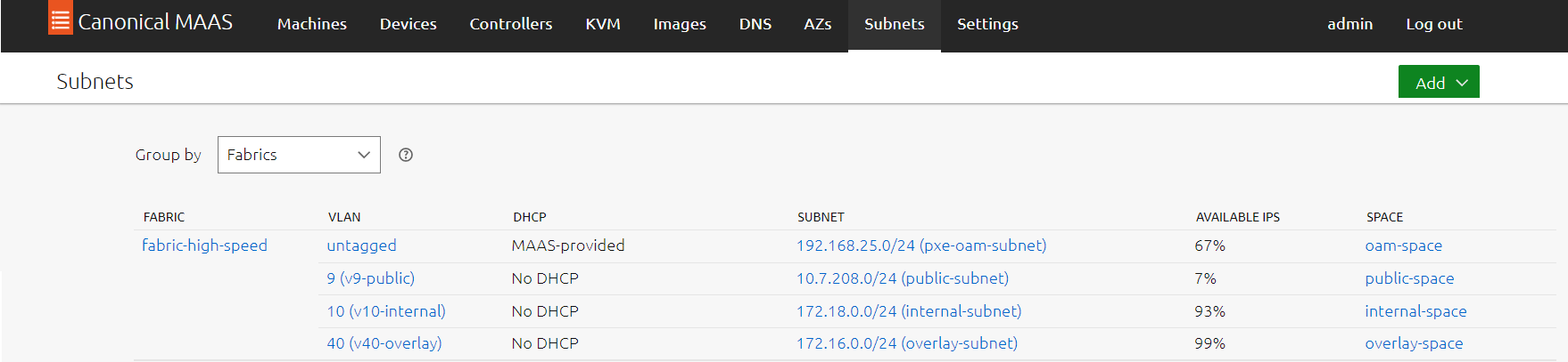
Image description: MAAS Fabrics
BareMetal MAAS Machines
Machines Inventory Creation and Commissioning
-
Under the MAAS UI "Machines" tab, add and commision four machines:
-
Juju Controller node
-
OpenStack Compute node 1
-
OpenStack Compute node 2
-
OpenStack Controller node
-
-
It is also possible to add and commision all machines by running the following maas-cli script on the MAAS node:
Edit the file below with the servers IPMI IPs, username and password.
#Juju controller
maas admin machines create \
    hostname=controller \
    architecture=amd64 \
    power_type=ipmi \
    power_parameters_power_driver=LAN_2_0 \
    power_parameters_power_user=***** \
    power_parameters_power_pass=***** \
    power_parameters_power_address=192.168.0.10

#OpenStack Compute servers

maas admin machines create \
    hostname=node1 \
    architecture=amd64 \
    power_type=ipmi \
    power_parameters_power_driver=LAN_2_0 \
    power_parameters_power_user=***** \
    power_parameters_power_pass=***** \
    power_parameters_power_address=192.168.0.11

maas admin machines create \
    hostname=node2 \
    architecture=amd64 \
    power_type=ipmi \
    power_parameters_power_driver=LAN_2_0 \
    power_parameters_power_user=***** \
    power_parameters_power_pass=***** \
    power_parameters_power_address=192.168.0.12

#Openstack Controller server

maas admin machines create \
    hostname=node3 \
    architecture=amd64 \
    power_type=ipmi \
    power_parameters_power_driver=LAN_2_0 \
    power_parameters_power_user=***** \
    power_parameters_power_pass=***** \
    power_parameters_power_address=192.168.0.13
ubuntu@maas-opstk:~$ chmod +x nodes-inventory.sh ubuntu@maas-opstk:~$ ./nodes-inventory.sh
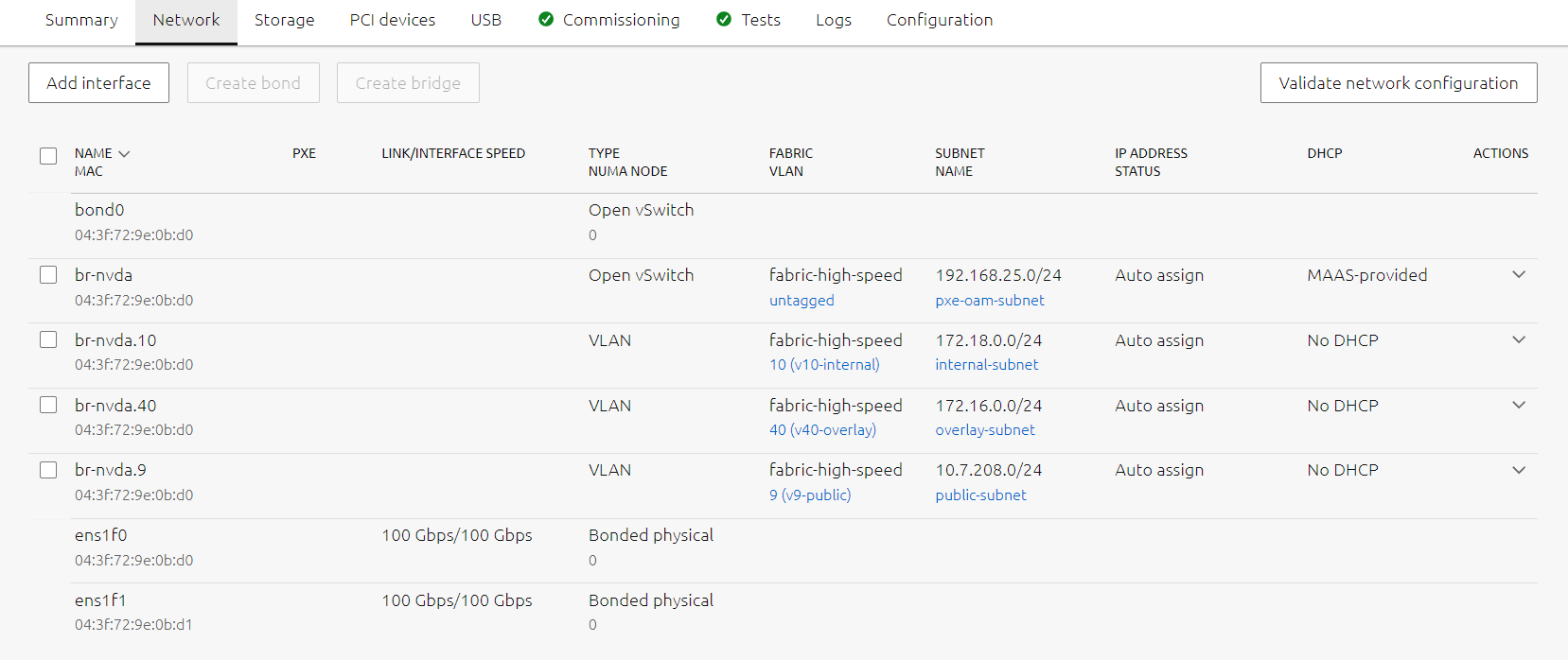
Machines Network Configuration
Note
The configuration below is using Open vSwitch bridge type in order to utilize the OVS-based HW Offload capabilities for all workloads and traffic types on the high speed NIC.
-
Once the machines are commissioned and in "Ready" state, proceed with the following Network configuration per machine:
-
controller (Juju Controller node)
-
Physical -> Edit: Fabric fabric-high-speed, VLAN untagged, Subnet pxe-oam-subnet, IP Mode Auto assign
-
Physical -> Add VLAN: VLAN v9-public, Subnet public-subnet, IP Mode Auto assign
-
-
node1 (OpenStack Compute node 1)
-
2 x Physical -> Create Bond: Name bond0, Bond mode 802.3ad, IP Mode Unconfigured
-
bond0 -> Create Bridge: Name br-nvda, Type Open vSwitch (ovs), Fabric fabric-high-speed, VLAN untagged, Subnet pxe-oam-subnet, IP Mode Auto assign
-
br-nvda -> Add VLAN: VLAN v9-public, Subnet public-subnet, IP Mode Auto assign
-
br-nvda -> Add VLAN: VLAN v10-internal, Subnet internal-subnet, IP Mode Auto assign
-
br-nvda -> Add VLAN: VLAN v40-overlay, Subnet overlay-subnet, IP Mode Auto assign
-
-
node2 (OpenStack Compute node 2)
-
2 x Physical -> Create Bond: Name bond0, Bond mode 802.3ad, IP Mode Unconfigured
-
bond0 -> Create Bridge: Name br-nvda, Type Open vSwitch (ovs), Fabric fabric-high-speed, VLAN untagged, Subnet pxe-oam-subnet, IP Mode Auto assign
-
br-nvda -> Add VLAN: VLAN v9-public, Subnet public-subnet, IP Mode Auto assign
-
br-nvda -> Add VLAN: VLAN v10-internal, Subnet internal-subnet, IP Mode Auto assign
-
br-nvda -> Add VLAN: VLAN v40-overlay, Subnet overlay-subnet, IP Mode Auto assign
-
-
node 3 (OpenStack Controller node)
-
2 x Physical -> Create Bond: Name bond0, Bond mode 802.3ad, IP Mode Unconfigured
-
bond0 -> Create Bridge: Name br-nvda, Type Open vSwitch (ovs), Fabric fabric-high-speed, VLAN untagged, Subnet pxe-oam-subnet, IP Mode Auto assign
-
br-nvda -> Add VLAN: VLAN v9-public, Subnet public-subnet, IP Mode Auto assign
-
br-nvda -> Add VLAN: VLAN v10-internal, Subnet internal-subnet, IP Mode Auto assign
-
br-nvda -> Add VLAN: VLAN v40-overlay, Subnet overlay-subnet, IP Mode Auto assign
-
The image below is an example for node network configuration:
-
-
Machines Tagging
-
Create Tags and assign to the machines according to their roles.
In the example below, the MAAS CLI is used for creating and assigning tags. It is also possible to use the MAAS UI.
-
Create new tags.
ubuntu@maas-opstk:~$ maas admin tags create name=juju comment="Juju Controller" ubuntu@maas-opstk:~$ maas admin tags create name=controller comment="OpenStack Controller" ubuntu@maas-opstk:~$ maas admin tags create name=compute_sriov comment="Performance tuning kernel parameters" kernel_opts="default_hugepagesz=1G hugepagesz=1G hugepages=96 intel_iommu=on iommu=pt blacklist=nouveau rd.blacklist=nouveau isolcpus=2-23"The compute nodes tag includes kernel parameters setting for performance tuning, such as hugepages and isolated CPUs. The isolated cores are correlated with OpenStack Nova cpu-dedicated-set configuration used in the charm deployment bundle.
-
Identify machines system IDs:
ubuntu@maas-opstk:~$ sudo apt install jq ubuntu@maas-opstk:~$ maas admin machines read | jq '.[] | .hostname, .system_id' "controller" "nsfyqw" "node1" "gxmyax" "node2" "yte7xf" "node3" "s67rep" -
Assign tags to the relevant machines using its system IDs:
ubuntu@maas-opstk:~$ maas admin tag update-nodes juju add=nsfyqw
ubuntu@maas-opstk:~$ maas admin tag update-nodes controller add=s67rep
ubuntu@maas-opstk:~$ maas admin tag update-nodes compute_sriov add=gxmyax add=yte7xf
-
Juju Controller Bootstrap
-
Bootstrap the juju controller machine tagged with "juju":
ubuntu@maas-opstk:~$ juju bootstrap --bootstrap-series=focal --constraints tags=juju mymaas maas-controller --debug
OpenStack Charm Bundle File Configuration
-
The following "openstack-bundle-jammy-multi-space-nvidia-network.yaml" bundle file was used in our solution to allow our desired deployment according to the solution design guidelines. It includes the following main characteristics:
-
Jammy-based OS image for the deployed nodes with OpenStack Yoga
-
Multi-space charms configuration matching the solution network design
-
2 x Compute machines, 1 x Control machine
-
Hardware Offload Enabled
-
NVIDIA CX6-Dx and A100 GPU in NOVA PCI whitelist for device passthrough allocation
-
Hybrid VF Pool (NVIDIA CX6-Dx PFs are used for both Geneve overlay and vlan-provider accelerated VFs)
-
Dedicated CPU cores from the same NUMA node associated with the NVIDIA ConnectX6-Dx NIC for enhanced performance VMs
-
Jumbo MTU
-
OpenStack Cloud Deployment
-
Verify the MAAS configured spaces were loaded by juju:
ubuntu@maas-opstk:~$ juju spaces Name Space ID Subnets alpha 0 oam-space 1 192.168.25.0/24 public-space 2 10.7.208.0/24 overlay-space 3 172.16.0.0/24 internal-space 4 172.18.0.0/24Run "juju reload-spaces" to force the operation in case it was not loaded.
-
Create a new model for the OpenStack cloud deployment:
ubuntu@maas-opstk:~$ juju add-model --config default-series=focal openstack -
Deploy the OpenStack cloud using the prepared deployment bundle file:
ubuntu@maas-opstk:~$ juju deploy ./openstack-bundle-jammy-multi-space-nvidia-network.yaml -
Follow deployment progress and status:
ubuntu@maas-opstk:~$ juju debug-log --replay
ubuntu@maas-opstk:~$ juju status
Post Deployment Operations
-
Once the deployment is stabilized, and the "juju status" indicates all applications are Active, collect the Vault app Public Address from the output, and proceed with the actions below.
Vault Initialization/CA Certificate
-
Install the vault client on the MAAS node:
ubuntu@maas-opstk:~$ sudo snap install vault -
Initialize Vault:
ubuntu@maas-opstk:~$ export VAULT_ADDR="http://<Vault App Public Address>:8200" ubuntu@maas-opstk:~$ vault operator init -key-shares=5 -key-threshold=3 -
Unseal Vault:
ubuntu@maas-opstk:~$ vault operator unseal <Key1> ubuntu@maas-opstk:~$ vault operator unseal <Key2> ubuntu@maas-opstk:~$ vault operator unseal <Key3> -
Authorize the Vault Charm:
ubuntu@maas-opstk:~$ export VAULT_TOKEN=<Vault Initial Root Token> ubuntu@maas-opstk:~$ vault token create -ttl=10m ubuntu@maas-opstk:~$ juju run-action --wait vault/leader authorize-charm token=$VAULT_TOKEN -
Add CA certificate:
ubuntu@maas-opstk:~$ juju run-action --wait vault/leader generate-root-ca -
Monitor the "juju status" output until all units are in Ready state:
ubuntu@maas-opstk:~$ juju statusFor more details regarding Vault initialization and adding CA certificate, refer to:
https://opendev.org/openstack/charm-vault/src/branch/master/src/README.md#post-deployment-tasks
https://docs.openstack.org/charm-guide/latest/admin/security/tls.html#add-a-ca-certificate
SR-IOV and Hardware Acceleration Enablement Verification
-
The following file should be created on each compute node after the ovn-chassis app is ready:
/etc/netplan/150-charm-ovn.yaml
############################################################################### # [ WARNING ] # Configuration file maintained by Juju. Local changes may be overwritten. # Config managed by ovn-chassis charm ############################################################################### network: version: 2 ethernets: enp63s0f0: virtual-function-count: 8 embedded-switch-mode: switchdev delay-virtual-functions-rebind: true enp63s0f1: virtual-function-count: 8 embedded-switch-mode: switchdev delay-virtual-functions-rebind: true -
For optimal performance benchmark, increase the number of NIC MSIX queues per SR-IOV Virtual Function on every compute node
-
Install the mstflint package.
# apt install mstflint -y -
Locate the Connect-X Adapter PCI ID.
root@node1:/home/ubuntu# lspci | grep -i nox 3f:00.0 Ethernet controller: Mellanox Technologies MT2892 Family [ConnectX-6 Dx] 3f:00.1 Ethernet controller: Mellanox Technologies MT2892 Family [ConnectX-6 Dx] -
Configure NUM_VF_MSIX NIC FW Parameter
root@node1:/home/ubuntu# mstconfig -d 3f:00.0 s NUM_VF_MSIX=63

Device #1:
----------

Device type:    ConnectX6DX
Name:           MCX623106AC-CDA_Ax
Description:    ConnectX-6 Dx EN adapter card; 100GbE; Dual-port QSFP56; PCIe 4.0 x16; Crypto and Secure Boot
Device:         3f:00.0

Configurations:                              Next Boot       New
         NUM_VF_MSIX                         11              63

 Apply new Configuration? (y/n) [n] : y
Applying... Done!
-I- Please reboot machine to load new configurations.
-
-
In order to apply the SR-IOV and hardware acceleration configuration, reboot the compute nodes, one at a time:
root@node1:/home/ubuntu# reboot -
After the compute node boots up, verify the configuration was applied:
root@node1:/home/ubuntu# lspci | grep -i nox 3f:00.0 Ethernet controller: Mellanox Technologies MT2892 Family [ConnectX-6 Dx] 3f:00.1 Ethernet controller: Mellanox Technologies MT2892 Family [ConnectX-6 Dx] 3f:00.2 Ethernet controller: Mellanox Technologies ConnectX Family mlx5Gen Virtual Function 3f:00.3 Ethernet controller: Mellanox Technologies ConnectX Family mlx5Gen Virtual Function 3f:00.4 Ethernet controller: Mellanox Technologies ConnectX Family mlx5Gen Virtual Function 3f:00.5 Ethernet controller: Mellanox Technologies ConnectX Family mlx5Gen Virtual Function 3f:00.6 Ethernet controller: Mellanox Technologies ConnectX Family mlx5Gen Virtual Function 3f:00.7 Ethernet controller: Mellanox Technologies ConnectX Family mlx5Gen Virtual Function 3f:01.0 Ethernet controller: Mellanox Technologies ConnectX Family mlx5Gen Virtual Function 3f:01.1 Ethernet controller: Mellanox Technologies ConnectX Family mlx5Gen Virtual Function 3f:08.2 Ethernet controller: Mellanox Technologies ConnectX Family mlx5Gen Virtual Function 3f:08.3 Ethernet controller: Mellanox Technologies ConnectX Family mlx5Gen Virtual Function 3f:08.4 Ethernet controller: Mellanox Technologies ConnectX Family mlx5Gen Virtual Function 3f:08.5 Ethernet controller: Mellanox Technologies ConnectX Family mlx5Gen Virtual Function 3f:08.6 Ethernet controller: Mellanox Technologies ConnectX Family mlx5Gen Virtual Function 3f:08.7 Ethernet controller: Mellanox Technologies ConnectX Family mlx5Gen Virtual Function 3f:09.0 Ethernet controller: Mellanox Technologies ConnectX Family mlx5Gen Virtual Function 3f:09.1 Ethernet controller: Mellanox Technologies ConnectX Family mlx5Gen Virtual Function root@node1:/home/ubuntu# lspci | grep "Virtual Function" | wc -l 16 root@node1:/home/ubuntu# devlink dev eswitch show pci/0000:3f:00.0 pci/0000:3f:00.0: mode switchdev inline-mode none encap-mode basic root@node1:/home/ubuntu# devlink dev eswitch show pci/0000:3f:00.1 pci/0000:3f:00.1: mode switchdev inline-mode none encap-mode basic -
Monitor the "juju status" output, and verify all units and applications are recovered:
ubuntu@maas-opstk:~$ juju status
QoS Settings
-
Apply the following QoS configuration on both compute nodes:
Note
The following configuration section is required for optimal RDMA benchmark testing using Lossless RoCE configuration,and it is tuned for prioritizing a specific DSCP marker that will be used later on in the benchmark test.
Please notice it will not survive a reboot.
-
Login to the compute nodes:
ubuntu@maas-opstk:~$ juju ssh 0 -
Configure OVS to copy the inner DSCP into the Geneve encapsulated header:
root@node1:/home/ubuntu# ovs-vsctl set Open_vSwitch . external_ids:ovn-encap-tos=inherit -
Configure both physical bond interfaces with PFC/DSCP configuration adjusted for RDMA:
root@node1:/home/ubuntu# apt-get install python2
root@node1:/home/ubuntu# git clone https://github.com/Mellanox/mlnx-tools
root@node1:/home/ubuntu# cd mlnx-tools/python/
root@node1:/home/ubuntu# cat /proc/net/bonding/bond0 | grep "Slave Int"
Slave Interface: enp63s0f0
Slave Interface: enp63s0f1
root@node1:/home/ubuntu# python2 mlnx_qos -i enp63s0f0 --trust=dscp --pfc=0,0,0,1,0,0,0,0
root@node1:/home/ubuntu# python2 mlnx_qos -i enp63s0f1 --trust=dscp --pfc=0,0,0,1,0,0,0,0
OpenStack Cloud Operations Verification
-
Install OpenStack client on the MAAS node:
ubuntu@maas-opstk:~$ sudo apt install python3-openstackclient -y -
Create cloud access credentials:
ubuntu@maas-opstk:~$ sudo git clone https://github.com/openstack-charmers/openstack-bundles ~/openstack-bundles ubuntu@maas-opstk:~$ source ~/openstack-bundles/stable/openstack-base/openrc -
Confirm you can access the cloud from the command line:
ubuntu@maas-opstk:~$ openstack service list

+----------------------------------+-----------+-----------+
| ID                               | Name      | Type      |
+----------------------------------+-----------+-----------+
| 23fe81313c3b476cbf5bd29d5f0570fe | nova      | compute   |
| bb0783870a314bd0a171c3714d7cf44b | neutron   | network   |
| d3060dd804184a98b91e79191c27b8e3 | keystone  | identity  |
| d5c3d2c0b3f04602b728fc1480eee879 | glance    | image     |
| d946299bca114c6c9e16ffe3109bf7e1 | placement | placement |
+----------------------------------+-----------+-----------+
Applications and Use Cases
Accelerated OVN Packet Processing (SDN Acceleration)
Note
The following use cases demonstrate SDN layer acceleration using hardware offload capabilities. The tests include a Telco grade benchmark that aims to push SDN offload into optimal performance and validate its functionality.
Use Case Topology
The following topology describes VM instances located on remote compute nodes with hardware accelerated bond, and running different workloads over Geneve overlay tenant network.
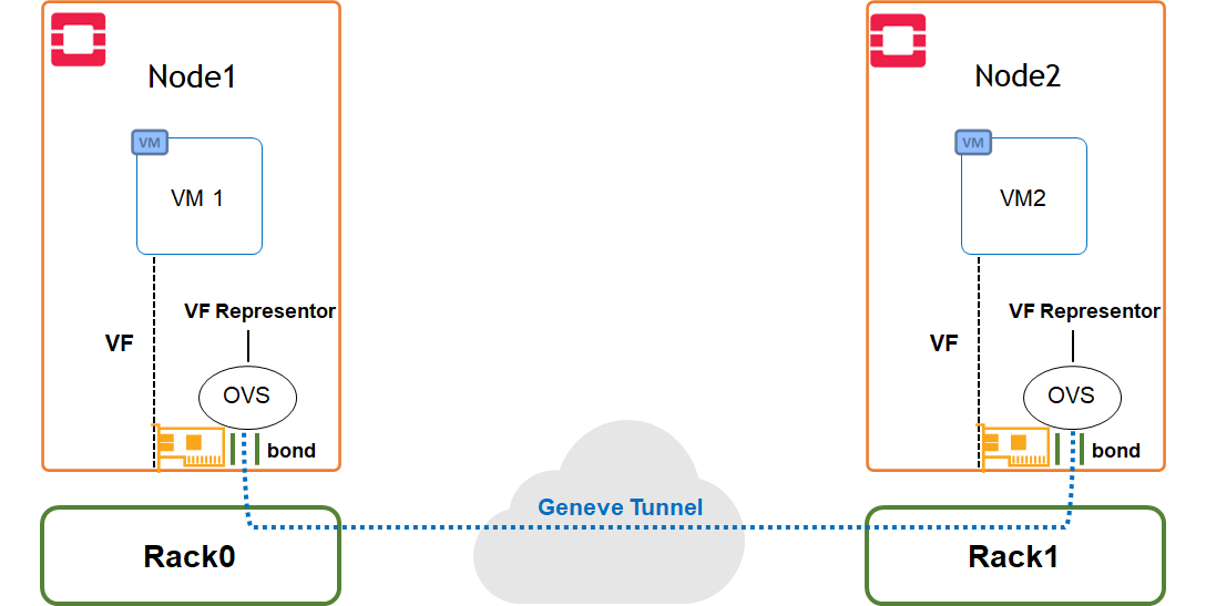
Image description: SDN Acceleration Use Case Topology
Use Case Configuration
VM image
-
Upload the Ubuntu VM cloud image to the image store:
The VM image was built using a disk-image-builder tool. The following article can be used as a reference: How-to: Create OpenStack Cloud Image with NVIDIA GPU and Network Drivers.
$ openstack image create --container-format bare --disk-format qcow2 --file ~/images/ubuntu-perf.qcow2 ubuntu-perf
VM Flavor
-
Create a flavor:
$ openstack flavor create m1.packet --ram 8192 --disk 20 --vcpus 20 -
Set hugepages and cpu-pinning parameters:
$ openstack flavor set m1.packet --property hw:mem_page_size=large
$ openstack flavor set m1.packet --property hw:cpu_policy=dedicated
Security Policy
-
Create a stateful security group policy to apply on the management network ports:
$ openstack security group create mgmt_policy $ openstack security group rule create mgmt_policy --protocol tcp --ingress --dst-port 22 -
Create a stateful security group policy to apply on the data network ports:
$ openstack security group create data_policy
$ openstack security group rule create data_policy --protocol icmp --ingress
$ openstack security group rule create data_policy --protocol icmp --egress
SSH Keys
-
Create an SSH key pair:
$ openstack keypair create --public-key ~/.ssh/id_rsa.pub bastion
VM Networks and Ports
-
Create a management overlay network:
$ openstack network create gen_mgmt --provider-network-type geneve --share $ openstack subnet create gen_mgmt_subnet --dhcp --network gen_mgmt --subnet-range 22.22.22.0/24 -
Create 2 normal management network ports with management security policy:
$ openstack port create normal1 --network gen_mgmt --security-group mgmt_policy $ openstack port create normal2 --network gen_mgmt --security-group mgmt_policy -
Create a data overlay network:
$ openstack network create gen_data --provider-network-type geneve --share $ openstack subnet create gen_data_subnet --dhcp --network gen_data --subnet-range 33.33.33.0/24 --gateway none -
Create 3 data network accelerated ports with data security policy:
$ openstack port create direct_overlay1 --vnic-type=direct --network gen_data --binding-profile '{"capabilities":["switchdev"]}' --security-group data_policy
$ openstack port create direct_overlay2 --vnic-type=direct --network gen_data --binding-profile '{"capabilities":["switchdev"]}' --security-group data_policy
VM Instances
-
Create 2 VM instances, one on each compute node:
$ openstack server create --key-name bastion --flavor m1.packet --image ubuntu-perf --port normal1 --port direct_overlay1 vm1 --availability-zone nova:node1.maas

$ openstack server create --key-name bastion --flavor m1.packet --image ubuntu-perf --port normal2 --port direct_overlay2 vm2 --availability-zone nova:node2.maas
VM Public Access
-
Create a vlan-provider external network and subnet:
Make sure to use the VLAN ID configured in the network for allowing public access. In our solution VLAN ID 9 is used.
$ openstack network create vlan_public --provider-physical-network tenantvlan --provider-network-type vlan --provider-segment 9 --share --external $ openstack subnet create public_subnet --no-dhcp --network vlan_public --subnet-range 10.7.208.0/24 --allocation-pool start=10.7.208.65,end=10.7.208.85 --gateway 10.7.208.1 -
Create a public router, and attach the public and the management subnets:
$ openstack router create public_router $ openstack router set public_router --external-gateway vlan_public $ openstack router add subnet public_router gen_mgmt_subnet -
Create Floating IPs from the public subnet range, and attach them to the VM instances:
$ openstack floating ip create --floating-ip-address 10.7.208.90 vlan_public
$ openstack floating ip create --floating-ip-address 10.7.208.91 vlan_public
$ openstack server add floating ip vm1 10.7.208.90
$ openstack server add floating ip vm2 10.7.208.91
Use Case Setup Validation
-
Verify that the instances were created successfully:
$ penstack server list +--------------------------------------+------+--------+-----------------------------------------------------------+-------------+-----------+ | ID | Name | Status | Networks | Image | Flavor | +--------------------------------------+------+--------+-----------------------------------------------------------+-------------+-----------+ | d19fe378-01a8-4b5e-ab7b-dd2c85edffbf | vm1 | ACTIVE | gen_data=33.33.33.219; gen_mgmt=10.7.208.90, 22.22.22.220 | ubuntu-perf | m1.packet | | 3747aa17-6a97-4bde-9fbe-bd553155a73c | vm2 | ACTIVE | gen_data=33.33.33.84; gen_mgmt=10.7.208.91, 22.22.22.181 | ubuntu-perf | m1.packet | +--------------------------------------+------+--------+-----------------------------------------------------------+-------------+-----------+ -
Login to the VM's Floating IPs using the relevant SSH key:
$ ssh -i ~/.ssh/id_rsa 10.7.208.90 $ ssh -i ~/.ssh/id_rsa 10.7.208.91 -
Verify that the VM instances can ping each other over the accelerated data interface:
$ ubuntu@vm1:~$ ping -c 4 33.33.33.84 PING 33.33.33.84 (33.33.33.84) 56(84) bytes of data. 64 bytes from 33.33.33.84: icmp_seq=1 ttl=64 time=0.492 ms 64 bytes from 33.33.33.84: icmp_seq=2 ttl=64 time=0.466 ms 64 bytes from 33.33.33.84: icmp_seq=3 ttl=64 time=0.437 ms 64 bytes from 33.33.33.84: icmp_seq=4 ttl=64 time=0.387 ms --- 33.33.33.84 ping statistics --- 4 packets transmitted, 4 received, 0% packet loss, time 3075ms rtt min/avg/max/mdev = 0.387/0.445/0.492/0.038 ms -
Verify Jumbo Frame connectivity over the accelerated data network:
[root@vm1:/home/ubuntu# ip link show ens5 | grep mtu 3: ens5: <BROADCAST,MULTICAST,UP,LOWER_UP> mtu 8942 qdisc mq state UP mode DEFAULT group default qlen 1000 root@vm1:/home/ubuntu# ping -M do -s 8914 33.33.33.84 PING 33.33.33.84 (33.33.33.84) 8914(8942) bytes of data. 8922 bytes from 33.33.33.84: icmp_seq=1 ttl=64 time=0.295 ms 8922 bytes from 33.33.33.84: icmp_seq=2 ttl=64 time=0.236 ms 8922 bytes from 33.33.33.84: icmp_seq=3 ttl=64 time=0.236 ms 8922 bytes from 33.33.33.84: icmp_seq=4 ttl=64 time=0.214 ms ^C --- 33.33.33.84 ping statistics --- 4 packets transmitted, 4 received, 0% packet loss, time 3053ms rtt min/avg/max/mdev = 0.214/0.245/0.295/0.030 ms -
Verify that the security policy is enforced on the data network by trying to establish iperf connection between the instances - Such a connection should be blocked:
root@vm2:/home/ubuntu# iperf3 -s -p 5101
-----------------------------------------------------------
Server listening on 5101
-----------------------------------------------------------
root@vm1:/home/ubuntu# iperf3 -c 33.33.33.84 -p 5101 tcp connect failed: Connection timed out -
Add to the data security policy a rule allowing iperf TCP ports:
$ openstack security group rule create data_policy --protocol tcp --ingress --dst-port 5001:5200 -
Verify that iperf connection is now allowed:
root@vm2:/home/ubuntu# iperf3 -s -p 5101
-----------------------------------------------------------
Server listening on 5101
-----------------------------------------------------------
root@vm1:/home/ubuntu# iperf3 -c 33.33.33.84 -p 5101 Connecting to host 33.33.33.84, port 5101 [ 5] local 33.33.33.219 port 47498 connected to 33.33.33.84 port 5101 [ ID] Interval Transfer Bitrate Retr Cwnd [ 5] 0.00-1.00 sec 4.42 GBytes 38.0 Gbits/sec 0 2.20 MBytes [ 5] 1.00-2.00 sec 4.24 GBytes 36.5 Gbits/sec 0 2.42 MBytes [ 5] 2.00-3.00 sec 4.47 GBytes 38.4 Gbits/sec 0 2.42 MBytes [ 5] 3.00-4.00 sec 4.47 GBytes 38.4 Gbits/sec 0 2.54 MBytes [ 5] 4.00-5.00 sec 4.08 GBytes 35.1 Gbits/sec 0 2.54 MBytes [ 5] 5.00-6.00 sec 4.66 GBytes 40.0 Gbits/sec 0 2.54 MBytes [ 5] 6.00-7.00 sec 4.13 GBytes 35.5 Gbits/sec 0 2.54 MBytes [ 5] 7.00-8.00 sec 4.65 GBytes 39.9 Gbits/sec 0 2.54 MBytes [ 5] 8.00-9.00 sec 4.66 GBytes 40.1 Gbits/sec 0 2.54 MBytes [ 5] 9.00-10.00 sec 4.67 GBytes 40.1 Gbits/sec 0 2.54 MBytes - - - - - - - - - - - - - - - - - - - - - - - - - [ ID] Interval Transfer Bitrate Retr [ 5] 0.00-10.00 sec 44.5 GBytes 38.2 Gbits/sec 0 sender [ 5] 0.00-10.04 sec 44.5 GBytes 38.0 Gbits/sec receiver -
Verify that the iperf traffic is offloaded to the hardware by capturing traffic on the physical bond interfaces used for Geneve encapsulation:
root@node1:/home/ubuntu# tcpdump -en -i enp63s0f0 vlan 40 | grep 5101 root@node1:/home/ubuntu# tcpdump -en -i enp63s0f1 vlan 40 | grep 5101-
Only the first connection packets that are flowing via slow path until the connection is offloaded to the hardware will be seen in the capture.
-
Hardware Offload of North-South NAT traffic over the Floating IP can be validated as well using the same method
-
Use Case Benchmarks
TCP Throughput
The following section is describing an iperf3 TCP throughput benchmark test between two VMs hosted on remote compute nodes with hardware acceleration and the configuration steps required to assure an optimized result over the accelerated bond used topology.
Note
The performance results listed in this document are indicative and should not be considered as formal performance targets for NVIDIA products.
-
Create 2 VM instances as instructed in previous steps:
The VM image used for this test is based on Ubuntu 22.04 and includes iperf3 and sysstat packages
-
On both compute nodes hosting the VM instances, verify that CPU pinning was applied and that the VM was allocated with host isolated cores on the same NUMA node as the NIC (2-23 in this case):
#root@node2:/home/ubuntu# virsh list --all
 Id   Name                State
-----------------------------------
 4    instance-00000008   running

root@node2:/home/ubuntu# virsh vcpupin 4
 VCPU   CPU Affinity
----------------------
 0      2
 1      5
 2      11
 3      8
 4      14
 5      17
 6      23
 7      20
 8      4
 9      15
 10     7
 11     10
 12     16
 13     13
 14     19
 15     22
 16     12
 17     3
 18     9
 19     6

root@node2:/home/ubuntu# numactl -H
available: 2 nodes (0-1)
node 0 cpus: 0 1 2 3 4 5 6 7 8 9 10 11 12 13 14 15 16 17 18 19 20 21 22 23
node 0 size: 128784 MB
node 0 free: 93679 MB
node 1 cpus: 24 25 26 27 28 29 30 31 32 33 34 35 36 37 38 39 40 41 42 43 44 45 46 47
node 1 size: 129012 MB
node 1 free: 92576 MB
node distances:
node   0   1
  0:  10  32
  1:  32  10

root@node2:/home/ubuntu# cat /proc/cmdline
BOOT_IMAGE=/boot/vmlinuz-5.15.0-48-generic root=UUID=19167c2d-e067-44a7-9176-2c784af688bc ro default_hugepagesz=1G hugepagesz=1G hugepages=64 intel_iommu=on iommu=pt blacklist=nouveau rd.blacklist=nouveau isolcpus=2-23
In our example, the ConnectX NIC is associated with Numa node 0, which is hosting CPU cores 0-23.
Cores 2-23 were isolated from the hypervisor (grub file), and dedicated to Nova instance usage (see "cpu-dedicated-set" in the cloud deployment bundle file).
-
On the VM instances, verify that the number of accelerated interface channels (MSIX queues) is identical to the number of vCPUs allocated to the VM (20 in this case):
root@vm1:/home/ubuntu# ethtool -l ens5 Channel parameters for ens5: Pre-set maximums: RX: n/a TX: n/a Other: n/a Combined: 20 Current hardware settings: RX: n/a TX: n/a Other: n/a Combined: 20 -
On both VM instances, run the following performance tunning script to set IRQ affinity per vCPU:
Make sure the "P0" variable is configured with the accelerated interface name as appears in the VM.
The script should be executed after every VM reboot.
#!/bin/bash

P0=ens5

#1. Stop services
systemctl stop irqbalance

#2. Set IRQ affinity
function int2hex
{
        CHUNKS=$(( $1/64 ))
        COREID=$1
        HEX=""
        for (( CHUNK=0; CHUNK<${CHUNKS} ; CHUNK++ ))
        do
                HEX=$HEX"0000000000000000"
                COREID=$((COREID-64))
        done
        printf "%x$HEX" $(echo $((2**$COREID)) )
}

for PF in $P0
do
        PF_PCI=`ls -l /sys/class/net/$PF/device | tr "/" " " | awk '{print $NF}'`
        IRQ_LIST=`cat /proc/interrupts | grep $PF_PCI | tr ":" " " | awk '{print $1}'`
        CORE=0
        for IRQ in $IRQ_LIST
        do
                affinity=$( int2hex $CORE )
                echo $affinity > /proc/irq/$IRQ/smp_affinity
                CORE=$(((CORE+1)%20))
        done
done

#3. Enable aRFS

echo 32768 > /proc/sys/net/core/rps_sock_flow_entries
ethtool -K $P0 ntuple on
for f in /sys/class/net/$P0/queues/rx-*/rps_flow_cnt; do echo 32768 > $f; done
root@vm1:/home/ubuntu# ./perf_tune.shroot@vm2:/home/ubuntu# ./perf_tune.sh -
On VM2, run the following script to start iperf3 server thread per dedicated vCPU (20 in this case):
Change the number of threads/vCPUs to use per requirement. Make sure to use ports that are allowed by the security policy.
#!/bin/bash

for I in {0..19}
do
( taskset -c $I iperf3 -s -p $((5001+I*2)) > /dev/null  & )
done
root@vm2:/home/ubuntu# ./iperf3S.sh -
On VM1, run the following script to start iperf3 client thread per dedicated vCPU (20 in this case), and guarantee optimal traffic distribution between LAG ports:
Set a VM2 IP address for the "IPERF_SERVER" parameter.
Change the number of threads/vCPUs, Duration and Size per requirement.
Make sure to use ports that are allowed by the security policy.
The script requires a package which is installed as part of the perf_tune.sh script, for measuring the average idle CPU during the test.
#!/bin/bash
#set -x
DUR=60
IPERF_SERVER="33.33.33.84"
VCPUS=20
SIZE=256K

echo Numer of vCPU iperf3 threads $VCPUS
echo Running a test with size of $SIZE for $DUR sec
echo ""
echo AVG_CPU_IDLE   TOTAL_THROUGHPUT
#echo "Total THROUGHPUT:"
for I in `seq 0 $((VCPUS-1))` ;
do (taskset -c $((I)) iperf3 -c $IPERF_SERVER -p $((5001+I*2)) -i 1 -l $SIZE -t $DUR -f g -Z & ); done | grep sender | awk '{ SUM+=$7 } END { print SUM}' &
CPU_IDLE=$(sar 1 $((DUR)) | grep Average | awk '{print $NF}')
echo -n "$CPU_IDLE        "
wait
root@vm1:/home/ubuntu# ./iperf3C.sh Numer of vCPU iperf3 threads 20 Running a test with size of 256K for 60 sec AVG_CPU_IDLE TOTAL_THROUGHPUT 83.42 179.45-
The test is demonstrating a throughput of around 180Gbps with a very low CPU usage over a leaf-spine fabric with Geneve encapsulation
-
The test above was executed on compute nodes with Intel Xeon 8380 CPU @ 2.30GHz (40-Cores)
-
Full traffic hardware offload was verified during the test
-
A rate of 170Gbps is reached when running the same test with Security Group policy applied
-
RDMA (RoCE) Bandwidth and Latency
The following section is describing RDMA bandwidth and latency benchmark tests between two VMs hosted on remote compute nodes with hardware acceleration and the configuration steps required to assure an optimized result over the used topology.
Note
The performance results listed in this document are indicative and should not be considered as formal performance targets for NVIDIA products.
-
Create 2 VM instances as instructed in previous steps.
The VM image used for this test is based on Ubuntu 22.04, and includes perftest tools - Please refer to perftest for more information
-
On both compute nodes hosting the VM instances, verify that the QoS configuration described in the "QoS Settings" section above was applied
-
Create a stateless security group policy. This is required for running RoCE workloads:
$ openstack security group create data_sl_policy --stateless $ openstack security group rule create data_sl_policy --protocol icmp --ingress $ openstack security group rule create data_sl_policy --protocol icmp --egress $ openstack security group rule create data_sl_policy --protocol udp --ingress --dst-port 4000:6000 $ openstack security group rule create data_sl_policy --protocol udp --egress --dst-port 4000:6000 -
Change the stateful security policy applied on the accelerated VM ports to the newly created stateless security policy:
$ openstack port set direct_overlay1 --no-security-group --disable-port-security $ openstack port set direct_overlay2 --no-security-group --disable-port-security $ openstack port set direct_overlay1 --security-group data_sl_policy --enable-port-security $ openstack port set direct_overlay2 --security-group data_sl_policy --enable-port-security -
Start the ib_write_bw server on VM2 using the following command:
root@vm2:/home/ubuntu# ib_write_bw -F -q 2048 --tclass=96 --report_gbits -R -
Start the ib_write_bw client on VM1 using the following command to guarantee optimal traffic distribution between LAG ports for a 60 second duration bandwidth test:
root@vm1:/home/ubuntu# ib_write_bw -F -q 2048 --tclass=96 --report_gbits -D 60 33.33.33.84 -R. . . GID: 00:00:00:00:00:00:00:00:00:00:255:255:33:33:33:84 remote address: LID 0000 QPN 0x0b57 PSN 0x58f526 GID: 00:00:00:00:00:00:00:00:00:00:255:255:33:33:33:84 remote address: LID 0000 QPN 0x0b58 PSN 0x36f467 GID: 00:00:00:00:00:00:00:00:00:00:255:255:33:33:33:84 remote address: LID 0000 QPN 0x0b59 PSN 0xde7a43 GID: 00:00:00:00:00:00:00:00:00:00:255:255:33:33:33:84 --------------------------------------------------------------------------------------- #bytes #iterations BW peak[Gb/sec] BW average[Gb/sec] MsgRate[Mpps] 65536 10941107 0.00 191.21 0.364705 ----------------------------------------------------------------------------------------
The test is demonstrating an average bandwidth of 191Gbps over a leaf-spine fabric with Geneve encapsulation
-
The test above was executed on compute nodes with Intel Xeon 8380 CPU @ 2.30GHz (40-Cores)
-
-
Now, start the ib_write_lat server on VM2 using the following command:
root@vm2:/home/ubuntu# ib_write_lat -F --tclass=96 --report_gbits -R -
Start the ib_write_lat client on VM1 using the following command for a 60 second duration latency test:
root@vm1:/home/ubuntu# ib_write_lat -F --tclass=96 --report_gbits -D 60 33.33.33.84 -R--------------------------------------------------------------------------------------- RDMA_Write Latency Test Dual-port : OFF Device : rocep0s5 Number of qps : 1 Transport type : IB Connection type : RC Using SRQ : OFF PCIe relax order: OFF ibv_wr* API : ON Mtu : 4096[B] Link type : Ethernet GID index : 3 Max inline data : 220[B] rdma_cm QPs : ON Data ex. method : rdma_cm --------------------------------------------------------------------------------------- Waiting for client rdma_cm QP to connect Please run the same command with the IB/RoCE interface IP --------------------------------------------------------------------------------------- local address: LID 0000 QPN 0x0b61 PSN 0x14c131 GID: 00:00:00:00:00:00:00:00:00:00:255:255:33:33:33:84 remote address: LID 0000 QPN 0x0168 PSN 0xbee28f GID: 00:00:00:00:00:00:00:00:00:00:255:255:33:33:33:02 --------------------------------------------------------------------------------------- #bytes #iterations t_min[usec] t_max[usec] t_typical[usec] t_avg[usec] t_stdev[usec] 99% percentile[usec] 99.9% percentile[usec] 2 1000 3.50 12.40 3.61 4.58 1.28 8.72 12.40 ----------------------------------------------------------------------------------------
The test is performed between compute nodes over a leaf-spine fabric with Geneve encapsulation
-
The test above was executed on compute nodes with Intel Xeon 8380 CPU @ 2.30GHz (40-Cores)
-
DPDK Frame Rate
The following section is describing DPDK frame rate benchmark test for small frames between two VMs hosted on remote compute nodes with hardware acceleration and the configuration steps required to assure an optimized result over the used topology.
Note
The performance results listed in this document are indicative and should not be considered as formal performance targets for NVIDIA products.
-
Create 2 VM instances as instructed in previous steps. This time create VM2 with two accelerated ports, as required by the TREX testing tool
-
The VM image used for this test is based on Ubuntu 22.04. It includes the following software: DPDK v21.11.2 and TREX traffic generator v2.87. It is configured with 2 x hugepages of 1G size.
-
Disable security groups on the accelerated ports.
-
-
On the Receiver VM1 (the instance with the single accelerated port), verify that hugepages were allocated, and start the TestPMD application:
Use the PCI ID of the SR-IOV VF inside the VM.
Collect the MAC address of the port from the output of the command below.
# cat /proc/meminfo | grep -i huge
AnonHugePages:         0 kB
ShmemHugePages:        0 kB
FileHugePages:         0 kB
HugePages_Total:       2
HugePages_Free:        2
HugePages_Rsvd:        0
HugePages_Surp:        0
Hugepagesize:    1048576 kB
Hugetlb:         2097152 kB

# dpdk-testpmd -c 0x1ff -n 4 -m 1024 -a 00:05.0 -- --burst=64 --txd=1024 --rxd=1024 --mbcache=512 --rxq=4 --txq=4 --nb-cores=4 --rss-udp --forward-mode=5tswap -a -i
On the Transmitter TRex VM2:
-
Verify that hugepages are allocated as instructed in the previous step
-
Install the TREX traffic generator
root@vm2:/home/ubuntu# mkdir /root/trex root@vm2:~/trex# cd /root/trex root@vm2:~/trex# wget --no-check-certificate https://trex-tgn.cisco.com/trex/release/v2.87.tar.gz root@vm2:~/trex# tar -xzvf v2.87.tar.gz root@vm2:~/trex# chmod 777 /root -R root@vm2:~/trex# ln -s -f /usr/lib/x86_64-linux-gnu/libc.a /usr/lib/x86_64-linux-gnu/liblibc.a -
Create the following UDP packet stream configuration file under the /root/trex/<version> directory:
Change the IP src to the IP of the first accelerated port on VM2, and dst to the IP of the accelerated port on VM1.
from trex_stl_lib.api import * class STLS1(object): def create_stream (self): pkt = Ether()/IP(src="33.33.33.111",dst="33.33.33.222")/UDP(dport=5999)/(18*'x') vm = STLScVmRaw( [ STLVmFlowVar(name="v_port", min_value=4337, max_value=5337, size=2, op="inc"), STLVmWrFlowVar(fv_name="v_port", pkt_offset= "UDP.sport" ), STLVmFixChecksumHw(l3_offset="IP",l4_offset="UDP",l4_type=CTRexVmInsFixHwCs.L4_TYPE_UDP), ] ) return STLStream(packet = STLPktBuilder(pkt = pkt ,vm = vm ) , mode = STLTXCont(pps = 8000000) ) def get_streams (self, direction = 0, **kwargs): # create 1 stream return [ self.create_stream() ] # dynamic load - used for trex console or simulator def register(): return STLS1() -
Run the DPDK port setup interactive wizard by following the steps specified below. When requested, use the MAC address of the TestPMD VM1 you collected in previous steps:
root@vm2:~# cd /root/trex/v2.87 root@vm2:~/trex/v2.87# ./dpdk_setup_ports.py -i By default, IP based configuration file will be created. Do you want to use MAC based config? (y/N)y +----+------+---------+-------------------+------------------------------------------+------------+----------+----------+ | ID | NUMA | PCI | MAC | Name | Driver | Linux IF | Active | +====+======+=========+===================+==========================================+============+==========+==========+ | 0 | -1 | 00:03.0 | fa:16:3e:25:ab:57 | Virtio network device | virtio-pci | ens3 | *Active* | +----+------+---------+-------------------+------------------------------------------+------------+----------+----------+ | 1 | -1 | 00:05.0 | fa:16:3e:44:85:c1 | ConnectX Family mlx5Gen Virtual Function | mlx5_core | ens5 | | +----+------+---------+-------------------+------------------------------------------+------------+----------+----------+ | 2 | -1 | 00:06.0 | fa:16:3e:15:4e:67 | ConnectX Family mlx5Gen Virtual Function | mlx5_core | ens6 | | +----+------+---------+-------------------+------------------------------------------+------------+----------+----------+ Please choose an even number of interfaces from the list above, either by ID, PCI or Linux IF Stateful will use order of interfaces: Client1 Server1 Client2 Server2 etc. for flows. Stateless can be in any order. Enter list of interfaces separated by space (for example: 1 3) : 1 2 For interface 1, assuming loopback to its dual interface 2. Destination MAC is fa:16:3e:15:4e:67. Change it to MAC of DUT? (y/N).y Please enter a new destination MAC of interface 1: FA:16:3E:E0:10:06 For interface 2, assuming loopback to its dual interface 1. Destination MAC is fa:16:3e:44:85:c1. Change it to MAC of DUT? (y/N).y Please enter a new destination MAC of interface 2: FA:16:3E:E0:10:06 Print preview of generated config? (Y/n) ### Config file generated by dpdk_setup_ports.py ### - version: 2 interfaces: ['00:05.0', '00:06.0'] port_info: - dest_mac: fa:16:3e:e0:10:06 src_mac: fa:16:3e:44:85:c1 - dest_mac: fa:16:3e:e0:10:06 src_mac: fa:16:3e:15:4e:67 platform: master_thread_id: 0 latency_thread_id: 1 dual_if: - socket: 0 threads: [2,3,4,5,6,7,8,9,10,11,12,13,14,15,16,17,18,19] Save the config to file? (Y/n)Y Default filename is /etc/trex_cfg.yaml Press ENTER to confirm or enter new file: Saved to /etc/trex_cfg.yaml. -
Run the TRex application in the background. In this case we used 8 out of 20 allocated cores:
root@vm2:~/trex/v2.87# nohup ./t-rex-64 --no-ofed-check -i -c 8 & -
Run the TRex Console:
root@vm2:~/trex/v2.87# ./trex-console Using 'python3' as Python interpeter Connecting to RPC server on localhost:4501 [SUCCESS] Connecting to publisher server on localhost:4500 [SUCCESS] Acquiring ports [0, 1]: [SUCCESS] Server Info: Server version: v2.87 @ STL Server mode: Stateless Server CPU: 8 x Intel Xeon Processor (Icelake) Ports count: 2 x 100Gbps @ ConnectX Family mlx5Gen Virtual Function -=TRex Console v3.0=- Type 'help' or '?' for supported actions trex> -
Run the TRex Console UI (TUI):
trex>tui -
Start a 30MPPS stream using the stream configuration file created in previous steps:
tui>start -f udp_rss.py -m 30mpps -p 0 -
Check the test results:
Global Statistitcs connection : localhost, Port 4501 total_tx_L2 : 15.38 Gbps version : STL @ v2.87 total_tx_L1 : 20.18 Gbps cpu_util. : 26.39% @ 8 cores (8 per dual port) total_rx : 14.36 Gbps rx_cpu_util. : 0.0% / 0 pps total_pps : 30.03 Mpps async_util. : 0.05% / 10.87 Kbps drop_rate : 0 bps total_cps. : 0 cps queue_full : 0 pkts-
The test above demonstrates a 30Mpps frame rate for small UDP frames DPDK workload with 0 drop rate.
-
This test was executed on compute nodes with Intel Xeon 8380 CPU @ 2.30GHz (40-Cores)
-
Frame rate of 20Mpps is reached when running the same test with Security Group policy applied
-
Accelerated Data Processing (GPU)
GPUDirect RDMA
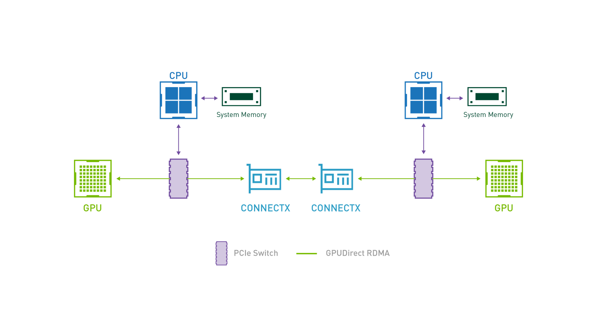
GPUDirect RDMA provides direct communication between NVIDIA GPUs in remote systems.
It bypasses the system CPUs and eliminates the required buffer copies of data via the system memory, resulting in a significant performance boost.
Use Case Topology
The following topology describes VM instances with hardware accelerated bond interface and A100 GPU located on remote compute nodes, and running GPUDirect RDMA workload over Geneve overlay tenant network.
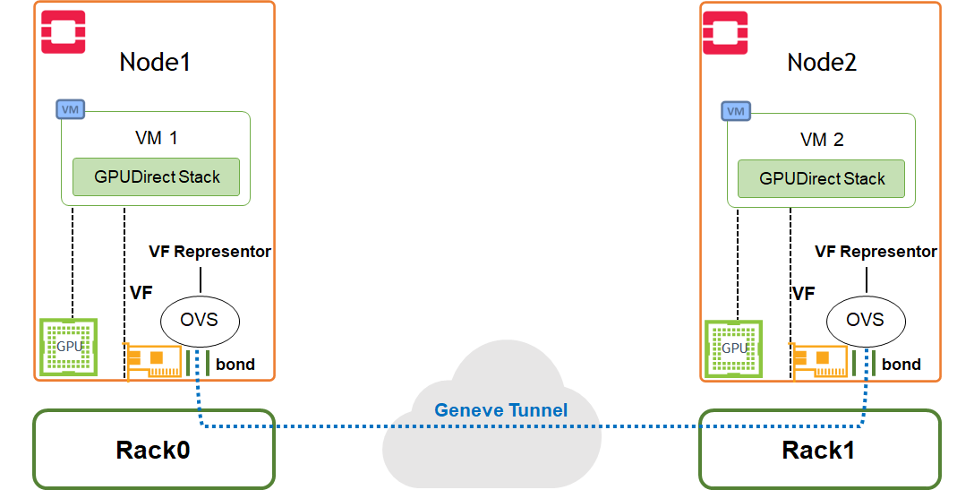
Image description: GPUDirect RDMA Acceleration Use Case Topology
Use Case Benchmarks
GPUDirect-enabled RDMA Bandwidth
Note
The performance results listed in this document are indicative and should not be considered as formal performance targets for NVIDIA products.
Notes
-
Performing an optimal GPUDirect RDMA Benchmark test requires a server with PCIe Bridges. The network adapter and GPU used in this test should be located under the same PCIe Bridge device and associated with the same CPU NUMA node.
-
The "lspci -tv" command can be used to display the device hierarchy and verify that the adapter/GPU PCI devices are hosted under the same PCIe Bridge.
-
"lspci -vvv -s <PCI_Device_ID>" can be used to identify the NUMA node associated with the adapter/GPU PCI devices.
-
-
GPUDirect RDMA in a virtual environment requires enablement of ATS (Address Translation Services) on the Network adapter, as well as ACS (Access Control Services) on the PCIe Bridge and server BIOS.
-
In the servers used for this test, the Network-RDMA device (ConnectX-6Dx) and GPU device (PCIe A100) share NUMA Node 0, and are connected under the same PCIe Bridge device.
-
For the GPUDirect RDMA benchmark test described in this section, the virtual instance guest OS must include CUDA and MLNX_OFED v5.6, or later.
-
Some of the configurations applied in this section are not persistent, and therefore, have to be reapplied after a server/instance reboot.
-
NVIDIA Multi-Instance GPU (MIG) must be disabled for this test.
-
On AMD-based servers, it is required to set the network adapter ATC registry in order to optimize the GPUDirect RDMA Benchmark results.
-
Prepare the setup for running a GPUDirect RDMA test over a virtualized environment by applying the following steps on both compute nodes:
-
-
Delete any existing instance on the compute nodes.
-
Install the mstflint package.
# apt install mstflint -
Locate the network adapter PCI ID, and enable ATS in firmware.
# lspci | grep -i nox 3f:00.0 Ethernet controller: Mellanox Technologies MT2892 Family [ConnectX-6 Dx] 3f:00.1 Ethernet controller: Mellanox Technologies MT2892 Family [ConnectX-6 Dx] # mstconfig -d 3f:00.0 set ATS_ENABLED=true -
Reboot the compute nodes to apply the new firmware configuration.
-
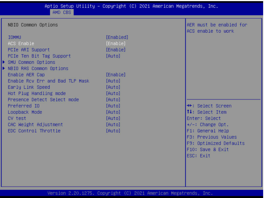
Stop the server during the boot process in the BIOS menu, and make sure that ACS is enabled.
-
-
Image description: BIOS ACS Configuration Example
-
-
-
Once the server is rebooted, verify that the adapter firmware parameters have been applied.
# mstconfig -d 3f:00.0 q | grep "ATS_ENABLED"
  ATS_ENABLED                         True(1)
-
-
-
-
-
Enable ACS on the PCIe Bridge device that is hosting the adapter and GPU.
-
In many server architectures, there are multiple chained PCIe Bridge devices serving a bulk of PCIe slots. It may be possible that the adapter and GPU will be connected to different sub devices in this PCIe bridge chain.
-
The provided command will enable ACS on ALL PCIe Bridge devices in the system.
-
This step is not persistent, and has to be re-applied every time the server is rebooted while there are no virtual instances running.
# for BDF in `lspci -d "*:*:*" | awk '{print $1}'`; do setpci -v -s ${BDF} ECAP_ACS+0x6.w=0x5D ; done; -
-
Verify that the ACS Direct Translation was enabled on the PCIe Bridge device hosting the adapter and GPU.
# lspci -s <PCIe_Bridge_Device_ID> -vvv | grep ACSCtl ACSCtl: SrcValid+ TransBlk- ReqRedir+ CmpltRedir+ UpstreamFwd+ EgressCtrl- DirectTrans+ -
On servers with AMD CPU, set the network adapter ATC Registry.
# mstmcra 3f:00.0 0xa1334.16:5 24 -
To verify that it was set:
# mstmcra 3f:00.0 0xa1334.16:5
0x00000018
-
-
-
Create a new flavor with A100 GPU alias and ratio:
$ openstack flavor create m100.gpu --ram 8192 --disk 20 --vcpus 10 $ openstack flavor set m100.gpu --property "pci_passthrough:alias"="a100-gpu:1" $ openstack flavor set m100.gpu --property hw:cpu_policy=dedicated $ openstack flavor set m100.gpu --property hw:mem_page_size=large -
Create 2 VM instances, as instructed in previous steps.
-
The same networks and ports created in the previous use-case can be used in this use-case as well.
-
Use the newly created flavor.
-
Use a stateless security group for this use case.
-
The VM image used for this test is based on Ubuntu 22.04, and includes the following software: CUDA v11.7, MLNX_OFED v5.7-1.0.2.0, perftest tool set compiled with CUDA support. The VM image was built using a disk-image-builder tool. The following article can be used as a reference: How-to: Create OpenStack Cloud Image with NVIDIA GPU and Network Drivers.
-
-
Login to both VM instances, and verify that the GPU and SR-IOV VF devices are listed.
# lspci 00:00.0 Host bridge: Intel Corporation 440FX - 82441FX PMC [Natoma] (rev 02) 00:01.0 ISA bridge: Intel Corporation 82371SB PIIX3 ISA [Natoma/Triton II] 00:01.1 IDE interface: Intel Corporation 82371SB PIIX3 IDE [Natoma/Triton II] 00:01.2 USB controller: Intel Corporation 82371SB PIIX3 USB [Natoma/Triton II] (rev 01) 00:01.3 Bridge: Intel Corporation 82371AB/EB/MB PIIX4 ACPI (rev 03) 00:02.0 VGA compatible controller: Red Hat, Inc. Virtio GPU (rev 01) 00:03.0 Ethernet controller: Red Hat, Inc. Virtio network device 00:04.0 SCSI storage controller: Red Hat, Inc. Virtio block device 00:05.0 Ethernet controller: Mellanox Technologies ConnectX Family mlx5Gen Virtual Function 00:06.0 3D controller: NVIDIA Corporation GA100 [A100 PCIe 40GB] (rev a1) 00:07.0 Unclassified device [00ff]: Red Hat, Inc. Virtio memory balloon 00:08.0 Unclassified device [00ff]: Red Hat, Inc. Virtio RNG -
On both VMs, load the nvidia-peermem module:
# modprobe nvidia-peermem # lsmod | grep -i peermem nvidia_peermem 16384 0 ib_core 430080 9 rdma_cm,ib_ipoib,nvidia_peermem,iw_cm,ib_umad,rdma_ucm,ib_uverbs,mlx5_ib,ib_cm nvidia 40816640 18 nvidia_uvm,nvidia_peermem,nvidia_modeset -
On both VMs, disable MIG, enable the GPU device persistence mode, and lock the GPU clock on the maximum allowed speed.
-
Apply the following settings only when the bandwidth test result is not satisfactory.
-
MIG disable is required for A100 GPUs
-
Do NOT set a value higher than allowed per specific GPU device.
-
"nvidia-smi -i <device id> -q -d clock" command can be used to identify the Max Allowed Clock of a device.
-
For the A100 device we used in this test, the Max Allowed Clock is 1410 MHz.
-
# nvidia-smi -i 0 -mig 0 Disabled MIG Mode for GPU 00000000:00:06.0 All done. # nvidia-smi -i 0 -pm 1 Persistence mode is already Enabled for GPU 00000000:00:06.0. All done. # nvidia-smi -i 0 -lgc 1410 GPU clocks set to "(gpuClkMin 1410, gpuClkMax 1410)" for GPU 00000000:00:06.0 All done. -
-
Start the GPUDirect RDMA ib_write_bw server on one of the virtual instances:
-
ib_write_bw is provided as part of the perftest tool set compiled with CUDA support on the VM image with CUDA and MLNX_OFED
-
It is possible to run a network-based test without GPUDirect RDMA by omitting the "use_cuda" flag
root@vm2:/home/ubuntu# ib_write_bw -F -q 4096 --tclass=96 --report_gbits -R --use_cuda=0 ************************************ * Waiting for client to connect... * ************************************ -
-
Start the GPUDirect ib_write_bw client on the second instance by specifying the IP of the remote instance and a test packet size:
root@vm1:/home/ubuntu# ib_write_bw -F -q 4096 --tclass=96 --report_gbits -R -D 30 33.33.33.17 --use_cuda=0 initializing CUDA Listing all CUDA devices in system: CUDA device 0: PCIe address is 00:06 Picking device No. 0 [pid = 2471, dev = 0] device name = [NVIDIA A100-PCIE-40GB] creating CUDA Ctx making it the current CUDA Ctx cuMemAlloc() of a 536870912 bytes GPU buffer allocated GPU buffer address at 00007f8aa0000000 pointer=0x7f8aa0000000 . . . remote address: LID 0000 QPN 0x2ccd PSN 0xface62 GID: 00:00:00:00:00:00:00:00:00:00:255:255:33:33:33:17 remote address: LID 0000 QPN 0x2cce PSN 0x61e9a4 GID: 00:00:00:00:00:00:00:00:00:00:255:255:33:33:33:17 remote address: LID 0000 QPN 0x2ccf PSN 0x7d428 GID: 00:00:00:00:00:00:00:00:00:00:255:255:33:33:33:17 remote address: LID 0000 QPN 0x2cd0 PSN 0x3904a8 GID: 00:00:00:00:00:00:00:00:00:00:255:255:33:33:33:17 remote address: LID 0000 QPN 0x2cd1 PSN 0x6b878c GID: 00:00:00:00:00:00:00:00:00:00:255:255:33:33:33:17 --------------------------------------------------------------------------------------- #bytes #iterations BW peak[Gb/sec] BW average[Gb/sec] MsgRate[Mpps] 65536 5681224 0.00 186.16 0.355076 --------------------------------------------------------------------------------------- deallocating RX GPU buffer 00007f8aa0000000 destroying current CUDA Ctx-
The test is demonstrating an average bandwidth of 186Gbps for a packet size of 32KB over a leaf-spine fabric with Geneve encapsulation
-
The test above was executed on AMD servers with PCIe Gen4 support, that are optimized for GPUDirect RDMA.
-
Similar result was achieved for an RDMA bandwidth test without GPUDirect on the same servers.
-
Authors
|
|
Itai Levy
Over the past few years, Itai Levy has worked as a Solutions Architect and member of the NVIDIA Networking “Solutions Labs” team. Itai designs and executes cutting-edge solutions around Cloud Computing, Software-Defined Networking, Storage and Security. His main areas of expertise include NVIDIA BlueField Data Processing Unit (DPU) solutions and accelerated K8s/OpenStack platforms. |

Last updated: