Created on Oct 5, 2020
Scope
This document describes how to configure NVMe-oF RoCE Datastores in VMware vSphere 7.0 with Pavilion Hyperparallel Flash Array system over NVIDIA Mellanox end-to-end 100 Gb/s Ethernet solution.
Abbreviations and Acronyms
|
Term |
Definition |
Term |
Definition |
|---|---|---|---|
|
DAC |
Direct Attached Cable |
RDMA |
Remote Direct Memory Access |
|
DHCP |
Dynamic Host Configuration Protocol |
RoCE |
RDMA over Converged Ethernet |
|
HFA |
Hyperparallel Flash Array |
QSG |
Quick Start Guide |
|
NOS |
Network Operation System |
vDS |
vSphere Distributed Switch |
|
NVMe |
Non-Volatile Memory express |
VM |
Virtual Machine |
|
NVMe-oF RoCE |
NVMe over Fabrics over RoCE |
|
|
Introduction
vSphere 7.0 adds a new feature which massively increase performance of I/O bound VMs such as databases or business intelligence - the NVMe over Fabrics (NVMe-oF).
With NVMe-oF SW it is now possible to virtualize I/O intensive workloads that needed to be run on bare metal before.
NVMe-oF can also increase the performance of more traditional VMs, allowing more of them to be run on the same hardware.
The Pavilion HFA is one of the first NVMe-oF all-flash arrays to be certified by VMware for use with vSphere 7.0.
In the document we will provide how to configure NVMe-oF RoCE Datastores located on Pavilion HFA in VMware vSphere 7.0 over NVIDIA Mellanox end-to-end 100 Gb/s Ethernet solution.
HCI Bench v2.5.1 VDBENCH will be used for benchmarks to show performance improvements between RDMA based NVME-oF and iSCSI protocols by using same hardware..
References
Solution Architecture
Key Components and Technologies
-
NVMe-oF over RoCE support for VMware
NVMe-oF (aka NVMe over Fabrics) is a protocol specification designed to connect hosts to storage across a network fabric using the NVMe protocol.
VMware added support for shared NVMe storage using NVMe-oF. For external connectivity, NVMe over RDMA is supported in vSphere 7.0. ESXi hosts can use RDMA over Converged Ethernet v2 (RoCE v2). -
NVIDIA Cumulus Linux
Cumulus Linux is the only open network OS that allows you to affordably build and efficiently operate your network like the world’s largest data center operators, unlocking web-scale networking for businesses of all sizes. -
NVIDIA MELLANOX CONNECTX SMARTNICS
The industry-leading ConnectX® family of intelligent data-center network adapters offers the broadest and most advanced hardware offloads. NVIDIA® Ethernet adapters enable the highest ROI and lowest TCO for hyperscale, public and private clouds, storage, machine learning, AI, big data and telco platforms, with Ethernet data rates of 10GbE, 25GbE, 40GbE, 50GbE, 100GbE and 200GbE per port. -
NVIDIA Mellanox Spectrum Open Ethernet Switches
The Mellanox Spectrum® switch family provides the most efficient network solution for the ever-increasing performance demands of data center applications. The Spectrum product family includes a broad portfolio of Top-of-Rack (TOR) and aggregation switches that range from 16 to 128 physical ports, with Ethernet data rates of 1GbE, 10GbE, 25GbE, 40GbE, 50GbE, 100GbE and 200GbE per port. Spectrum Ethernet switches are ideal to build cost-effective and scalable data center network fabrics that can scale from a few nodes to tens-of-thousands of nodes. -
NVIDIA Mellanox LinkX Ethernet Cables and Transceivers
Mellanox LinkX® cables and transceivers make 100Gb/s deployments as easy and as universal as 10Gb/s links. Because Mellanox offers one of industry’s broadest portfolio of 10, 25, 40, 50,100 and 200Gb/s Direct Attach Copper cables (DACs), Copper Splitter cables, Active Optical Cables (AOCs) and Transceivers, every data center reach from 0.5m to 10km is supported. To maximize system performance, Mellanox tests every product in an end-to-end environment ensuring a Bit Error Rate of less than 1e-15. A BER of 1e-15 is 1000x better than many competitors. -
Pavilion Hyperparallel Flash Array
The Pavilion Hyperparallel Flash Array is one of the industry’s most capable and highest performant solution for delivering real time performance at scale within reach of all.
Logical Design
Software Stack Components
This guide assumes the following software and drivers are installed:
-
VMware ESXi 7.0.1, build 16850804
-
vCenter 7.0.1, build 17005016
-
Distributed Switch 7.0.0
-
VM Guest OS: Ubuntu 18.04.3
-
VM Hardware Version: 18
As a Network Operational System (NOS) we will use:
-
NVIDIA Cumulus Linux: 4.1.1
As a storage system we will use a Pavilion Hyper Parallel Flash Array (HFA) with NVMe over RoCE protocol.
-
Pavilion Data System: 2.3.3.0_11378
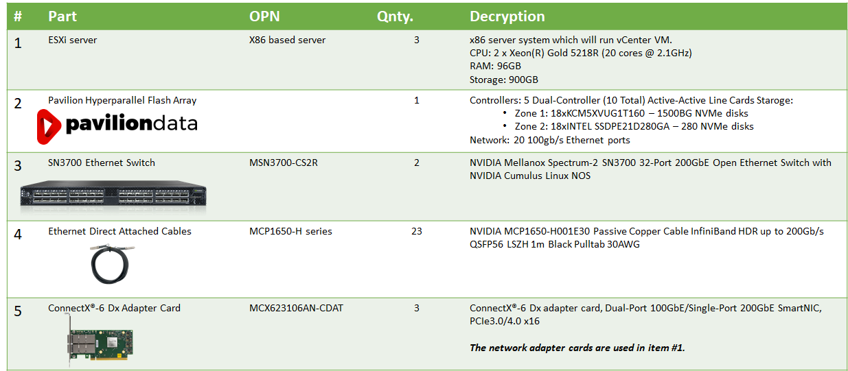
Bill of Materials
The following hardware setup is utilized in the vSphere environment described in this guide:
Deployment and Configuration
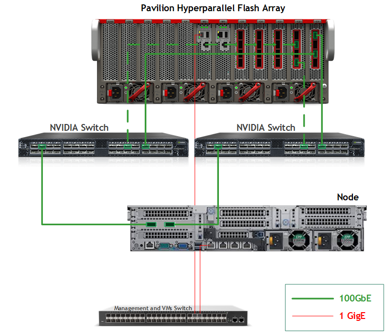
Wiring
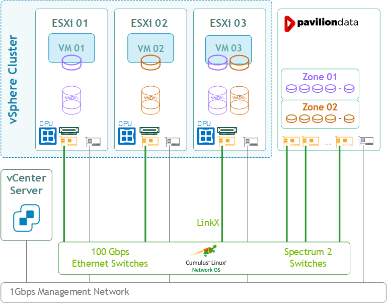
This document covers highly available VMware vSphere cluster deployment.
Network
Prerequisites
-
Switch OS
NVIDIA Cumulus Linux 4.1.1 -
Network adapter
ConnectX-5 and above, supporting RoCE. -
A NVMe-oF requires:
RDMA compatible Ethernet NICs (RNICs) in the ESXi servers with MTU 9000 (Jumbo ethernet frame). -
Management Network
DHCP and DNS services are required. The components Installation and configuration are not covered in this guide.
Network Configuration
This table provides details of the ESXi server, switches and storage system names and their network configuration.
The 2 port groups (NVMe-RoCE-A and NVMe-RoCE-B) are required to support Active/Passive NVMe-oF connectivity which will act as multi-path to storage system.
In the our environment Pavilion storage came in configuration of 5 Dual-Controllers with 2 IO ports each (20 ports in total).
|
Server |
Server Name |
IP and NICs |
|
|---|---|---|---|
|
High-Speed Ethernet Network |
Management Network 10.236.0.0 |
||
|
ESXi-01 |
qavmw-235 |
vmk1: 172.101.10.35 (NVMe-RoCE-A) vmk2: 172.101.20.35 (NVMe-RoCE-B) vmk3: 172.101.2.135 (vMotion-DPG) |
vmk0: 10.236.235.1 From DHCP (reserved) |
|
ESXi-02 |
qavmw-237 |
vmk1: 172.101.10.37 (NVMe-RoCE-A) vmk2: 172.101.20.37 (NVMe-RoCE-B) vmk3: 172.101.2.37 (vMotion-DPG) |
vmk0: 10.236.237.1 From DHCP (reserved) |
|
ESXi-03 |
qavmw-239 |
vmk1: 172.101.10.39 (NVMe-RoCE-A) vmk2: 172.101.20.39 (NVMe-RoCE-B) vmk3: 172.101.2.39 (vMotion-DPG) |
vmk0: 10.236.239.1 From DHCP (reserved) |
|
Switch |
sw-qa-sx-053 |
|
10.7.86.53 |
|
Storage |
qa-pavilion10 |
Dual-Controller - C1 100g-1/1: 172.10.10.106 (Controller11) 100g-1/2: 172.10.20.106 (Controller11) 100g-1/3: 172.10.10.101 (Controller1) 100g-1/4: 172.10.20.101 (Controller1) Dual-Controller - C2 100g-2/1: 172.10.10.107 (Controller12) 100g-2/2: 172.10.20.107 (Controller12) 100g-2/3: 172.10.10.102 (Controller2) 100g-2/4: 172.10.20.102 (Controller2) . . . Dual-Controller - C5 100g-5/1: 172.10.10.110 (Controller15) 100g-5/2: 172.10.20.110 (Controller15) 100g-5/3: 172.10.10.105 (Controller5) 100g-5/4: 172.10.20.105 (Controller5) |
10.7.87.10 |
Network Switch Configuration for RoCE Transport
NVIDIA Cumulus Linux Network OS
RoCE transport is utilized to accelerate NVMe networking. To get the highest possible results we will configure our network to be lossless.
Run the following commands on both Leaf switches to configure a lossless networks and for NVIDIA Cumulus version 4.1.1 and above:
Switch console
net add interface swp13-32 storage-optimized pfc
net commit
On Left Leaf switch add VLAN 10 to ports 13-32 on NVIDIA Cumulus Linux Network OS by running the following commands:
Switch console
net add interface swp13-32 bridge trunk 10
net add interface swp13-32 bridge trunk vlans 10
net commit
On Right Leaf switch add VLAN 20 to ports 13-32 on NVIDIA Cumulus Linux Network OS by running the following commands:
Switch console
net add interface swp13-32 bridge trunk 20
net add interface swp13-32 bridge trunk vlans 20
net commit
Storage
Prerequisites
To set up an Pavilion HFA environment, the following is required:
-
Connection to console and management interfaces.
-
Installer privileges: The installation requires administrator privileges on the target machine.
-
High speed network connectivity.
Configuring NVMe over RoCE using GUI
Below is a detailed step-by-step description of a Pavilion Controller configuration for NVMe over RoCE using GUI.
-
Login to the Pavilion GUI.

-
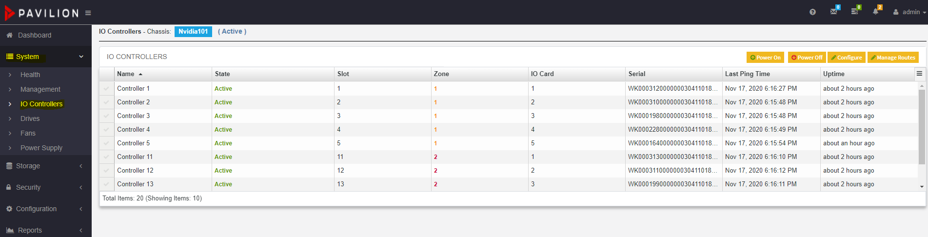
Navigate to System>IO Controller.
-
Configure controllers 1 and 2 for NVMe Over RoCE.
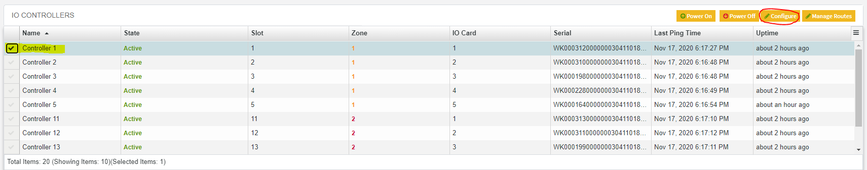
All controllers by default are configured for NVMe Over RoCE.
To change protocol type for a controller, select the controller and click on Configure button displayed at the top-right corner of the page. -
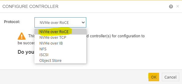
Select the Protocol as NVMe over RoCE and click OK.
-
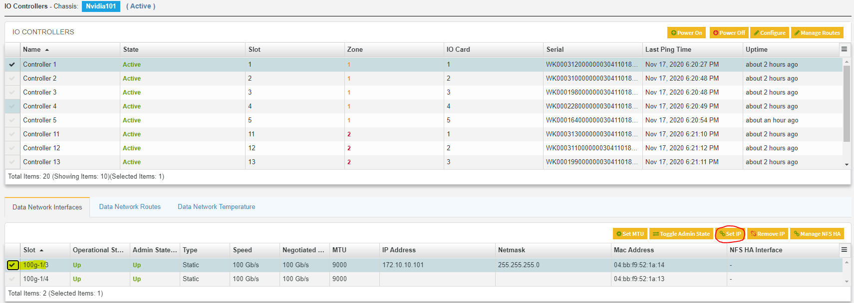
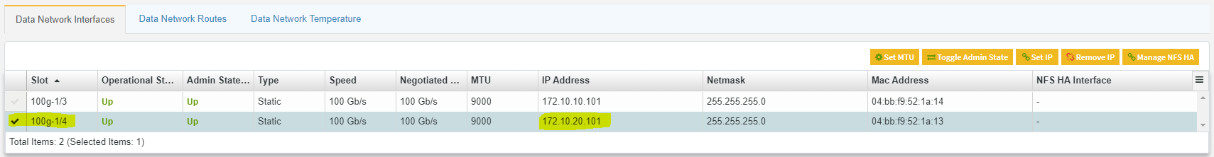
To assign a DataPort IP address for Pavilion controller.
Select any available DataPort slot for controller 1 and click Set IP.
-
On the Set DataPort IP dialog box set IP address and Netmask.
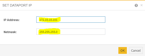
-
Repeat steps 5 and 6 to assign a DataPort IP address for second DataPort ( Sample: 172.10.20.101).
-
Repeat the above steps to configure protocol and assign IP address for all the controllers.
Creating Datastore Volumes on the Pavilion HFA
Before creating volumes, ensure that controllers are configured for RoCE and media groups are created.
To create Datastore volumes:
-
Navigate to Storage>Volumes>Create Volume.
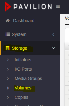
-
On the Volumes page, click Create button to create a volume.

-
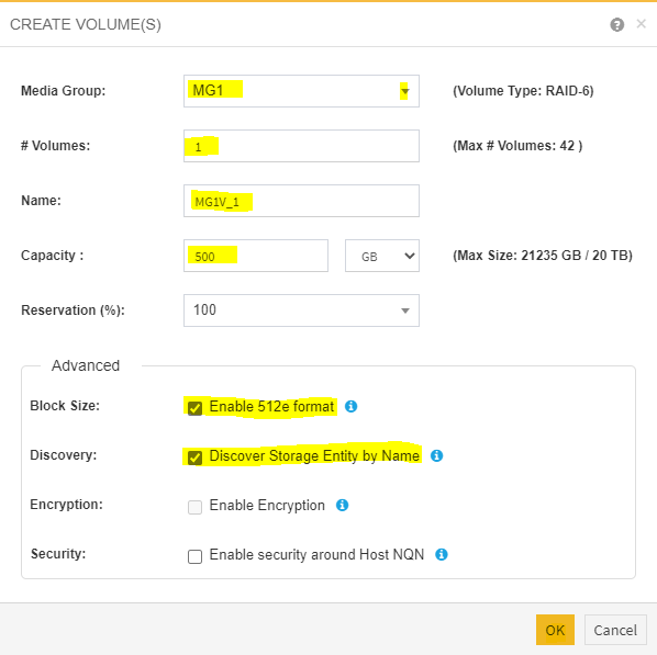
Fill in the details in the Create Volumes page.
Check the Enable 512e format and Discover storage entity by name checkbox. As, VMFS requires 512-byte emulated sectors to function
-
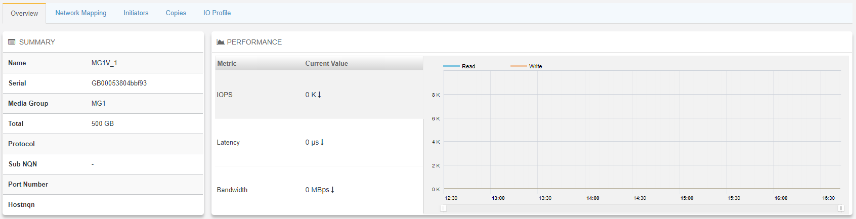
Subsequently, new volume <MG1V-1> is created.

Assigning the Datastore Volumes for High Availability
Once the volume is created, it needs to be assigned to a pair of controllers to serve as active and passive controllers for High Availability.
-
Select the volume just created and use the Pavilion GUI navigate to: Storage>Volumes>Assign.

-
On the Assign Volumes dialog box, tick the boxes.
Make a note of the two IP addresses present (one from each controller), as these are be required to configure the ESXi server.
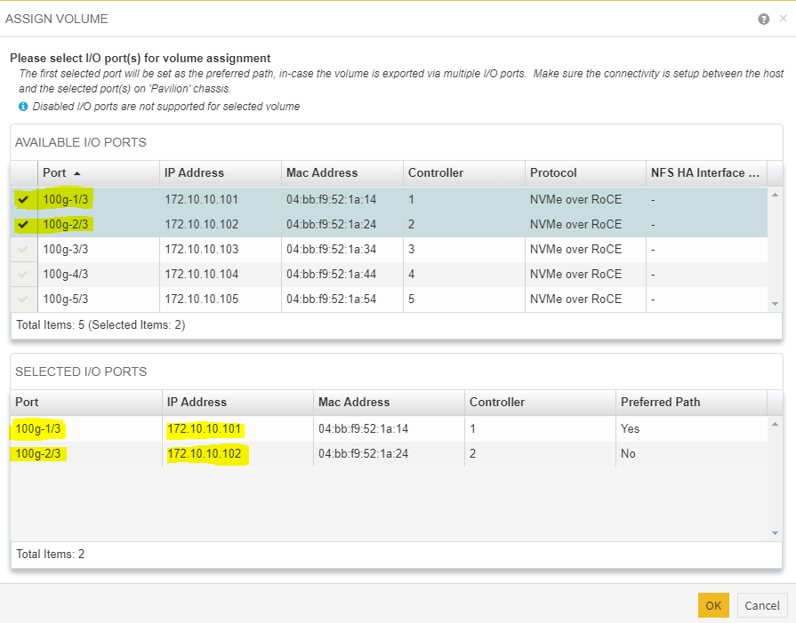
-
The volume is assigned, and volume state is changed from unassigned to online, see image below:

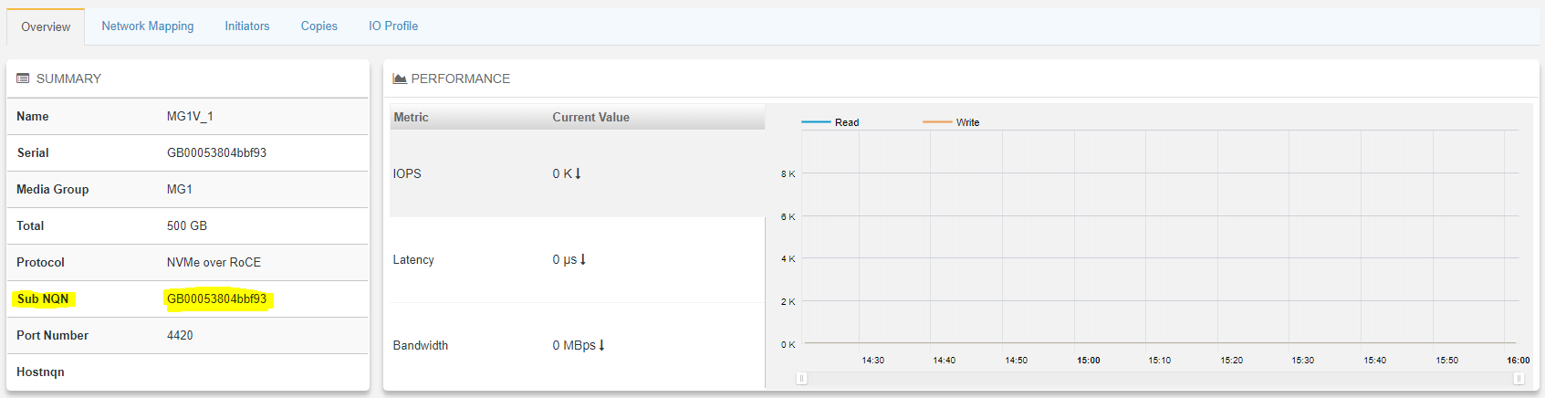
Save the Sub NQN.
-
At this point the volume will be visible on the network via two different IPs and the ESXi servers can be set up.
ESXi Host Configuration
Prerequisites
-
VMware vSphere ESXi 7.0.0 or later.
-
vCenter 7.0.0 or later.
-
Installer privileges: The installation requires administrator privileges on the target machine.
-
Connection to ESXi host management interface.
-
High speed network connectivity.
Firstly, we need to create a vSphere Distributed Switch (vDS) with 2 distributed port groups with one Active and Standby uplink.
Creating a Distributed Switch for Storage Traffic
To create a new vDS:
-
Launch the vSphere Web Client and connect to a vCenter Server instance.
-
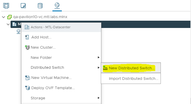
On the vSphere Web Client home screen, select the vCenter object from the list on the left.
Hover over the Distributed Switches from the Inventory Lists area, then click New Distributed Switch (see image below) to launch the New vDS creation wizard:
-
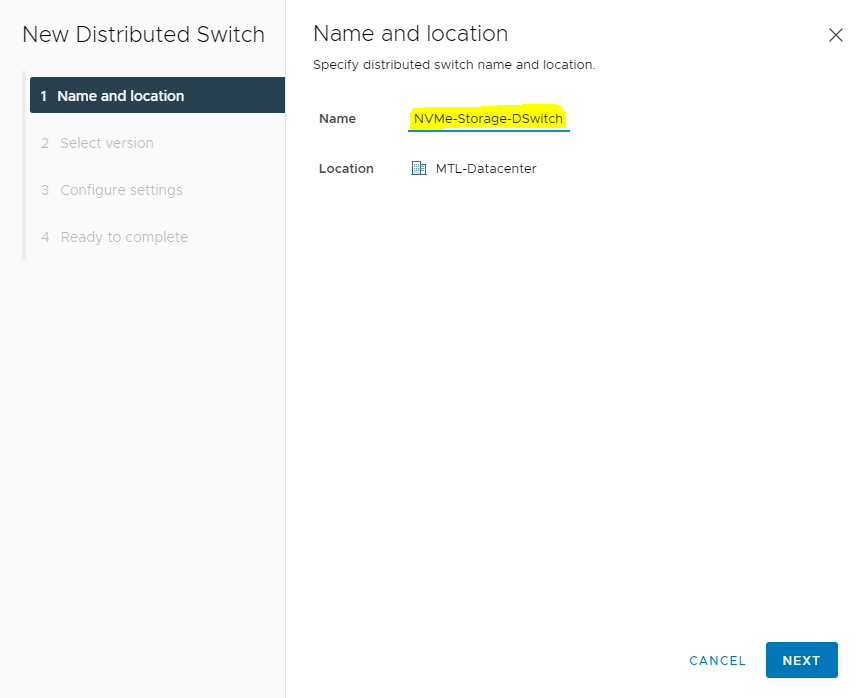
Provide a name for the new distributed switch and select the location within the vCenter inventory where you would like to store the new vDS (a data center object or a folder).
Click NEXT.
-
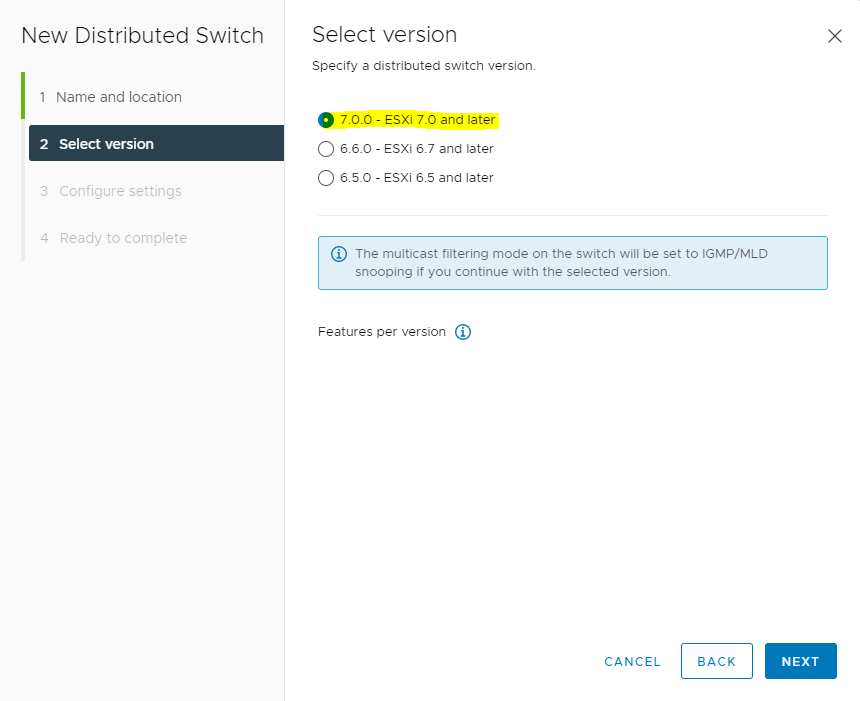
Select the version of the vDS to create.
-
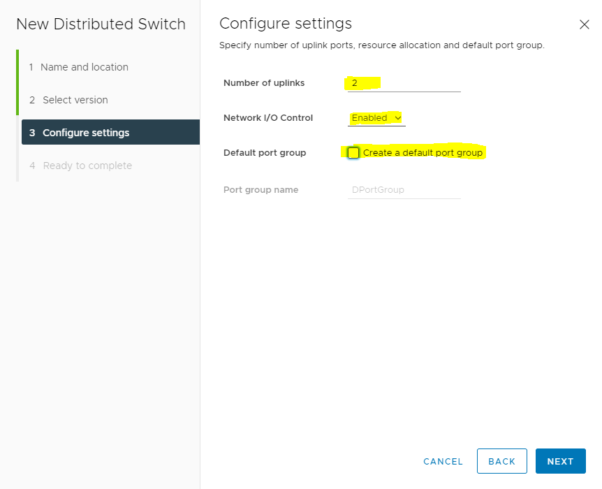
Specify the number of uplink ports as 2, uncheck the Create a default port group box and give a name to that group.
-
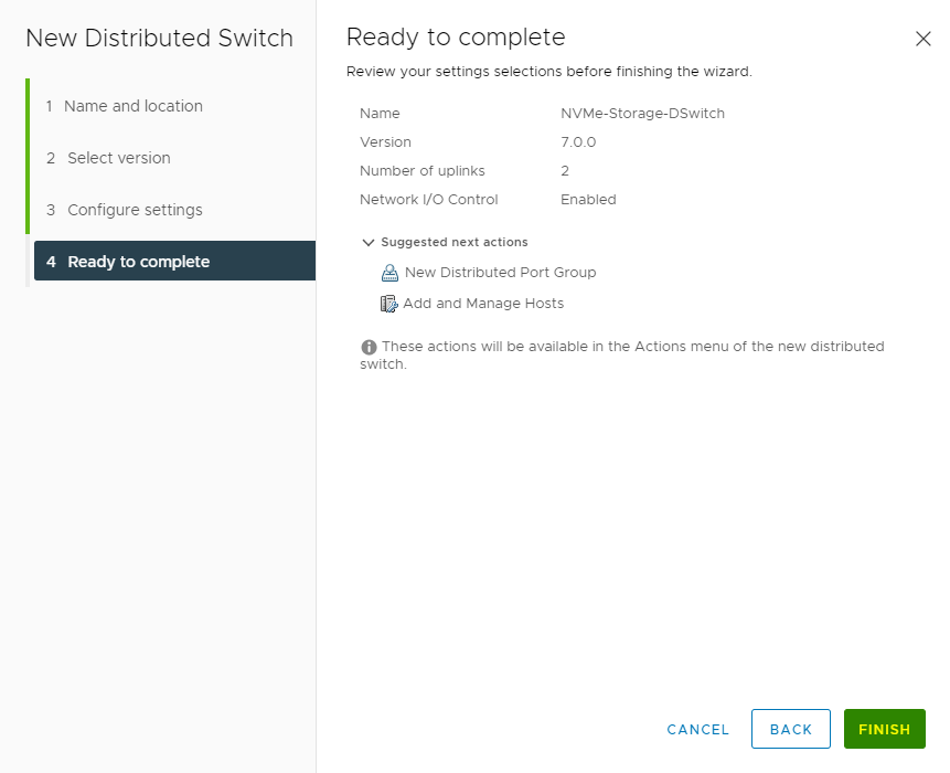
Click Finish.
-
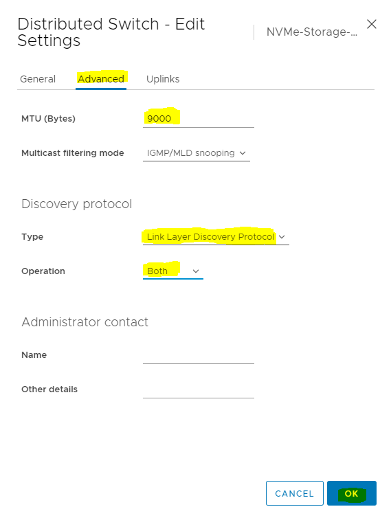
Set MTU for the newly created distributed switch.
Select the switch created and go to Actions and click Edit Settings.
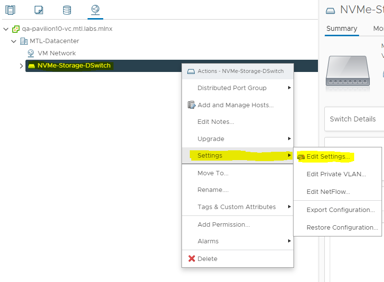
In the Storage-DSwitch-Edit Settings dialog box set MTU to 9000, Discovery protocol to Link Layer Discovery Protocol and Operation to Both.
Adding Hosts to vDS
To add an ESXi host to an existing vDS:
-
Launch the vSphere Web Client, and connect to a vCenter Server instance.
-
Navigate to the list of distributed switches.
-
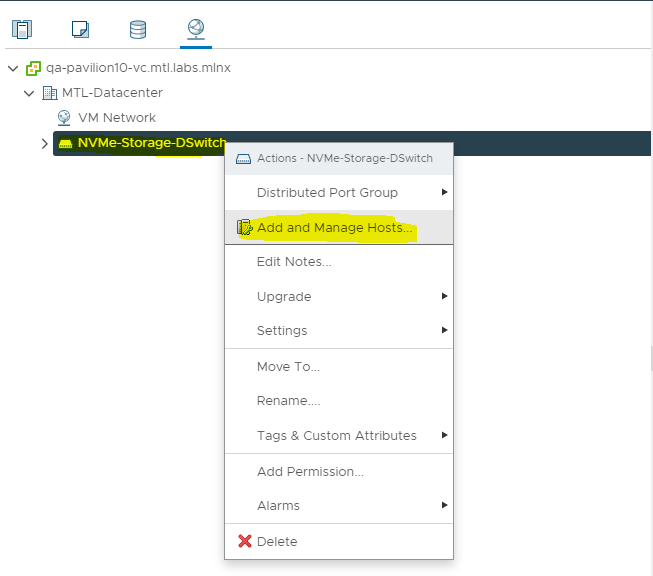
Right-click the new distributed switch in the list of objects and select Add and Manage Hosts from the Actions menu.
-
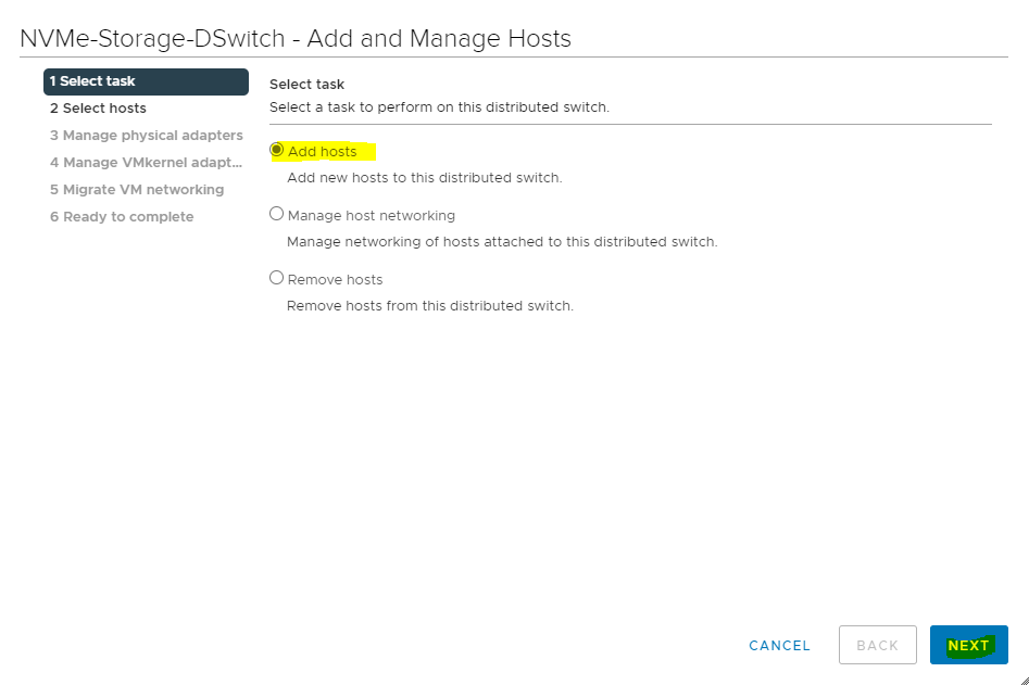
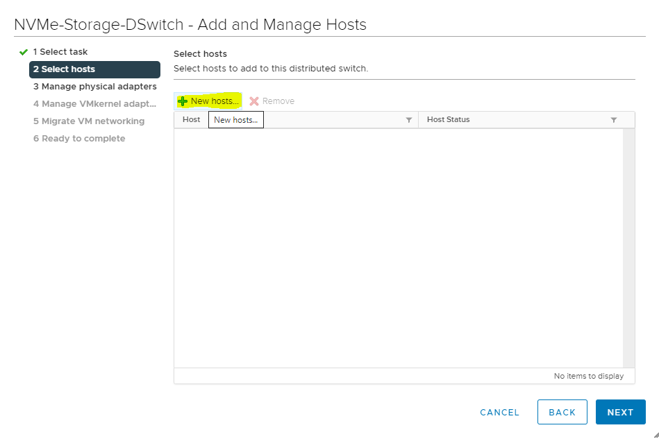
Select the Add hosts button and click Next.
-
Click the New hosts green plus icon to add an ESXi host. This opens the Select New Host dialog box.
-
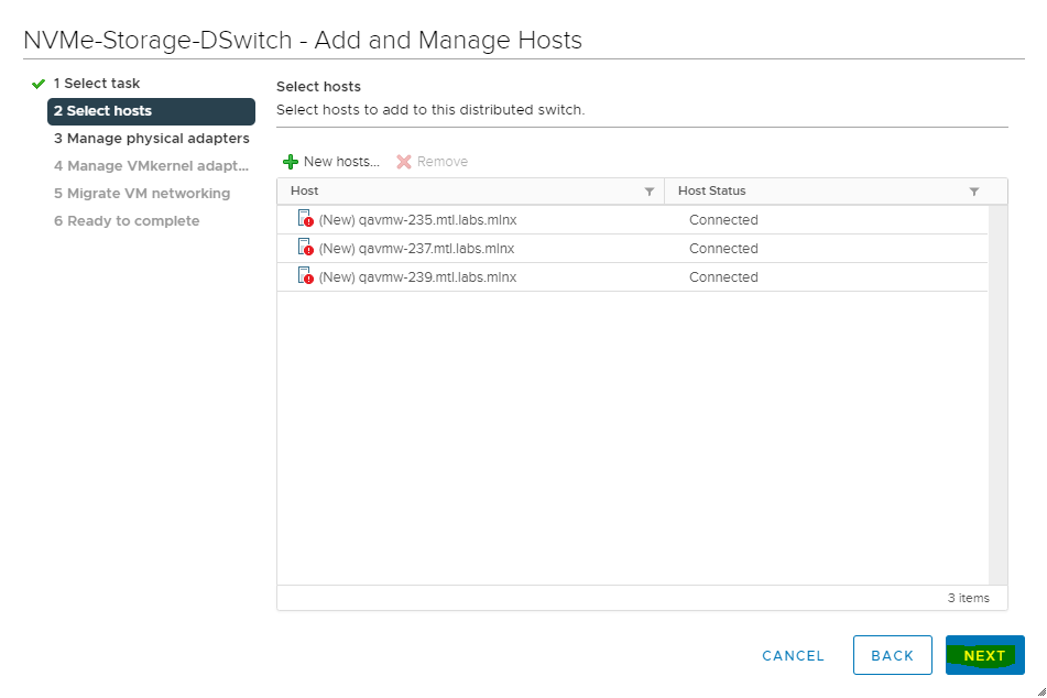
From the list of new hosts, tick the boxes with the names of each ESXi host you want to add to the vDS.
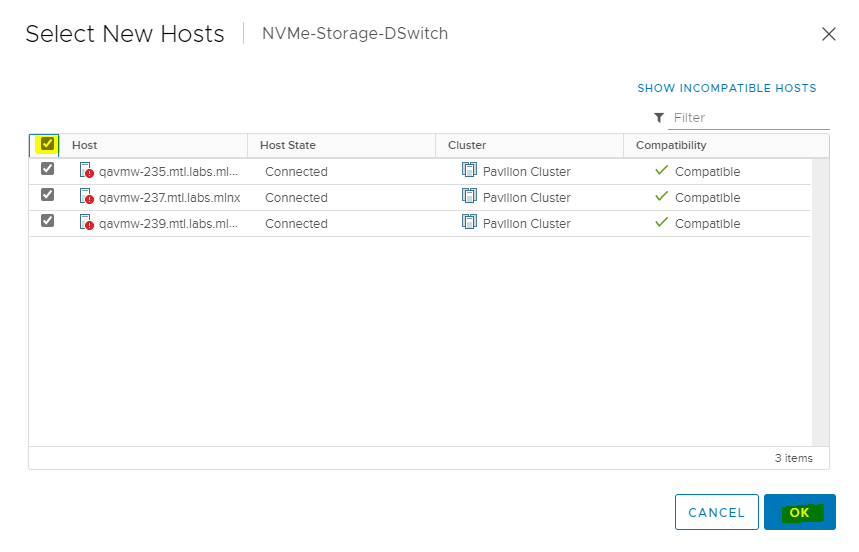
Click OK when you are done, and then click NEXT to continue.
-
In the next Manage physical adapters screen Configure vmnic6 in a ESXi host as an Uplink 1 for vDS.
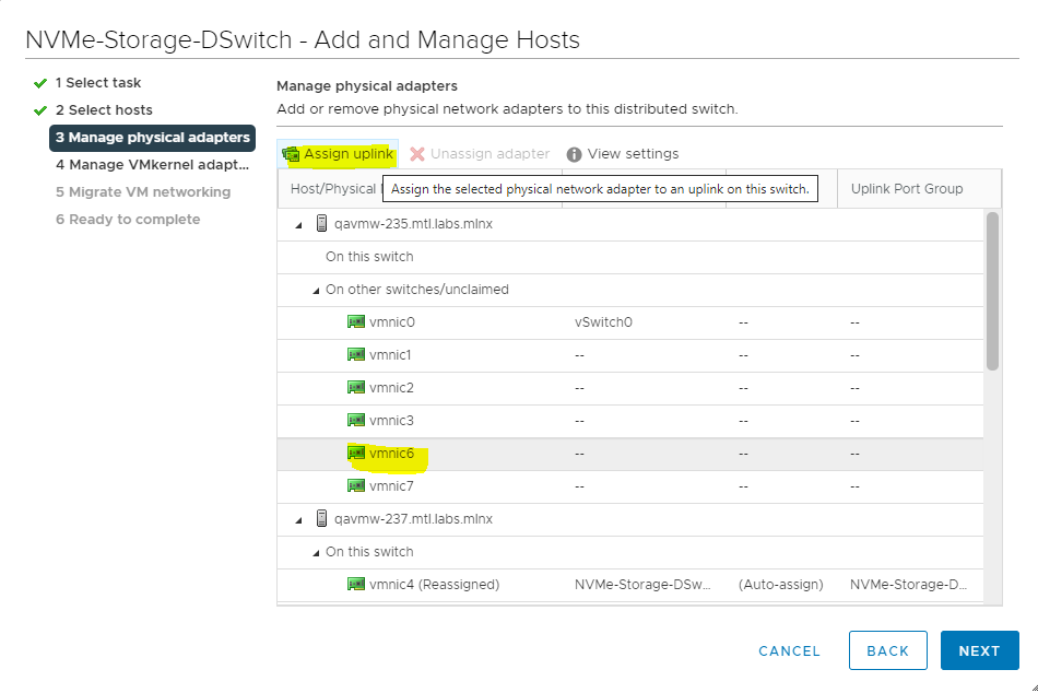
-
On the Select an Uplink dialog box, select the Uplink. Make sure to check the Apply this uplink assignment to the rest of the hosts checkbox.
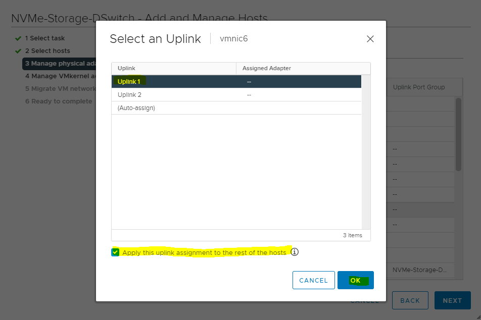
-
Repeat steps 7 and 8 to Configure vmnic7 in a ESXi host as an Uplink 2 for vDS and click OK.
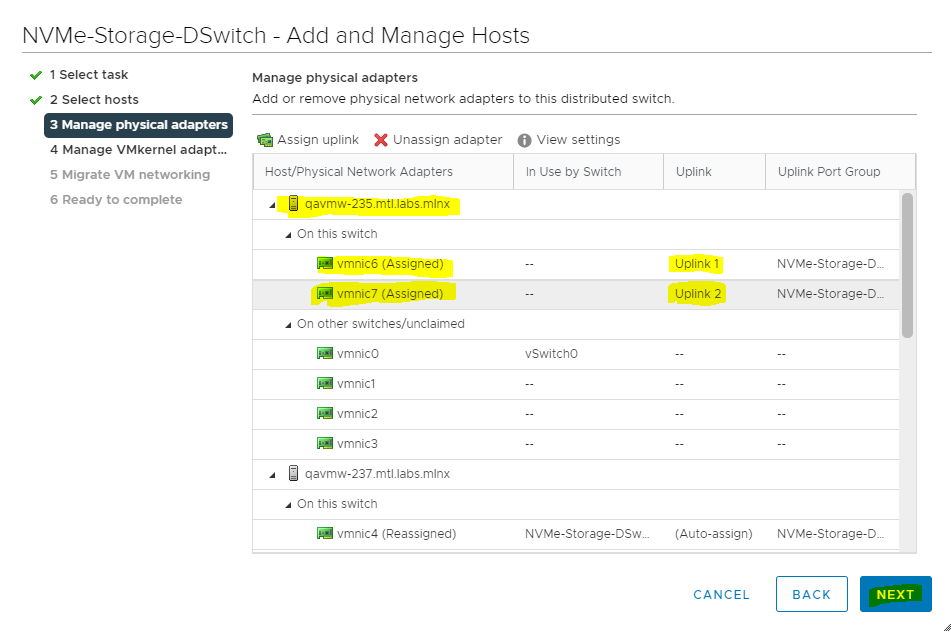
-
Verify NICs are assigned to Uplinks and click NEXT.
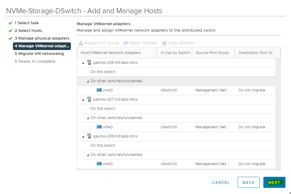
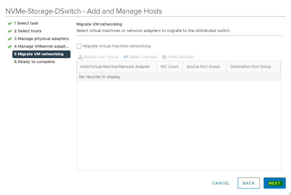
-
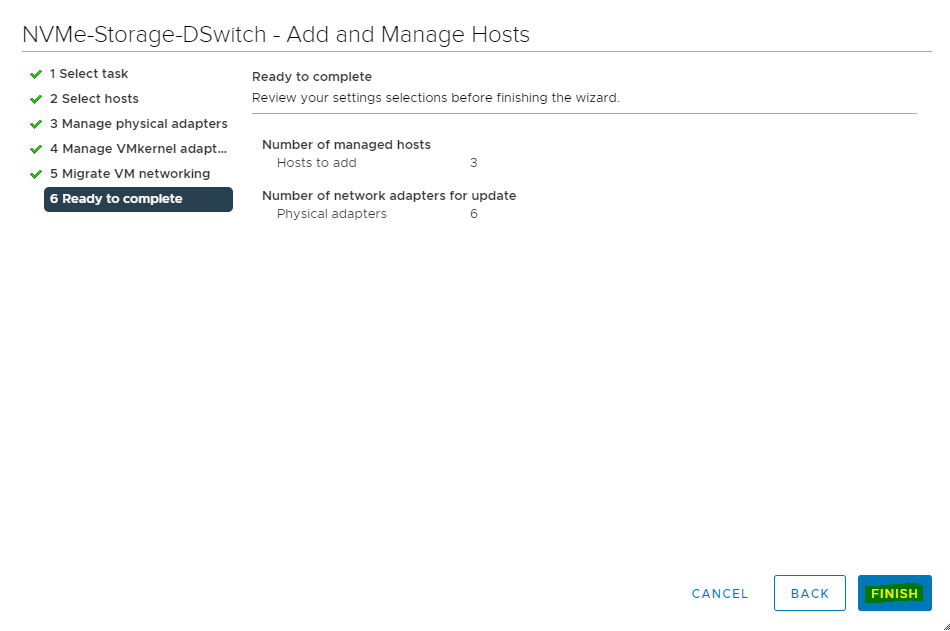
In the next Manage VMkernel adapters and Migrate VM networking screen click NEXT to continue.
-
Click FINISH.
Creating Distributed Port Groups for Storage Traffic
This section lists the steps required to create 2 distributed port groups with one Active and Standby uplink.
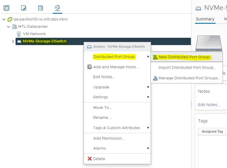
-
Adding VMkernel Adapters for Distributed Port GroupsRight click on Distributed switch and select Distributed Port Group>New Distributed Port Group.
-
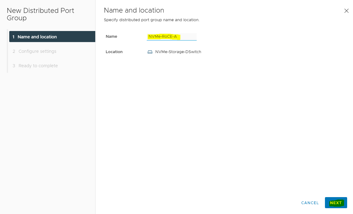
On the New Distributed Port Group dialog box, enter Name as <NVMe-RoCE-A>and click on Next.
-
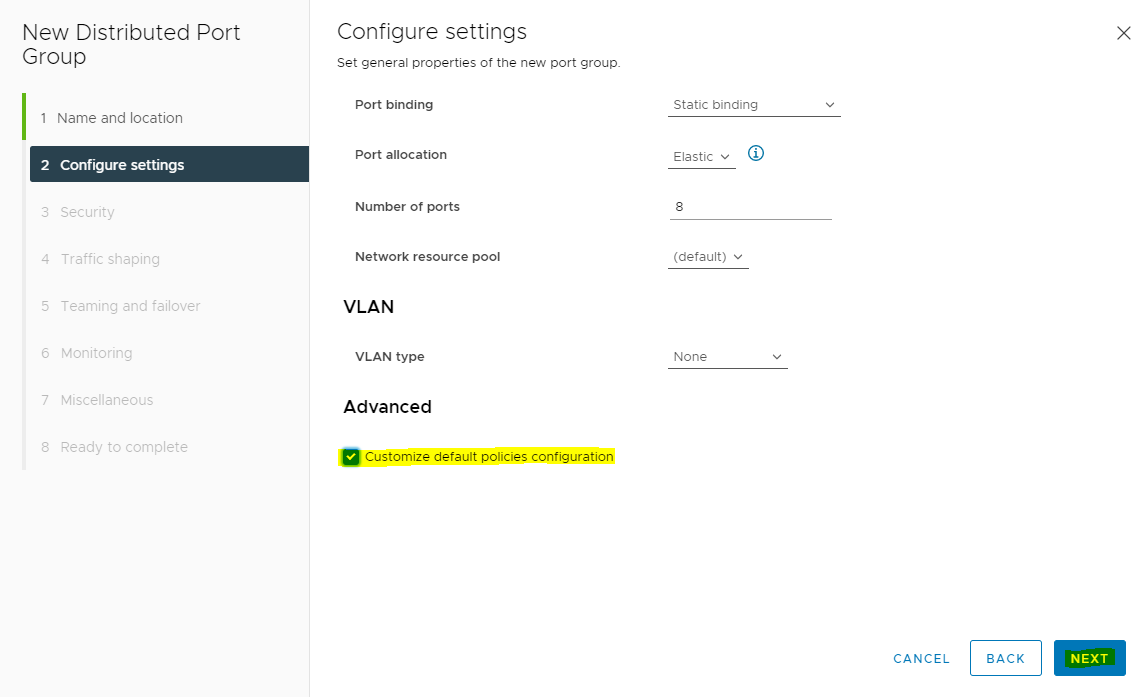
Check Customize default policies configuration checkbox and click Next.
-
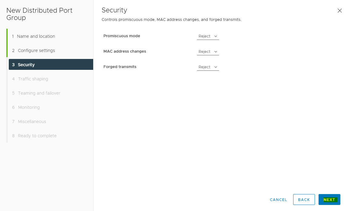
On the Security dialog box, click NEXT.
-
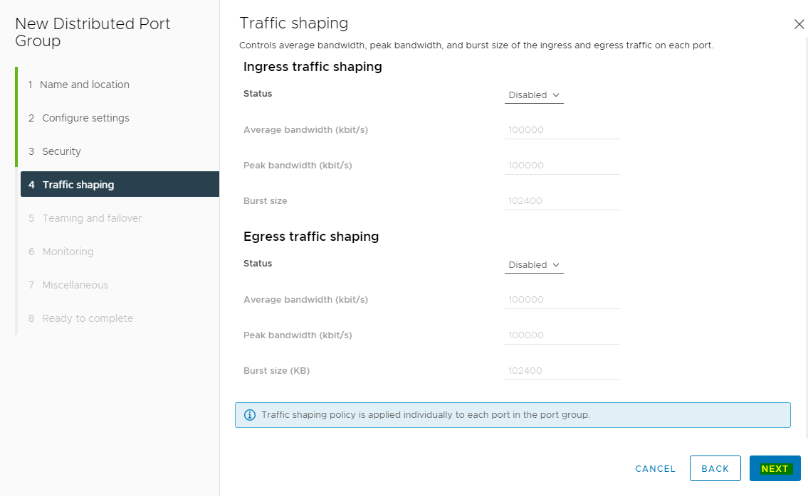
On the Traffic shaping dialog box, click NEXT.
-
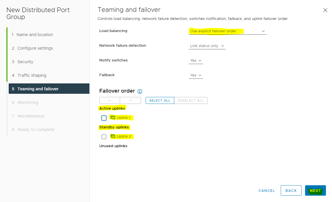
On the Teaming and failover dialog box select Uplink 1 as active uplink and set Uplink 2 to standby uplink. Click NEXT.
-
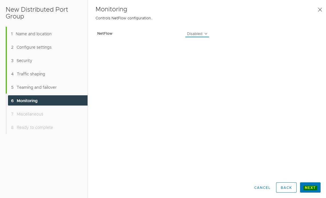
On the Monitoring dialog box set NetFlow to Disabled, and click NEXT.
-
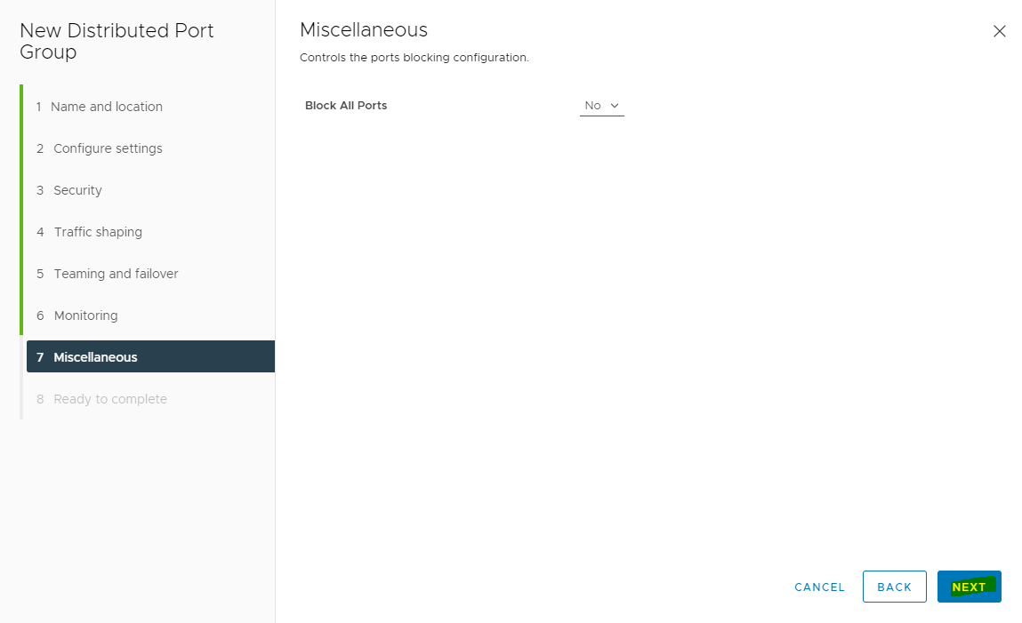
On the Miscellaneous dialog box set Block All Ports to No, and click NEXT.
-
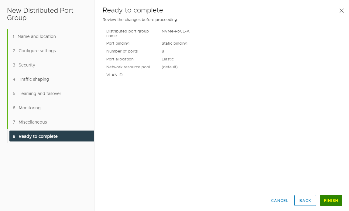
On the Ready to complete dialog box review all the changes before you click Finish.
-
Repeat steps 1 and 9 to create second Distributed Port Group for Storage Traffic with:
The Second Port Group Name <NVMe-RoCE-B>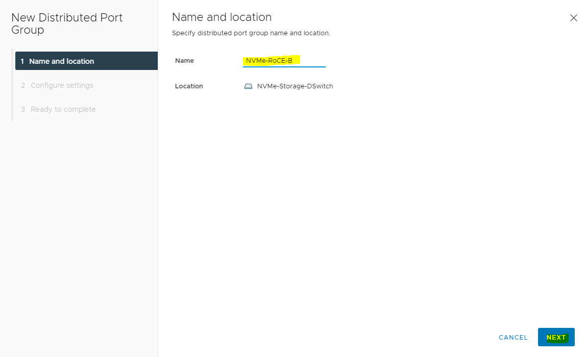
And in the Teaming and failover dialog box select Uplink 2 as active uplink and set Uplink 1 to standby uplink.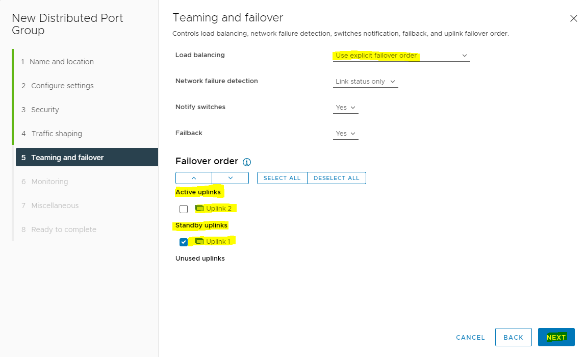
The same steps are applicable for both the port groups.
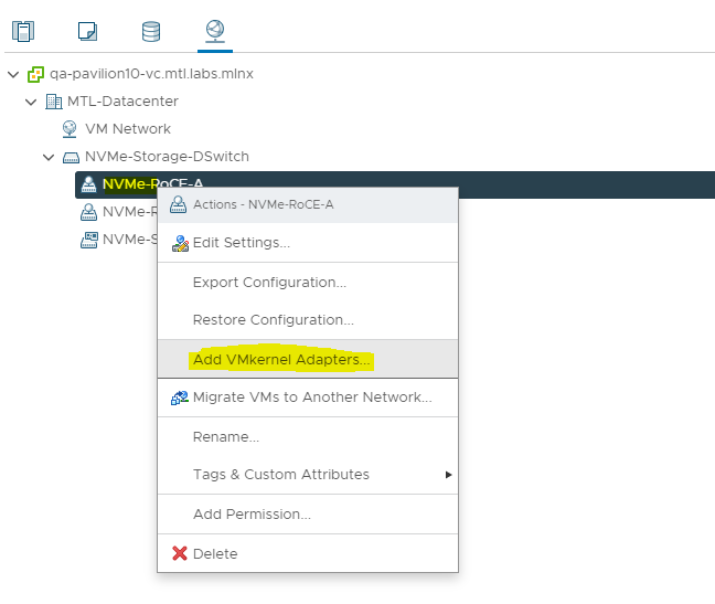
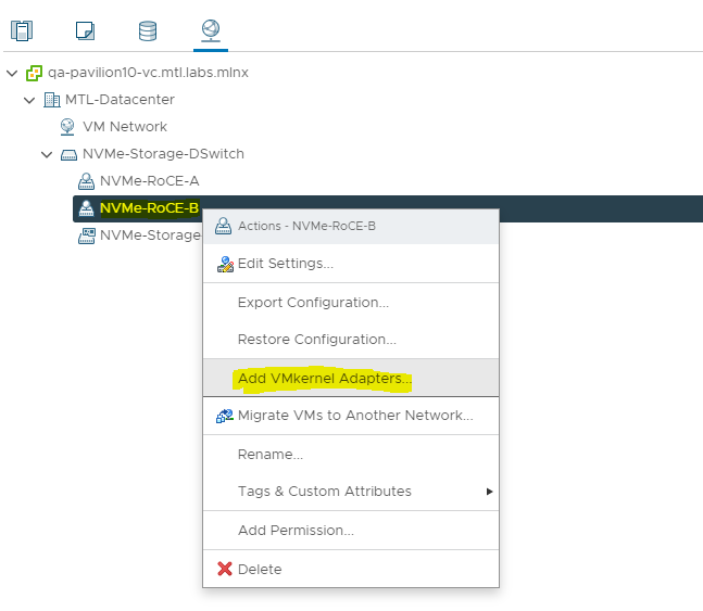
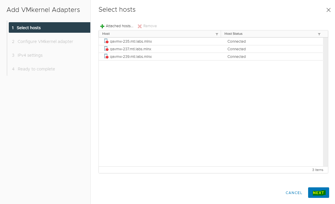
To add VMkernel Adapters for distributed port groups please execute following steps.
-
Right click the distributed port group and select Add VMkernel Adapters.
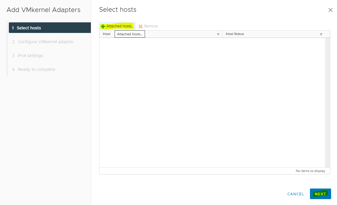
-
Click Add Hosts.
-
Select the hosts and click OK.
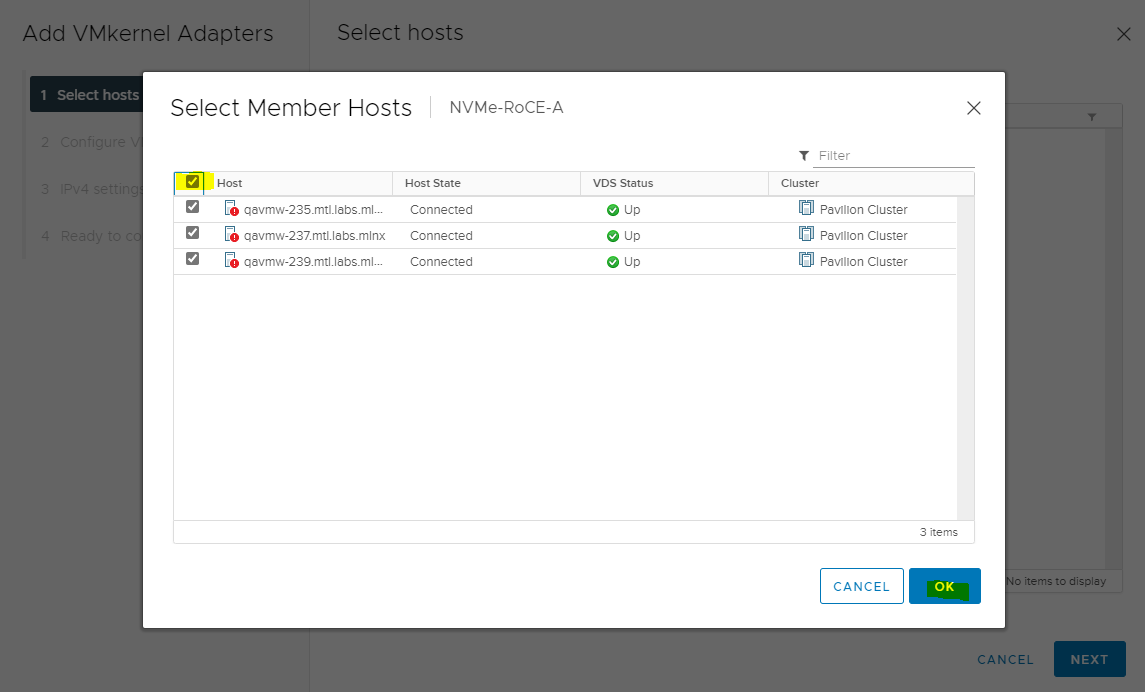
-
Click NEXT on the Select hosts dialog box.
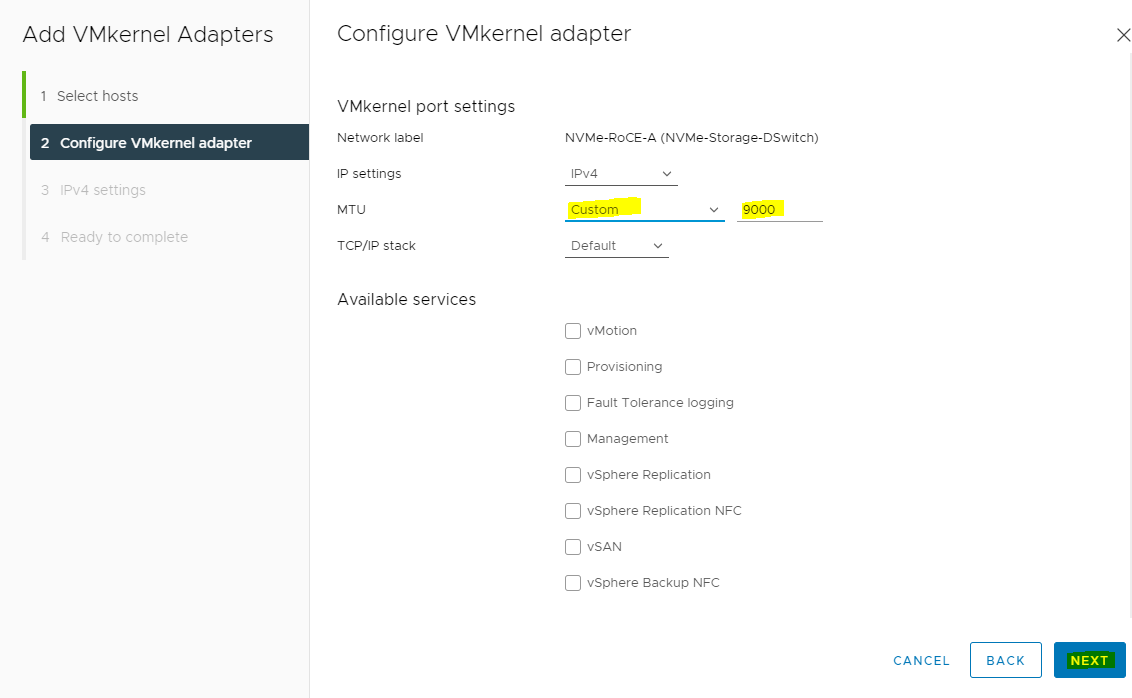
-
Set MTU to 9000 and click NEXT.

-
Enter the Network Settings and Gateway details, and click NEXT.

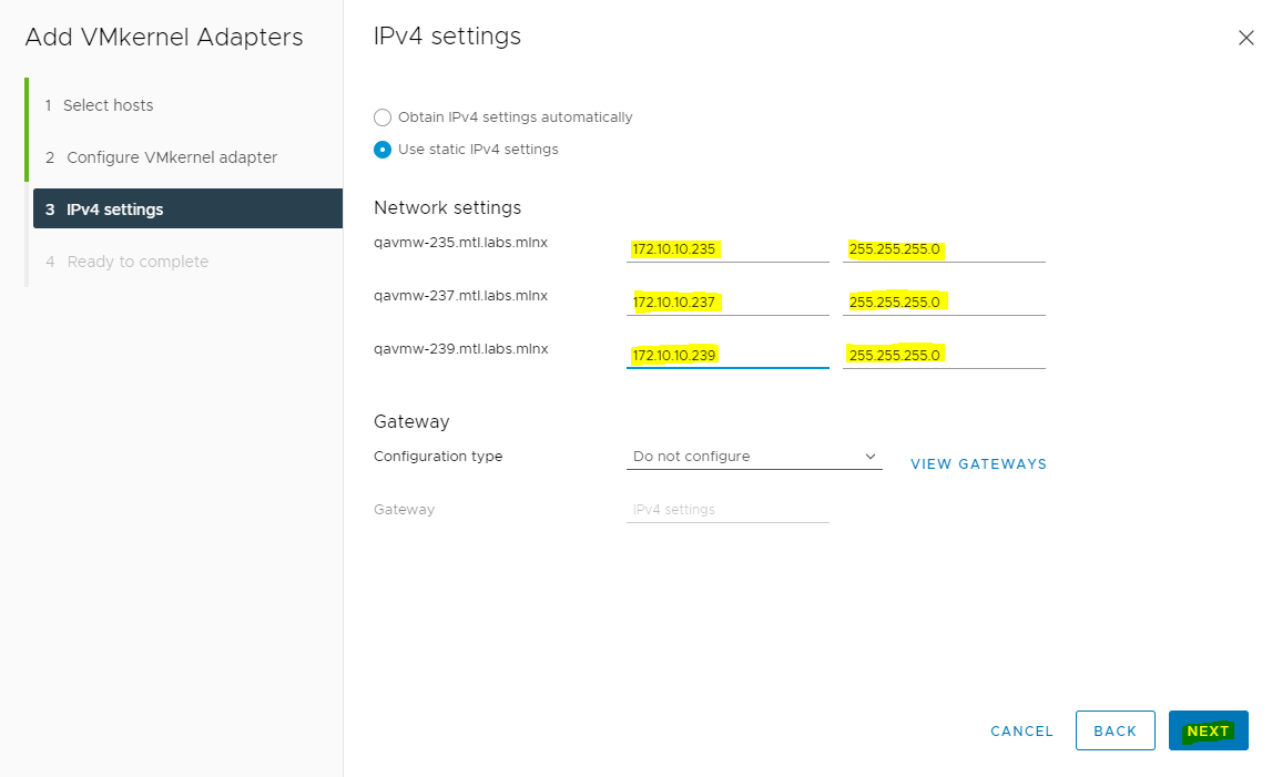
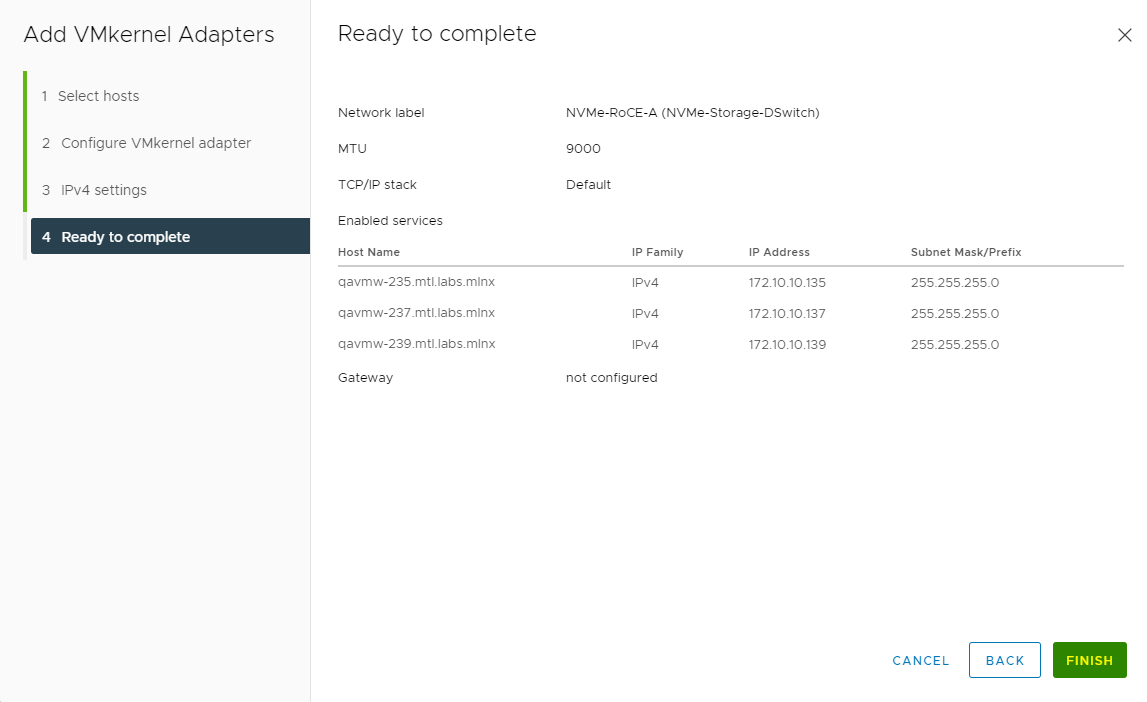
-
Click FINISH.
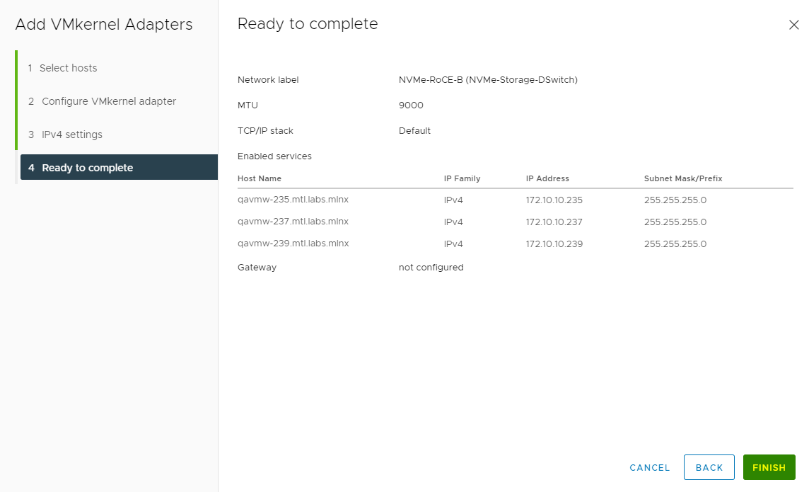
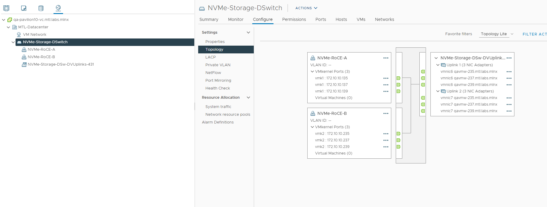
After all the ESXi Cluster Networking configuration is complete, the configuration can be verified under the Distributed Switch>Configure>Topology tab.
VMware Software NVMe over RDMA Storage Adapters configuration
To access Pavilion volumes user needs to create the software NVMe over RDMA Storage Adapters.
-
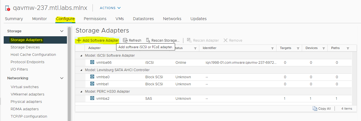
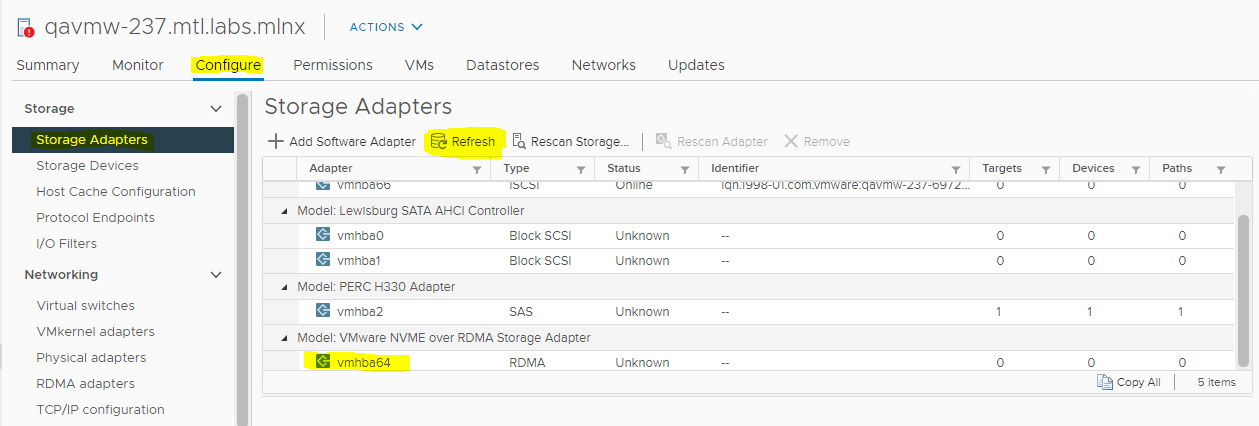
Navigate to Host and Clusters and select the ESXi host, select the Configure tab, locate the Storage section, and select Storage Adapters.
Click Add Software Adapter.
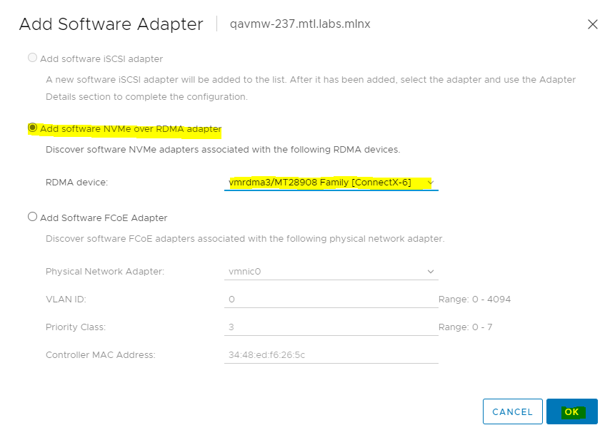
-
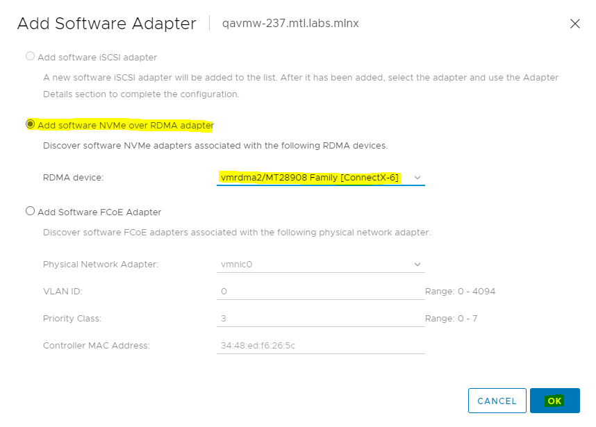
On the Add Software Adapter dialog box, select Add software NVMe over RDMA adapter and select RDMA device as a sample: vmrdma2. Click OK.
-
Verify on the Storage Adapters>Configure tab, that DMA storage adapter vmhba64 has been added.
-
As a next step, select Add Software NVMe over RDMA adapter to add the second RDMA adapter (Sample: vmrdma3).
-
Verify on the Storage Adapters>Configure tab, that DMA storage adapter vmhba65 has been added.
-
Repeat Step 3 through Step 6 to configure VMware NVMe over RDMA Storage Adapter for all the hosts in the cluster.
A NVMe-oF Volume connection
As a next step, required to connect to NVMe-oF volume.
-
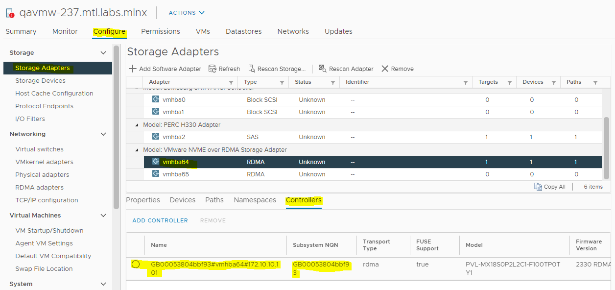
To connect to NVMe-oF volumes, select any hosts in the cluster and select the newly generated vmhba and use the Controllers tab at the bottom of the page to Add Controller.
-
You can Automatically discover controllers or Enter controller details manually. For this instance, the controller is discovered automatically.
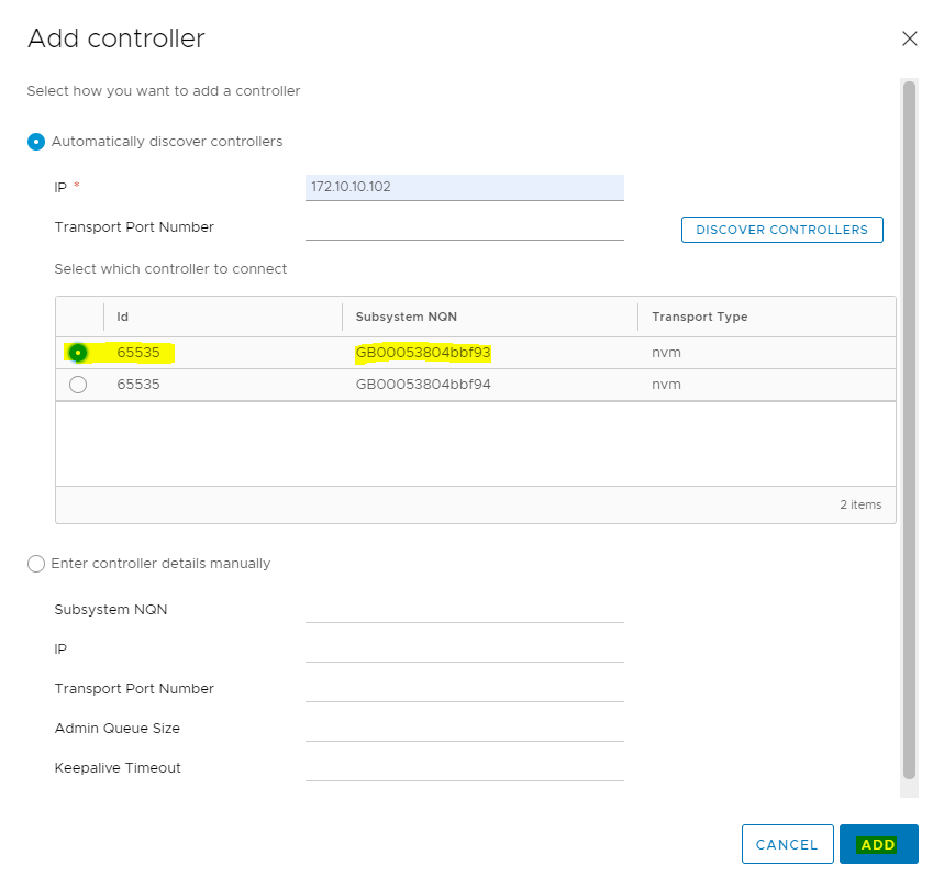
Enter controller IP, Port and click Discover Controllers.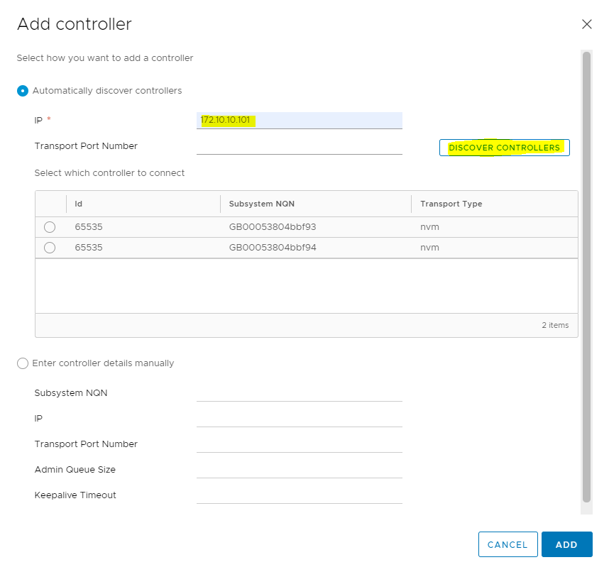
-
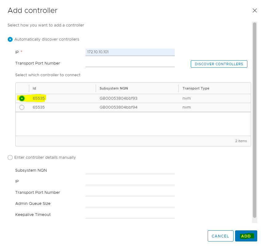
On the Add Controller dialog box select NQN ...f93 and click ADD.
-
Verify that Connectivity through the controller with IP address 172.10.10.101 has been established.
-
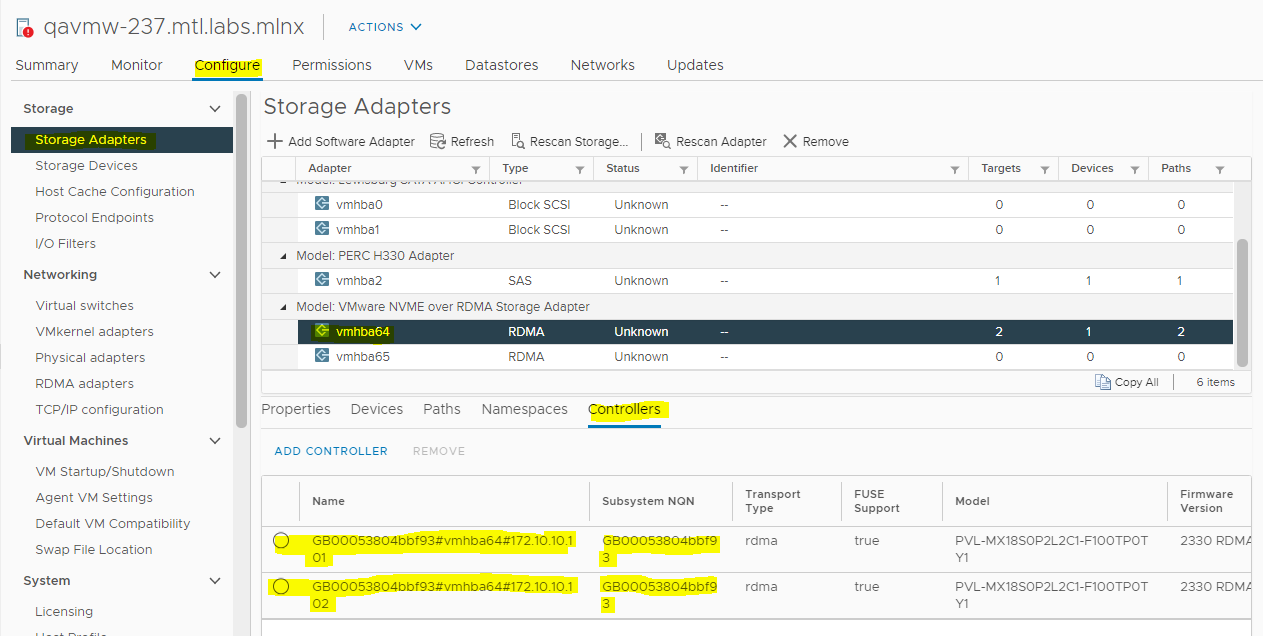
Now Connect through the other controller IP address. Select the NQN and click ADD.
-
Connectivity through Active and Standby controllers is established, as seen in the below image.
-
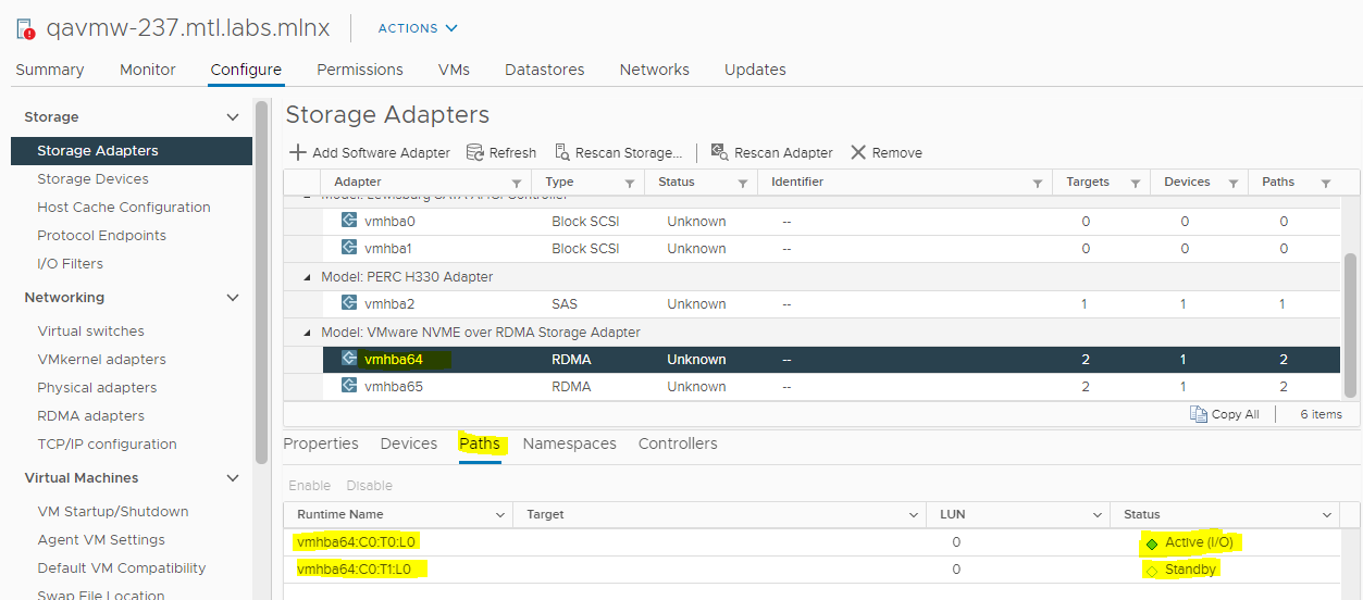
Verify Paths.
-
Verify Host to the NVMe Device.
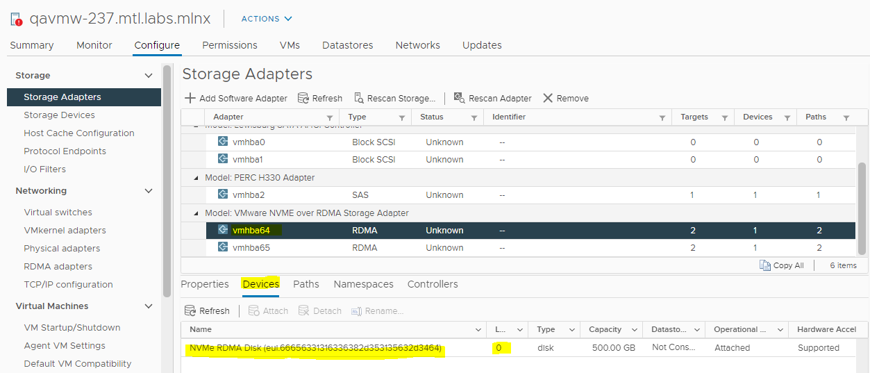
-
In a similar manner you can connect to all the hosts in the ESX cluster and verify that the hosts can see the NVMe device.
Multipathing Configuration
-
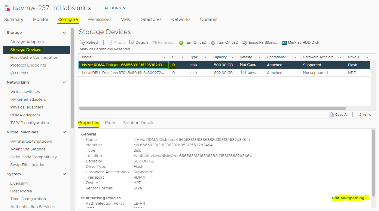
After adding controllers, navigate to Storage>Storage devices and then after selecting the NVME device click Edit Multipathing as can be seen at the bottom-right corner of the page in the image.
-
Select vmhba with Active (I/O)and set Path selection policy to FIXED.
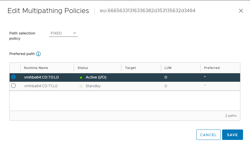
-
In a similar manner, configure multipathing for all the hosts in the ESX cluster.
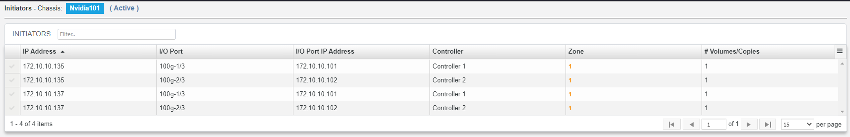
Initiators Verification in Pavilion HFA
To verify Pavilion HFA initiators, login to Pavilion GUI, navigate to Storage>Volumes and verify Initiators tab displayed at the bottom of the page, when you select a volume.
VMFS Filesystem and Datastore creation
To create datastore and VMFS filesystem:
-
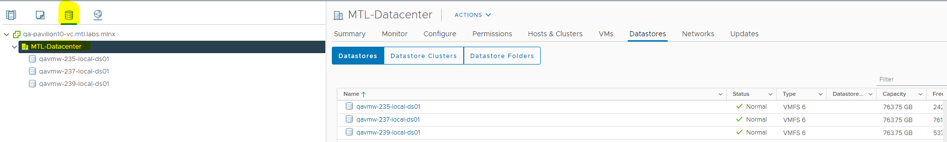
Log in to the VMware® vSphere™ Client.
-
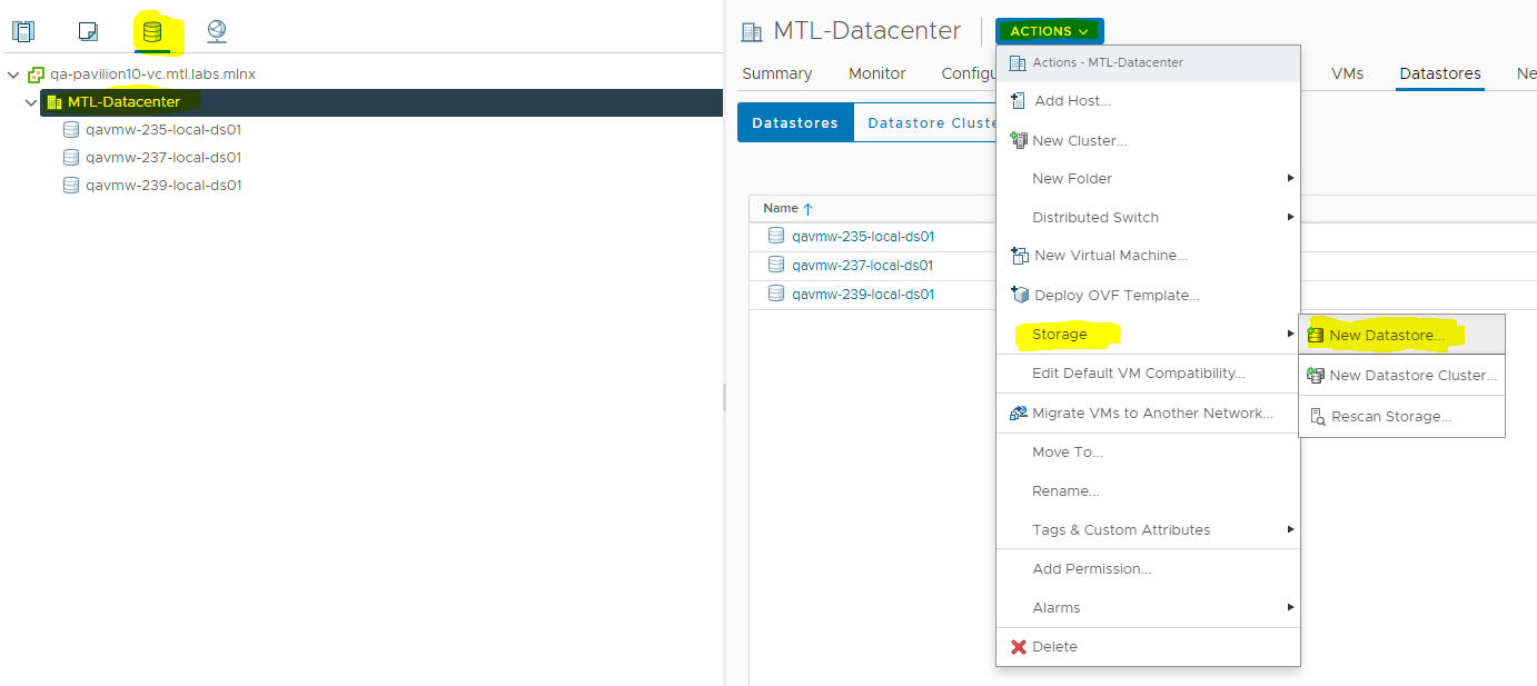
At vCenter, click on the storage icon.
-
Navigate to Actions>Storage>New Datastore.
-
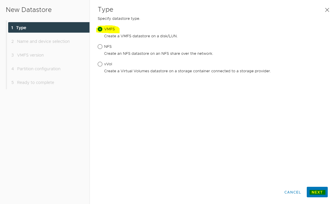
On the New Datastore dialog box, select Type, Select Datastore Type as VMFS and click NEXT.
-
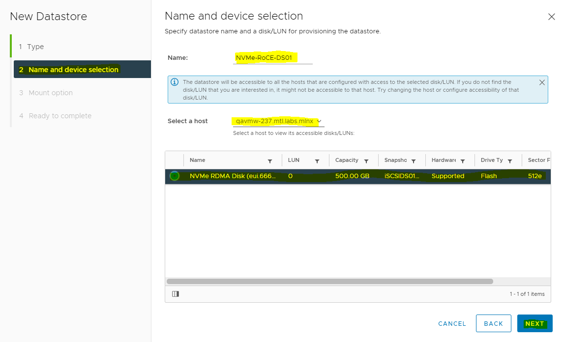
Enter the Datastore name, and click NEXT.
-
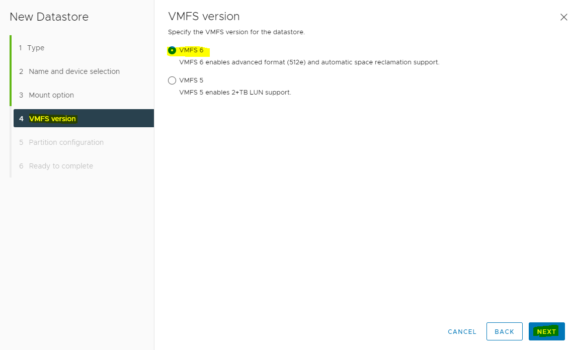
Select VMFS Version and click NEXT.
-
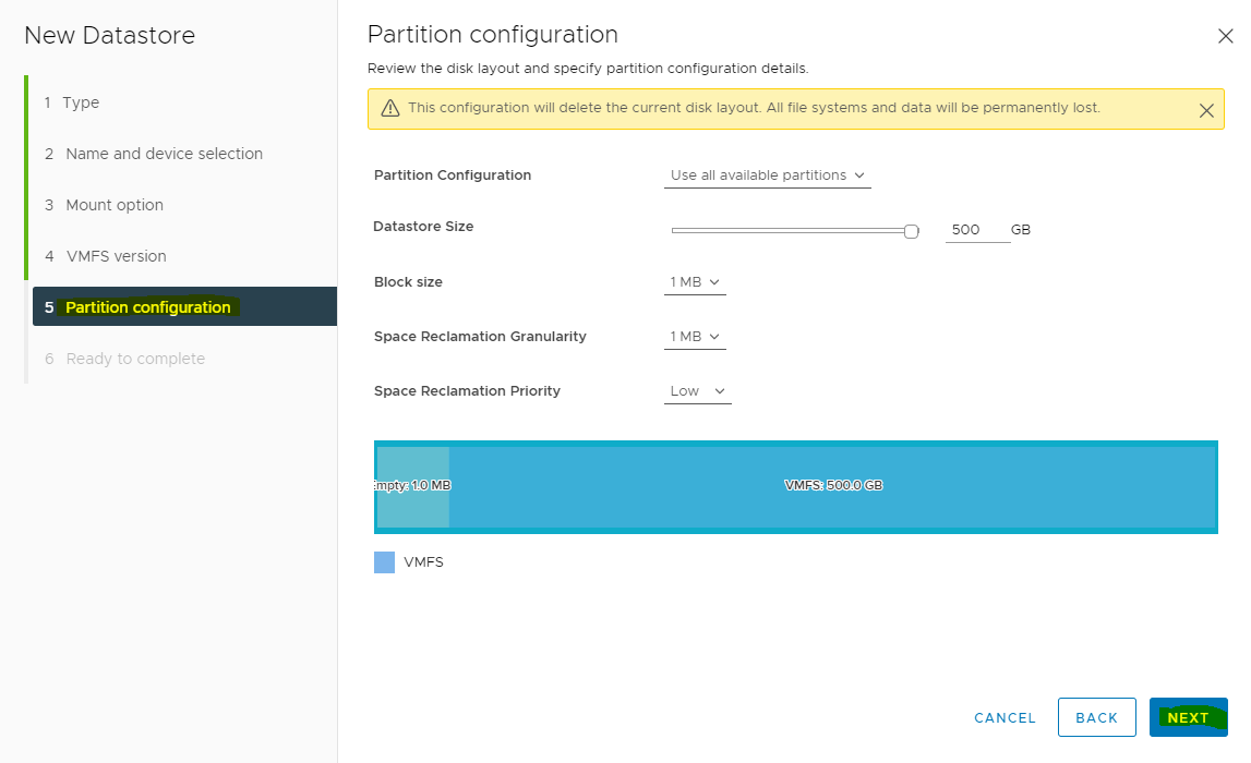
Specify Partition configuration and click NEXT.
-
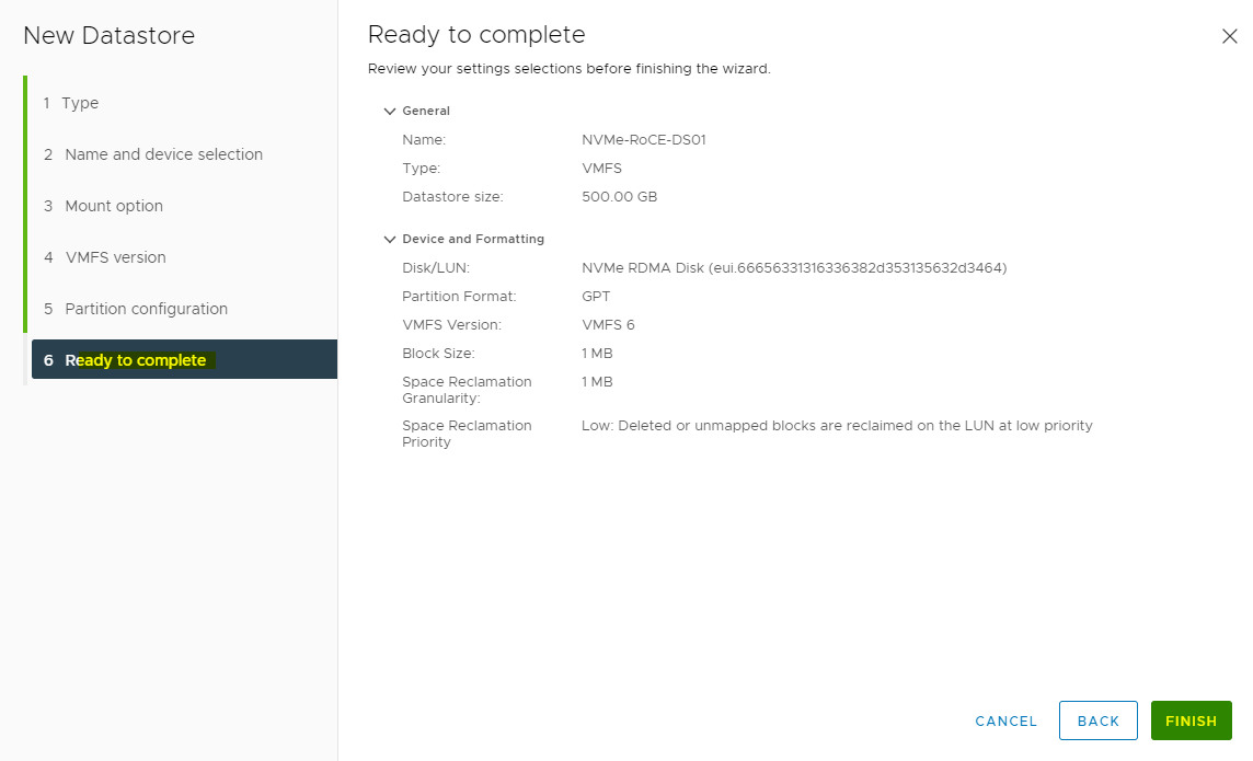
Verify datastore information and click FINISH.
-
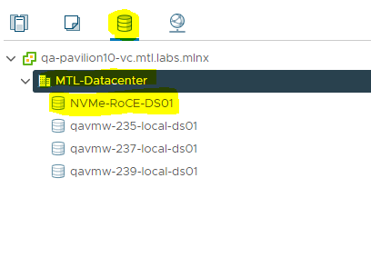
Now, verify that new datastore NVME-Datastore is created and is ready for use.
Add NVMe-oF disk to Virtual Machine
As a thumb rule, for I/O intensive workloads, VMs should have their virtual disks connected using the VMware vNVMe Controller and not the standard VMware SCSI or SATA controllers, as long as the client operating system supports NVMe technology.
Modern Microsoft Windows Server and Linux distributions all natively support NVMe, so for new deployments this is not an issue. However, for older Microsoft Windows Server distributions which do not natively support NVMe, the VMware paravirtualized SCSI or SATA, or even emulates LSI SATA controllers will still function, albeit at reduced performance potential.
To proceed with VM creation, ensure that you select the Pavilion datastore. This section lists the steps to perform the transaction.
-
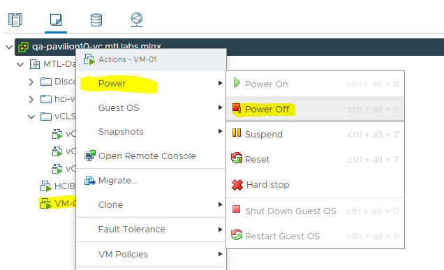
Navigate back to Host and Clusters in VMware® vSphere™, power Off VM and right click on a Virtual Machine.
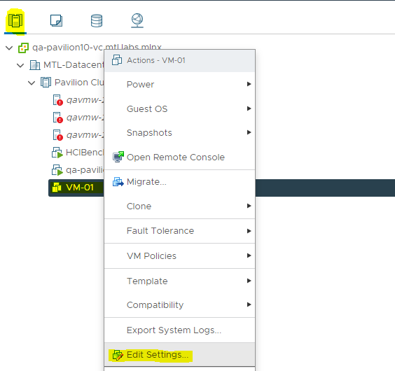
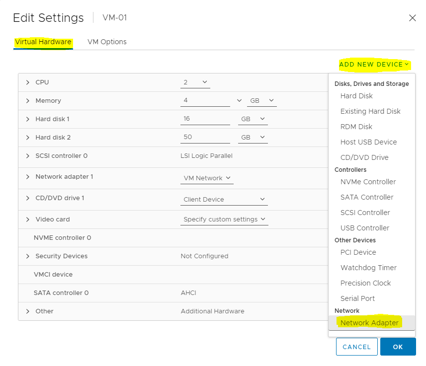
-
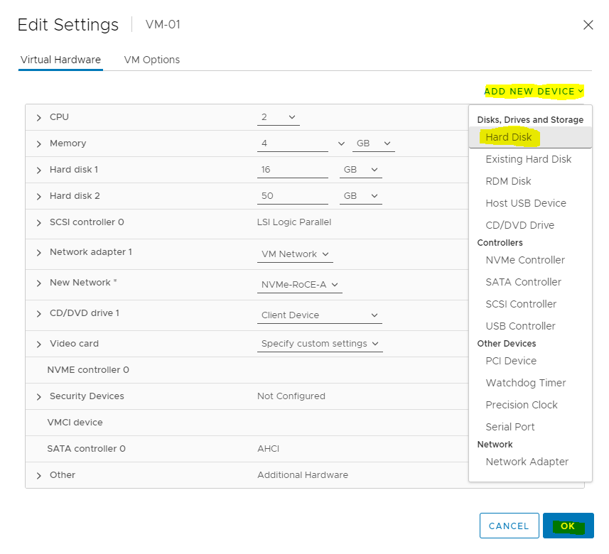
In the Virtual Hardware, click on ADD NEW DEVICE and select Network Adapter.
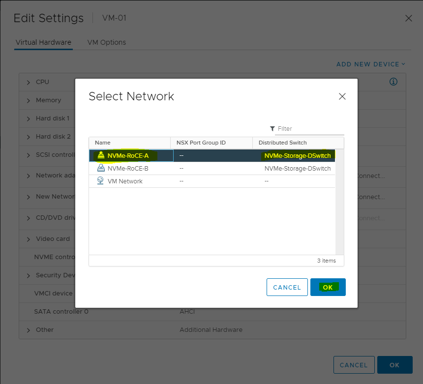
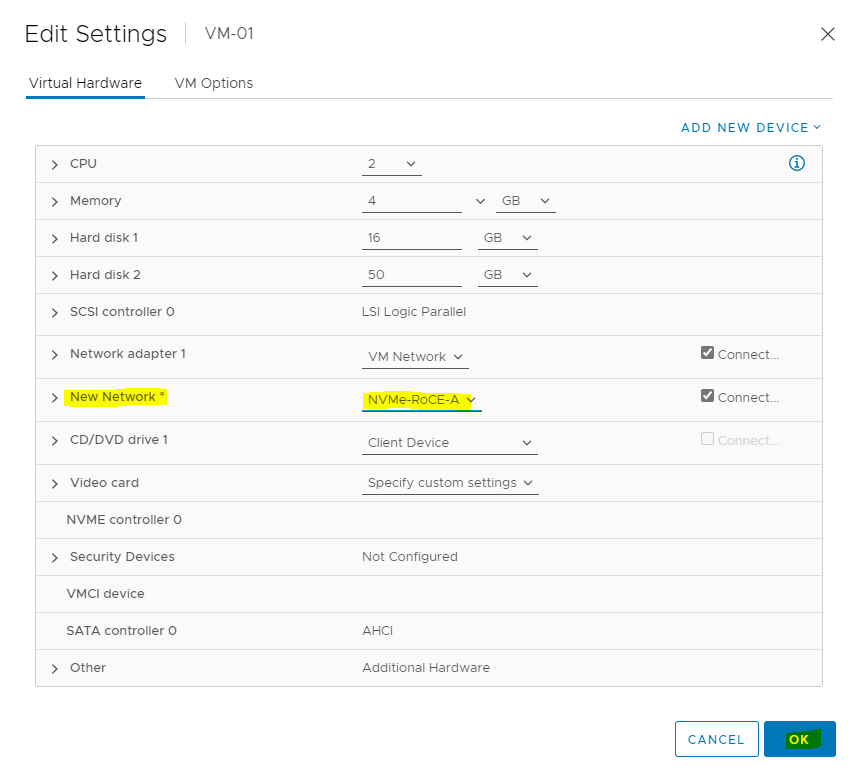
-
Set the New Network to Browse, select Network and click NEXT.
-
Add new Hard Disk and specify the size. Click OK.
-
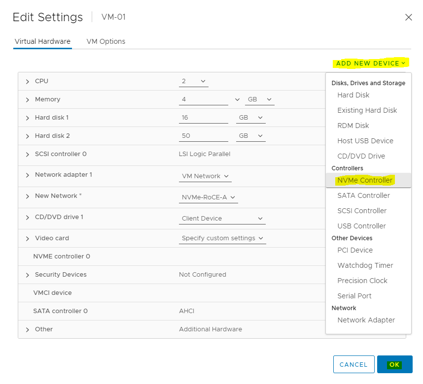
Select the ADD NEW DEVICE button and select NVMe Controller. Click OK.
-
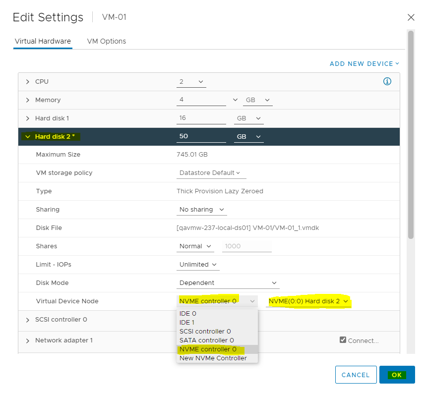
Open the New Hard Disk line item and select the new NVMe controller just added. Click OK.
-
Power On the VM.
-
With the virtual NVMe controller, the hard drives will not appear in Linux under the typical /dev/sd[a-z] or /dev/hd[a-z] device nodes.
Instead, they appear under the new device nodes /dev/nvme0n1.
To verify the same, enter the following command:VM console
nvme list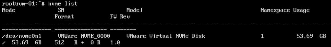
Disconnecting from a NVMe Datastore
The following steps are required to disconnect from a NVMe datastore.
-
Login to vCenter and navigate to VMs and Templates.
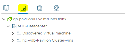
-
Power Off the VM.
-
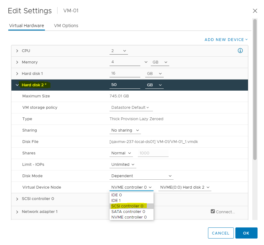
Change Hard disk 2 NVMe controller controller to SCSI controller.
-
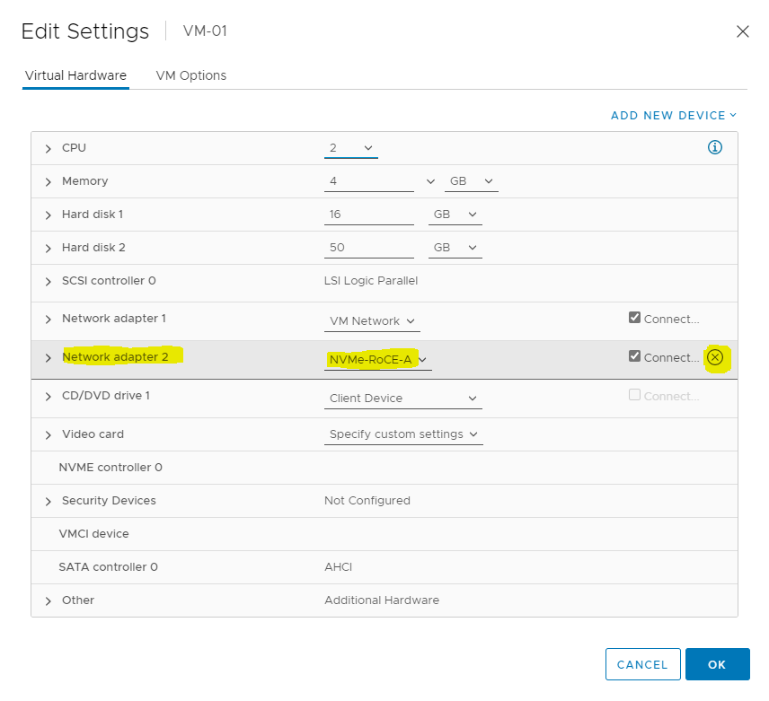
Remove the VM Network adapter 2.
-
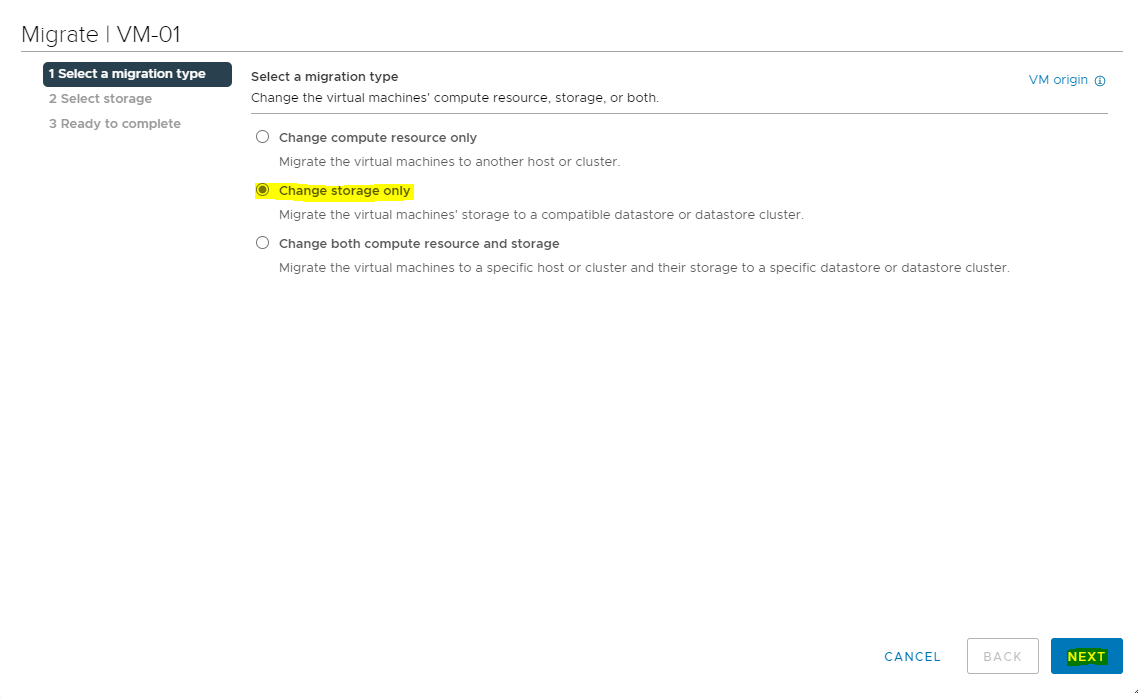
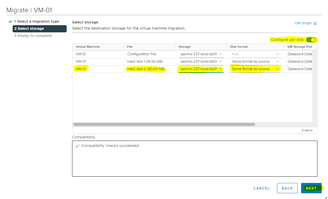
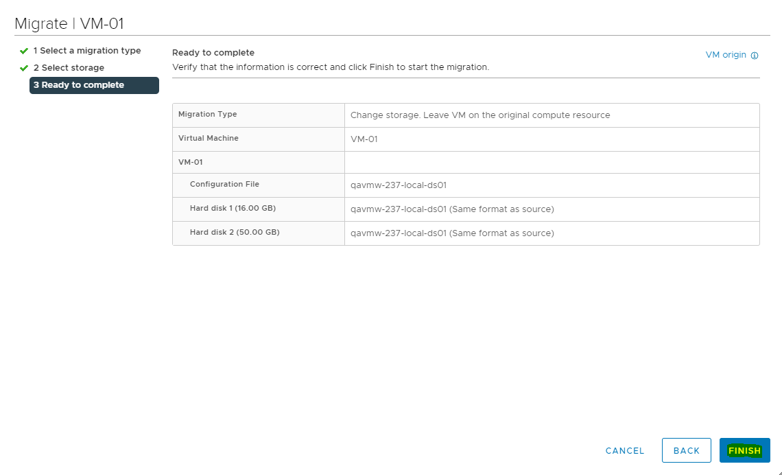
Migrate the VM to another Datastore.
-
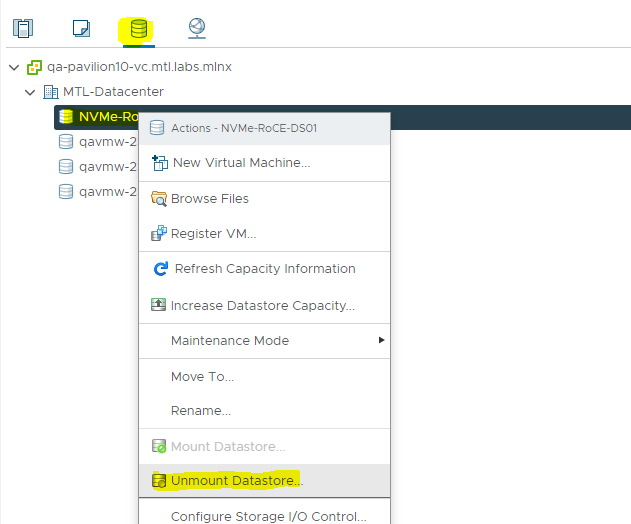
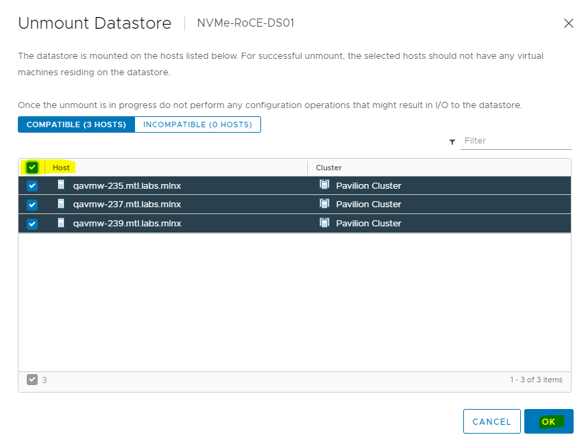
Navigate to Storage. Right click the datastore and select Unmount Datastore,
-
Select all the Hosts in the cluster and click OK.
-
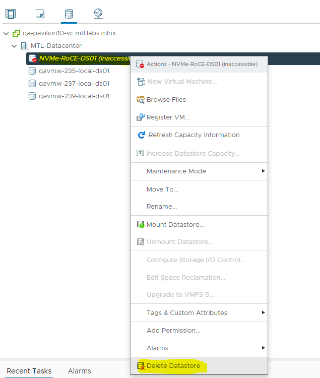
Select the datastore and right click to Delete Datastore.
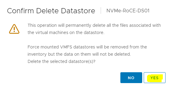
-
Make sure VMs are migrated to another datastore before you click YES.
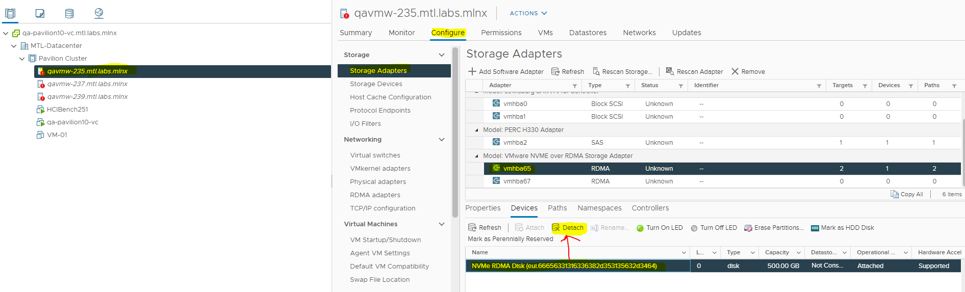
-
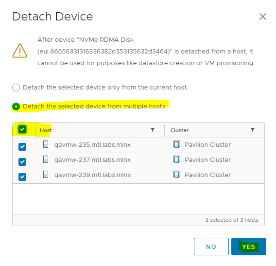
From any host in the cluster navigate to Storage Adapters, select the NVMe device and click Detach.
Be cautious before you proceed with the step.
-
On the Detach Device dialog box, select all the hosts in the ESXi Cluster.
-
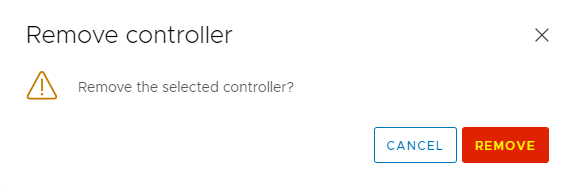
For each vmhba select the controllers and click Remove.
Be cautious before you proceed with the step.
Click REMOVE.
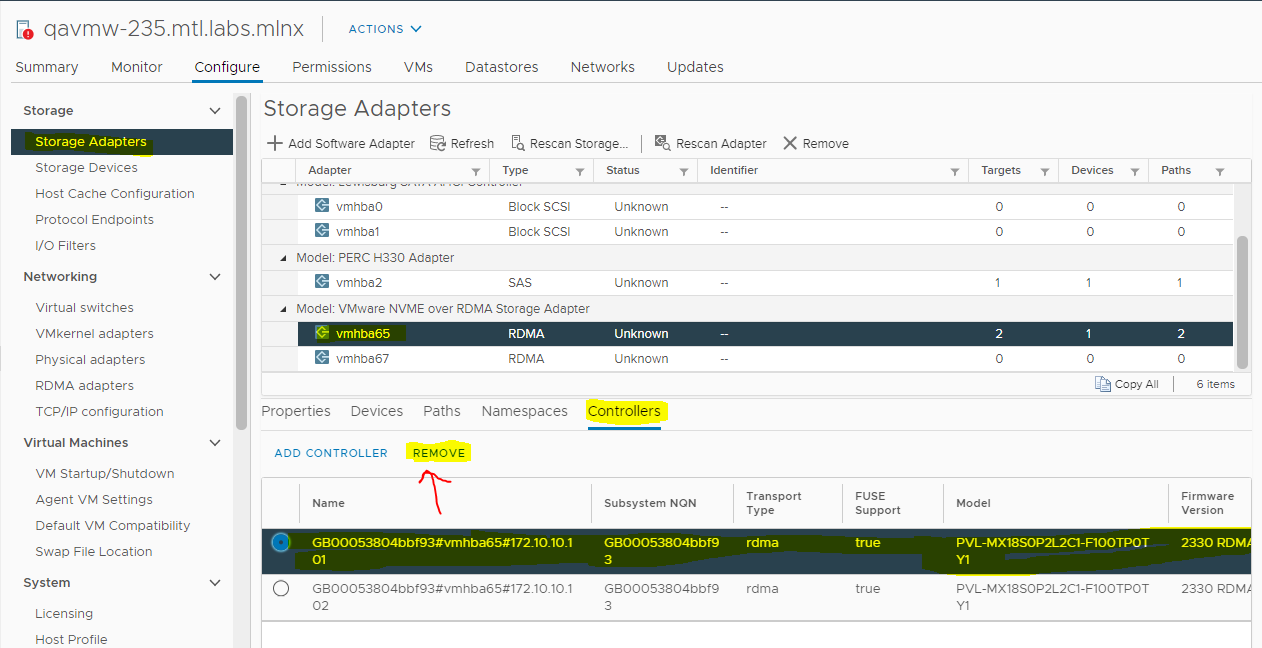
-
Perform above steps to Remove controllers for the second adapter vmhba65.
-
In a similar manner, Remove Controllers from all hosts in the ESX cluster.
Done!
Appendix
Test Environment
Hardware and Software Components
Host under test:
• Dell PowerEdge™ R740 host, with 2 x Intel® Xeon® Gold 5218R CPUs (20 cores @ 2.10 GHz each), 96GB of RAM.
• Dual-port NVIDIA ConnectX®-6 Dx Adapter Card, with the default driver version.
• VMware ESXi™ 7.0 Update 1
Pavilion HFA:
• Pavilion HFA v2.3.3.0_11378
Network:
• NVIDIA Spectrum® SN3700 Open Ethernet Switch
Cumulus Linux 4.2 Network OS
• NVIDIA MCP1650-H001E30 Passive Copper Cable InfiniBand HDR up to 200Gb/s QSFP56 LSZH 1m Black Pulltab 30AWG
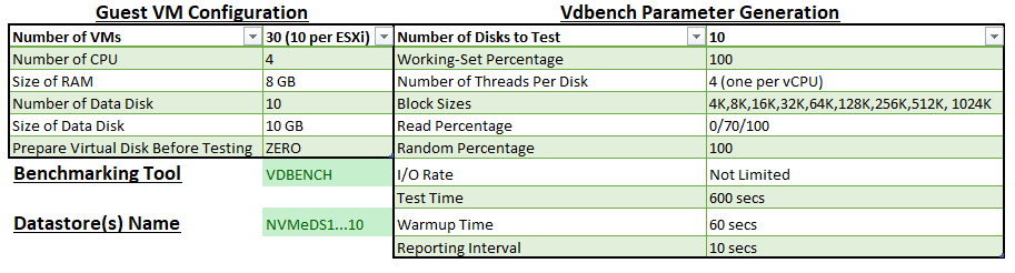
Virtual Machine and Benchmark Configuration
We used HCI Bench v2.5.1 VDBENCH benchmark workloads to measure performance with following Virtual Machines (Ubuntu 18.04) and VDBENCH parameter configurations:
Performance Results
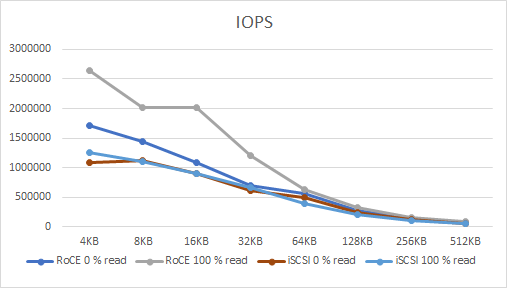
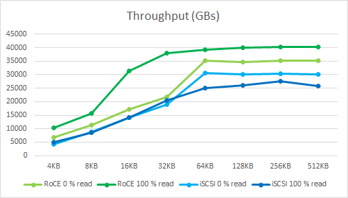
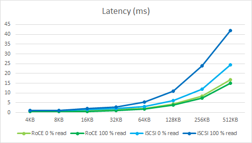
The HCI Bench used Random Read and Random Write IO patterns with various IO sizes from 4 KB to 512 KB.
We compare the IOPS, Throughput and Latency between NVMe over RoCE and iSCSI targets on a Pavilion HFA.
The benchmark runs had the virtual disks placed on two Media Groups with 10 controllers.
Please note that these results were obtained using a VDBECH benchmark and with our lab configurations.
Performance with other configurations, number of ESXi servers may vary.
Conclusion
The benchmark results in this performance study show consistent supremacy of NVMe over RoCE protocol for all block sizes tested and shows that NVMe over RoCE was able to achieve twice the IOPS and 50% more Throughput with lower latencies compared to iSCSI for every IO size tested.
NVMe over RoCE can also allowing to be run more VMs on the same hardware.
Authors
|
|
Boris Kovalev
Boris Kovalev has worked for the past several years as a Solutions Architect, focusing on NVIDIA Networking/Mellanox technology, and is responsible for complex machine learning, Big Data and advanced VMware-based cloud research and design. Boris previously spent more than 20 years as a senior consultant and solutions architect at multiple companies, most recently at VMware. He has written multiple reference designs covering VMware, machine learning, Kubernetes, and container solutions which are available at the NVIDIA Documents website. |

Last updated: