Created on January 6, 2026
Scope
This Reference Deployment Guide (RDG) provides detailed instructions for deploying a Kubernetes (K8s) cluster using the DOCA Platform Framework (DPF) in Host-Trusted mode, and utilizing the SNAP DPU Service with Virtio-FS. The guide focuses on setting up an accelerated Host-Based Networking (HBN) service on NVIDIA® BlueField®-3 DPUs to deliver secure, isolated, and hardware-accelerated environments, and utilizing the SNAP VirtIO-FS DPU service which provides a VirtIO-FS CSI to the cluster via the DPU using an external storage target (NFS).
This guide is designed for experienced system administrators, system engineers, and solution architects who seek to deploy high-performance Kubernetes clusters with Host-Based Networking enabled on NVIDIA BlueField DPUs and a VirtIO-FS CSI provided from an external storage target.
-
This reference implementation, as the name implies, is a specific, opiniated deployment example designed to address the use case described above.
-
While other approaches may exist to implement similar solutions, this document provides a detailed guide for this particular method.
Abbreviations and Acronyms
|
Term |
Definition |
Term |
Definition |
|---|---|---|---|
|
BFB |
BlueField Bootstream (OS Image) |
RDG |
Reference Deployment Guide |
|
BGP |
Border Gateway Protocol |
RDMA |
Remote Direct Memory Access |
|
CNI |
Container Network Interface |
SFC |
Service Function Chaining |
|
CSI |
Container Storage Interface |
SNAP |
Storage-Defined Network Accelerated Processing |
|
DOCA |
Data Center Infrastructure-on-a-Chip Architecture |
SR-IOV |
Single Root Input/Output Virtualization |
|
DPF |
DOCA Platform Framework |
TOR |
Top of Rack |
|
DPU |
Data Processing Unit |
VLAN |
Virtual LAN (Local Area Network) |
|
GENEVE |
Generic Network Virtualization Encapsulation |
VNI |
Virtual Network Interface |
|
HBN |
Host Based Networking |
VRF |
Virtual Router/Forwarder |
|
IPAM |
IP Address Management |
VRR |
Virtual Router Redundancy |
|
K8S |
Kubernetes |
VTEP |
Virtual Tunnel End Point |
|
MAAS |
Metal as a Service |
|
|
Introduction
The NVIDIA BlueField-3 Data Processing Unit (DPU) is a 400 Gb/s infrastructure compute platform designed for line-rate processing of software-defined networking, storage, and cybersecurity workloads. It combines powerful compute resources, high-speed networking, and advanced programmability to deliver hardware-accelerated, software-defined solutions for modern data centers.
NVIDIA DOCA unleashes the full potential of the BlueField platform by enabling rapid development of applications and services that offload, accelerate, and isolate data center workloads.
One such service is Host-Based Networking (HBN) - a DOCA-enabled solution that allows network architects to design networks based on Layer 3 (L3) protocols. HBN enables routing on the server side by using BlueField as a BGP router. It encapsulates key networking functions in a containerized service pod, deployed directly on the BlueField’s ARM cores.
Another such service is SNAP, which has both Block Device and File System modes. In this RDG, we will demonstrate its file system mode - Virtio-FS, that provides file system storage provided to the cluster from an external storage target (NFS).
In this solution, the SNAP Virtio-fs service deployed via NVIDIA DOCA Platform Framework (DPF) is composed of multiple functional components packaged into containers, which DPF orchestrates to run together with HBN. DPF simplifies DPU management by providing orchestration through a Kubernetes API. It handles the provisioning and lifecycle management of DPUs, orchestrates specialized DPU services, and automates tasks such as service function chaining (SFC).
This RDG extends the capabilities of the DPF-managed Kubernetes cluster described in the RDG for DPF Host-Trusted with HBN DPU Service (referred to as the "Baseline RDG") by adding the SNAP DPU Service in Virtio-fs mode. It demonstrates performance optimizations, including Jumbo frame implementation, with results validated through an iperf3 TCP test and a standard FIO workload test.
References
Solution Architecture
Key Components and Technologies
-
NVIDIA BlueField® Data Processing Unit (DPU)
The NVIDIA® BlueField® data processing unit (DPU) ignites unprecedented innovation for modern data centers and supercomputing clusters. With its robust compute power and integrated software-defined hardware accelerators for networking, storage, and security, BlueField creates a secure and accelerated infrastructure for any workload in any environment, ushering in a new era of accelerated computing and AI.
-
NVIDIA DOCA Software Framework
NVIDIA DOCA™ unlocks the potential of the NVIDIA® BlueField® networking platform. By harnessing the power of BlueField DPUs and SuperNICs, DOCA enables the rapid creation of applications and services that offload, accelerate, and isolate data center workloads. It lets developers create software-defined, cloud-native, DPU- and SuperNIC-accelerated services with zero-trust protection, addressing the performance and security demands of modern data centers.
-
NVIDIA ConnectX SmartNICs
10/25/40/50/100/200 and 400G Ethernet Network Adapters
The industry-leading NVIDIA® ConnectX® family of smart network interface cards (SmartNICs) offer advanced hardware offloads and accelerations.
NVIDIA Ethernet adapters enable the highest ROI and lowest Total Cost of Ownership for hyperscale, public and private clouds, storage, machine learning, AI, big data, and telco platforms.
-
NVIDIA LinkX Cables
The NVIDIA® LinkX® product family of cables and transceivers provides the industry’s most complete line of 10, 25, 40, 50, 100, 200, and 400GbE in Ethernet and 100, 200 and 400Gb/s InfiniBand products for Cloud, HPC, hyperscale, Enterprise, telco, storage and artificial intelligence, data center applications.
-
NVIDIA Spectrum Ethernet Switches
Flexible form-factors with 16 to 128 physical ports, supporting 1GbE through 400GbE speeds.
Based on a ground-breaking silicon technology optimized for performance and scalability, NVIDIA Spectrum switches are ideal for building high-performance, cost-effective, and efficient Cloud Data Center Networks, Ethernet Storage Fabric, and Deep Learning Interconnects.
NVIDIA combines the benefits of NVIDIA Spectrum™ switches, based on an industry-leading application-specific integrated circuit (ASIC) technology, with a wide variety of modern network operating system choices, including NVIDIA Cumulus® Linux, SONiC and NVIDIA Onyx®.
-
NVIDIA Cumulus Linux
NVIDIA® Cumulus® Linux is the industry's most innovative open network operating system that allows you to automate, customize, and scale your data center network like no other.
-
NVIDIA Network Operator
The NVIDIA Network Operator simplifies the provisioning and management of NVIDIA networking resources in a Kubernetes cluster. The operator automatically installs the required host networking software - bringing together all the needed components to provide high-speed network connectivity. These components include the NVIDIA networking driver, Kubernetes device plugin, CNI plugins, IP address management (IPAM) plugin and others. The NVIDIA Network Operator works in conjunction with the NVIDIA GPU Operator to deliver high-throughput, low-latency networking for scale-out, GPU computing clusters.
-
Kubernetes
Kubernetes is an open-source container orchestration platform for deployment automation, scaling, and management of containerized applications.
-
Kubespray
Kubespray is a composition ofAnsible
playbooks, inventory, provisioning tools, and domain knowledge for generic OS/Kubernetes clusters configuration management tasks and provides:
-
A highly available cluster
-
Composable attributes
-
Support for most popular Linux distributions
-
-
RDMA
RDMA is a technology that allows computers in a network to exchange data without involving the processor, cache or operating system of either computer.
Like locally based DMA, RDMA improves throughput and performance and frees up compute resources.
Solution Design
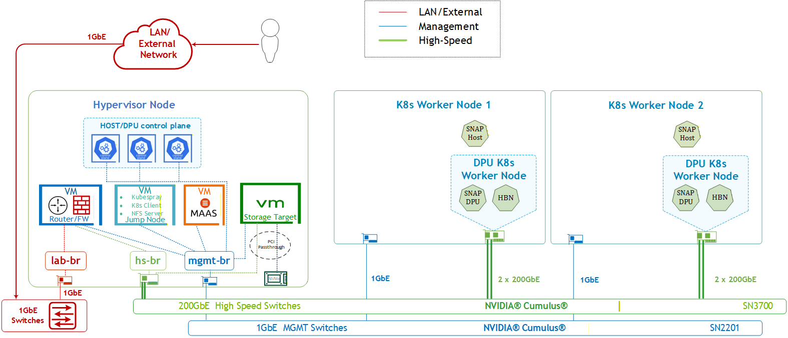
Solution Logical Design
The logical design includes the following components:
-
1 x Hypervisor node (KVM-based) with ConnectX-7
-
1 x Firewall VM
-
1 x Jump VM
-
1 X MaaS VM
-
3 x K8s Master VMs running all K8s management components
-
1 x Storage Target VM
-
-
2 x Worker nodes (PCI Gen5), each with 1 x BlueField-3 NIC
-
Single High-Speed (HS) switch
-
1 Gb Host Management network
HBN service Logical Design
The HBN+SNAP-VirtioFS services deployment leverages the Service Function Chaining (SFC) capabilities inherent in the DPF system, as described in the Baseline RDG for the HBN DPU Service (refer to section "Infrastructure Latency & Bandwidth Validation"). The following SFC logical diagram displays the complete flow for all of the services involved in the implemented solution:
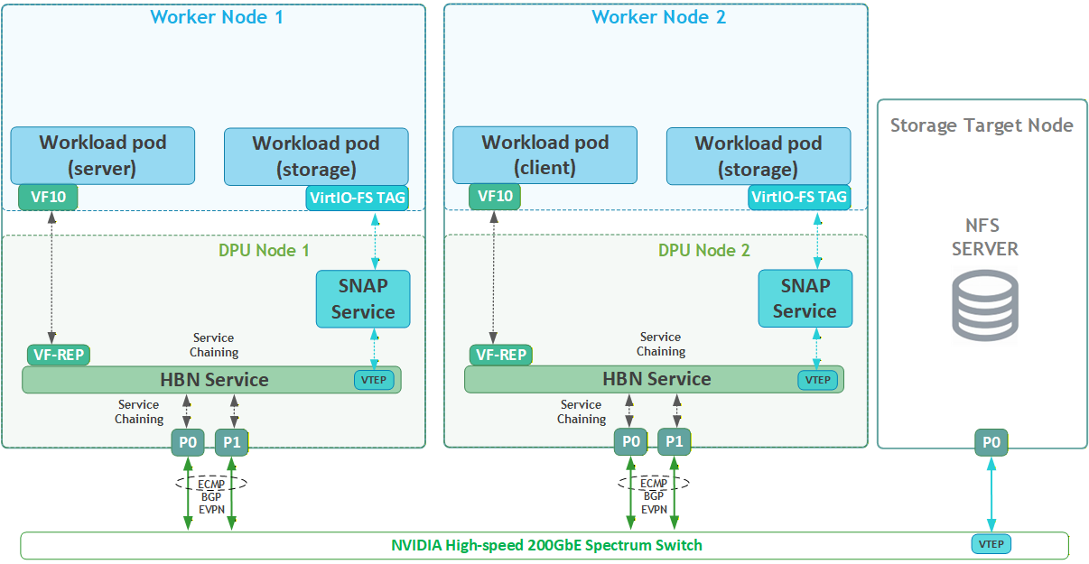
Volume Emulation Logical Diagram
The following logical diagram demonstrates the main components involved in a volume mount procedure to a workload pod.
In the Host Trusted mode, the hosts runs the SNAP CSI plugin, which performs all necessary actions to make storage resources available to the host. Users can utilize Kubernetes Storage APIs (StorageClass, PVC, PV, VolumeAttachment) to provision and attach storage to the host. Upon creation of PersistentVolumeClaim (PVC) object in the host cluster that references a storage class that specifies the SNAP CSI Plugin as its provisioner, the DPF storage subsystem components bring a NFS volume via NFS-kernel client to the required DPU K8s worker node. The DOCA SNAP service then emulates it as a Virtio-fs volume and presents the networked storage as local file system device to the host, which when requested by the kubelet is mounted into the Pod namespace by the SNAP CSI Plugin.
For a complete information about the different components involved in the emulation process and how they work together, refer to: DPF Storage Development Guide - NVIDIA Docs.

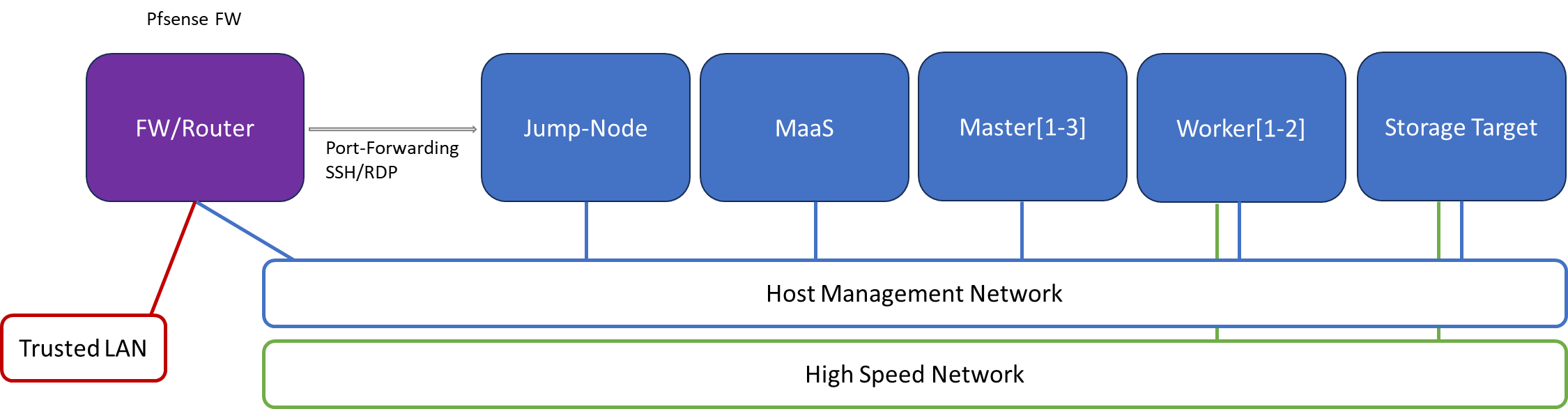
Firewall Design
The pfSense firewall in this solution serves two key roles:
-
Firewall – provides an isolated environment for the DPF system, ensuring secure operations
-
Router – enables Internet access for the management network
Port-forwarding rules for SSH and RDP are configured on the firewall to route traffic to the jump node’s IP address on the host management network. From the jump node, administrators can manage and access various devices in the setup, as well as handle the deployment of both the Kubernetes (K8s) cluster and DPF components.
The following diagram illustrates the firewall design used in this solution:
Software Stack Components
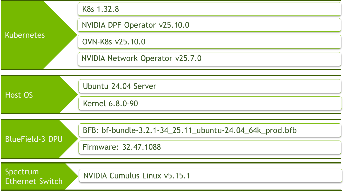
Make sure to use the exact same versions for the software stack as described above.
Bill of Materials
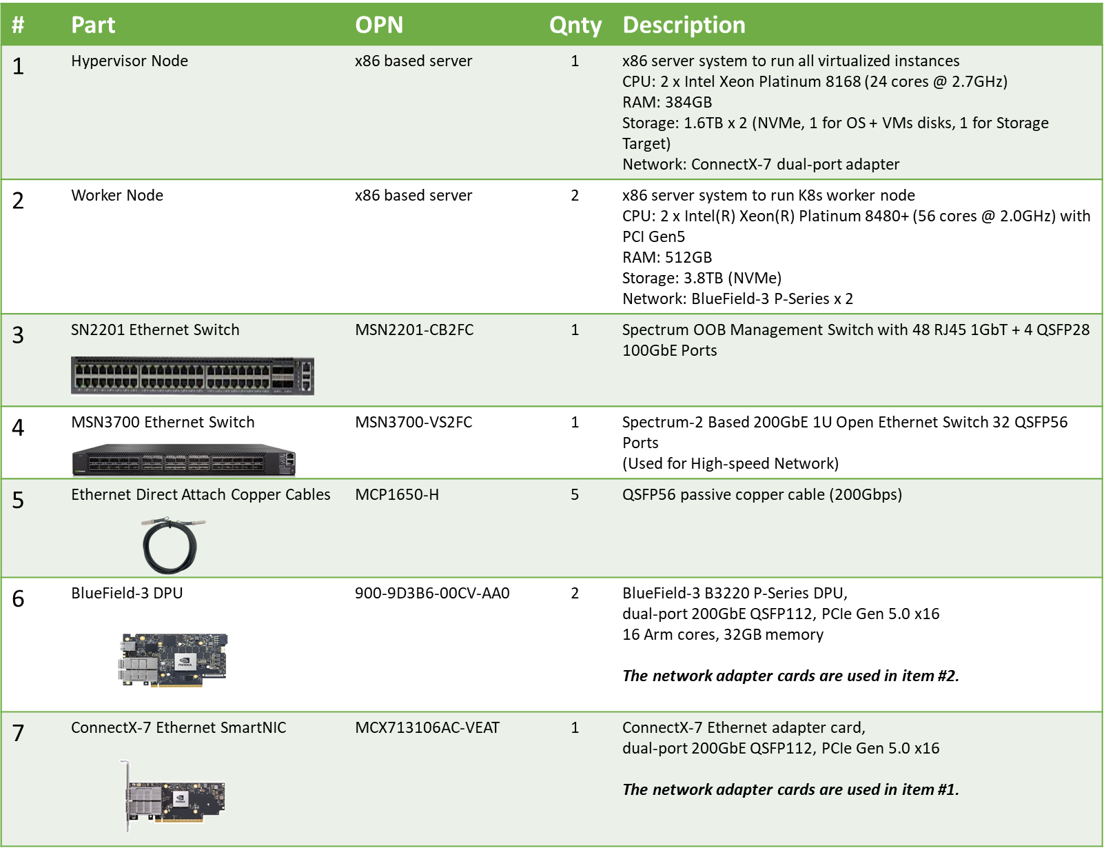
Deployment and Configuration
Node and Switch Definitions
The following definitions and parameters are used to deploy the demonstrated fabric:
|
Switches Ports Usage |
||
|---|---|---|
|
Hostname |
Rack ID |
Ports |
|
|
1 |
swp1-5 |
|
|
1 |
swp1-3 |
|
Hosts |
|||||
|---|---|---|---|---|---|
|
Rack |
Server Type |
Server Name |
Switch Port |
IP and NICs |
Default Gateway |
|
Rack1
|
Hypervisor Node |
|
mgmt-switch: hs-switch: |
mgmt-br (interface eno2): - lab-br (interface eno1): Trusted LAN IP |
Trusted LAN GW |
|
Rack1
|
Worker Node |
|
mgmt-switch: hs-switch: |
ens15f0: 10.0.110.21/24 |
10.0.110.254 |
|
Rack1
|
Worker Node |
|
mgmt-switch: hs-switch: |
ens15f0: 10.0.110.22/24 |
10.0.110.254 |
|
Rack1 |
Firewall (Virtual) |
|
- |
LAN (mgmt-br): 10.0.110.254/24 WAN (lab-br): Trusted LAN IP |
Trusted LAN GW |
|
Rack1
|
Jump Node (Virtual) |
|
- |
enp1s0: 10.0.110.253/24 |
10.0.110.254 |
|
Rack1
|
MaaS (Virtual) |
|
- |
enp1s0: 10.0.110.252/24 |
10.0.110.254 |
|
Rack1
|
Storage Target Node (Virtual) |
|
- |
enp1s0: 10.0.110.30/24 enp5s0np1: 10.0.124.1/24 |
10.0.110.254 |
|
Rack1
|
Master Node (Virtual) |
|
- |
enp1s0: 10.0.110.1/24 |
10.0.110.254 |
|
Rack1
|
Master Node (Virtual) |
|
- |
enp1s0: 10.0.110.2/24 |
10.0.110.254 |
|
Rack1
|
Master Node (Virtual) |
|
- |
enp1s0: 10.0.110.3/24 |
10.0.110.254 |
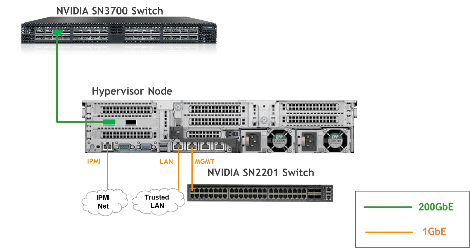
Wiring
Hypervisor Node
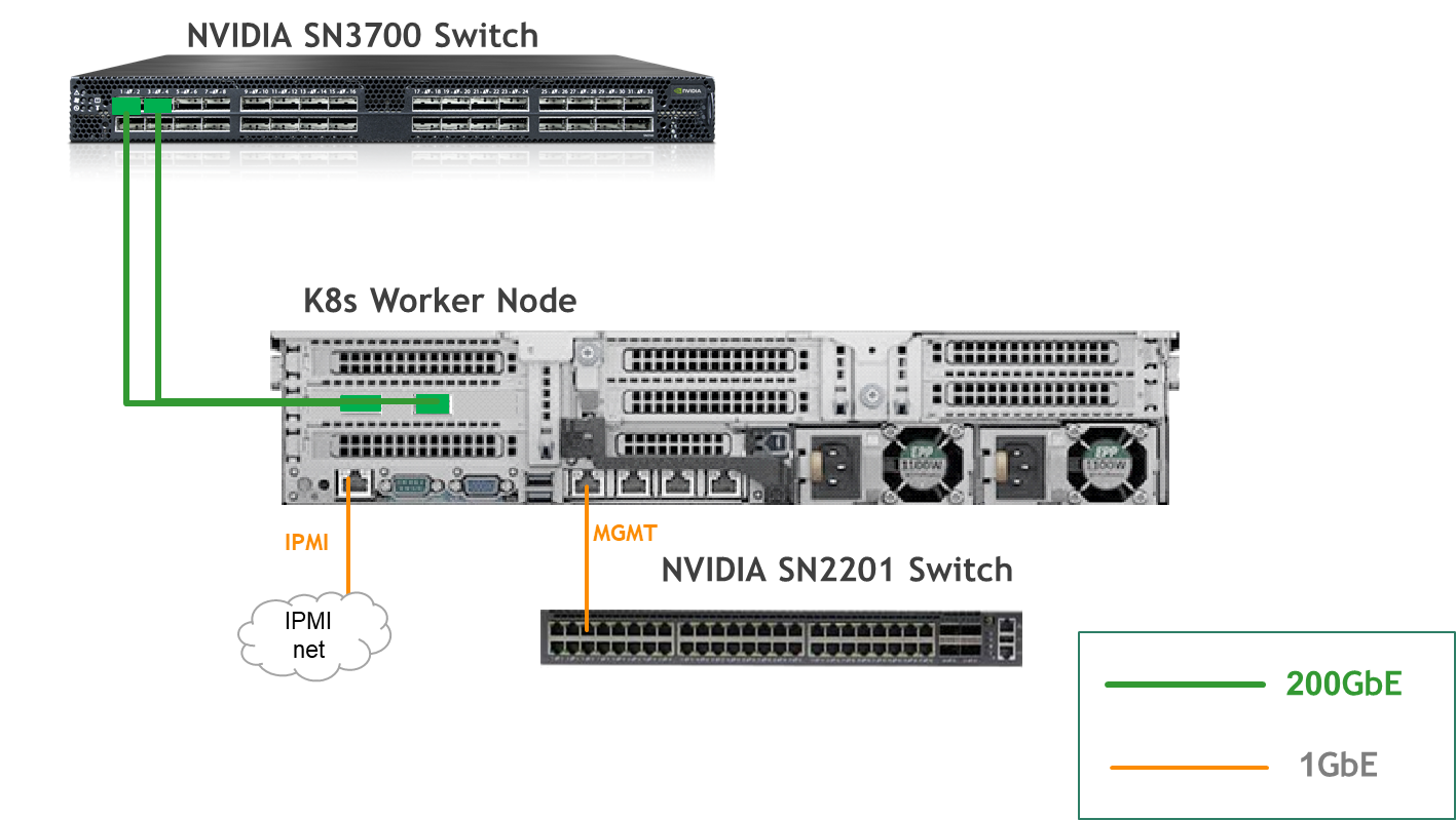
K8s Worker Node
Fabric Configuration
Updating Cumulus Linux
As a best practice, make sure to use the latest released Cumulus Linux NOS version.
For information on how to upgrade Cumulus Linux, refer to the Cumulus Linux User Guide.
Configuring the Cumulus Linux Switch
Configure the SN3700 switch (hs-switch) as follows:
-
The following commands configure BGP unnumbered on
hs-switch -
Cumulus Linux enables the BGP equal-cost multipathing (ECMP) option by default
Configure the SN2201 switch (mgmt-switch) as follows:
Host Configuration
Ensure that SR-IOV is enabled in the BIOS settings on the worker node servers, and that the servers are tuned for maximum performance.
Make sure all worker nodes have the same PCIe placement for the BlueField-3 NIC and that they show the same interface name.
Hypervisor Installation and Configuration
No change from the Baseline RDG (Section "Deployment and Configuration", Subsection "Prepare Infrastructure Servers") regarding Firewall VM, Jump VM, MaaS VM.
Provision Master VMs and Worker Nodes Using MaaS
Proceed with the instructions from the Baseline RDG until you reach the subsection "Deploy Master VMs using Cloud-Init".
Use the following cloud-init script instead of the one in the Baseline RDG to install the necessary software and also configure correct routing to the storage target node:
Master node cloud-init
#cloud-config
system_info:
  default_user:
    name: depuser
    passwd: "$6$jOKPZPHD9XbG72lJ$evCabLvy1GEZ5OR1Rrece3NhWpZ2CnS0E3fu5P1VcZgcRO37e4es9gmriyh14b8Jx8gmGwHAJxs3ZEjB0s0kn/"
    lock_passwd: false
    groups: [adm, audio, cdrom, dialout, dip, floppy, lxd, netdev, plugdev, sudo, video]
    sudo: ["ALL=(ALL) NOPASSWD:ALL"]
    shell: /bin/bash
ssh_pwauth: True
package_upgrade: true
runcmd:
    - apt-get update
    - apt-get -y install nfs-common
    - |
      cat <<'EOF' | tee /etc/netplan/99-static-route.yaml
      network:
        version: 2
        ethernets:
          enp1s0:
            routes:
              - to: 10.0.124.1
                via: 10.0.110.30
      EOF
    - netplan apply
After that proceed exactly as instructed in the Baseline RDG, and in addition to the verification commands mentioned there, run the following command to verify that the static route has been configured correctly:
Master1 Console
root@master1:~# ip r
default via 10.0.110.254 dev enp1s0 proto static
10.0.110.0/24 dev enp1s0 proto kernel scope link src 10.0.110.1
10.0.124.1 via 10.0.110.30 dev enp1s0 proto static
No changes from the Baseline RDG to the worker nodes provisioning.
Storage Target Configuration
-
The Storage target node is a separate, manually configured node in this RDG.
-
It will be a VM running on the hypervisor, with ConnectX-7 NIC and NVMe SSD disk attached to it as PCIe devices using PCI passthrough.
Suggested specifications:
-
vCPU: 8
-
RAM: 32GB
-
Storage:
-
VirtIO disk of 60GB size
-
NVMe SSD of 1.7TB size
-
-
Network interface:
-
Bridge device, connected to
mgmt-br
-
Procedure:
-
Perform a regular Ubuntu 24.04 installation on the Storage target VM.
-
Create the following Netplan configuration to enable internet connectivity, DNS resolution and set an IP in the storage high-speed subnet:
Replace
enp1s0andenp5s0np1with your interface names.
Storage Target netplan
network: version: 2 ethernets: enp1s0: addresses: - "10.0.110.30/24" mtu: 9000 nameservers: addresses: - 10.0.110.252 search: - dpf.rdg.local.domain routes: - to: "default" via: "10.0.110.254" enp5s0np1: addresses: - "10.0.124.1/24" mtu: 9000 -
Apply the netplan configuration:Storage Target Console
sudo netplan apply -
Update and upgrade the system:Storage Target Console
sudo apt update -y
sudo apt upgrade -y
-
Create XFS file system on the NVMe disk and mount it on
/srv/nfsdirectory:Replace
/dev/nvme0n1with your device name.
Storage Target Console
sudo mkfs.xfs /dev/nvme0n1
sudo mkdir -m 777 /srv/nfs/
sudo mount /dev/nvme0n1 /srv/nfs/
-
Set the mount to be persistent:
Storage Target Console
$ sudo blkid
/dev/nvme0n1 /dev/nvme0n1: UUID="b37df0a9-d741-4222-82c9-7a3d66ffc0e1" BLOCK_SIZE="512" TYPE="xfs"

$ echo "/dev/disk/by-uuid/b37df0a9-d741-4222-82c9-7a3d66ffc0e1 /srv/nfs xfs defaults 0 1" | sudo tee -a /etc/fstab
-
Install and configure an NFS server with the
/srv/nfsdirectory:Storage Target Console
sudo apt install -y nfs-server
echo "/srv/nfs/ 10.0.110.0/24(rw,sync,no_subtree_check)" | sudo tee -a /etc/exports
echo "/srv/nfs/ 10.0.124.0/24(rw,sync,no_subtree_check)" | sudo tee -a /etc/exports
-
Restart the NFS server:
Storage Target Console
sudo systemctl restart nfs-server
-
Create the directory
shareunder/srv/nfswith the same permissions as the parent directory:Storage Target Console
sudo mkdir -m 777 /srv/nfs/share
K8s Cluster Deployment and Configuration
The procedures for initial Kubernetes cluster deployment using Kubespray for the master nodes, and subsequent verification, remain unchanged from the Baseline RDG (Section "K8s Cluster Deployment and Configuration", Subsections: "Kubespray Deployment and Configuration", "Deploying Cluster Using Kubespray Ansible Playbook","K8s Deployment Verification").
As in Baseline RDG, Worker nodes are added later, after DPF and prerequisite components are installed.
DPF Installation
Software Prerequisites and Required Variables
Refer to the Baseline RDG (Section "DPF Installation", Subsection "Software Prerequisites and Required Variables") for software prerequisites (like helm, envsubst).
Proceed to clone the doca-platform Git repository (and make sure to use tag v25.10.0):
Jump Node Console
git clone https://github.com/NVIDIA/doca-platform.git
cd doca-platform
git checkout v25.10.0
Change to the directory containing the hbn-snap readme.md, as all commands will be run from this location:
Jump Node Console
$ cd docs/public/user-guides/host-trusted/use-cases/hbn-snap
Edit the following file to define the required variables for the installation:
-
Replace the values for the variables in the following file with the values that fit your setup.
Specifically, pay attention toDPU_P0,DPUCLUSTER_INTERFACEand to DPU_P0_PF_NAME, DPU_P1_PF_NAME, DPU_P0_VF10_NAME, DPU_P1_VF10_NAME
manifests/00-env-vars/envvars.env
## Virtual IP used by the load balancer for the DPU Cluster. Must be a reserved IP from the management subnet and not allocated by DHCP.
export DPUCLUSTER_VIP=10.0.110.200

## Interface on which the DPUCluster load balancer will listen. Should be the management interface of the control plane node.
export DPUCLUSTER_INTERFACE=enp1s0

## IP address of the NFS server used for storing the BFB image.
## NOTE: This environment variable does NOT control the address of the NFS server used as a remote target by SNAP VirtioFS.
export NFS_SERVER_IP=10.0.110.253

## The repository URL for the NVIDIA Helm chart registry.
## Usually this is the NVIDIA Helm NGC registry. For development purposes, this can be set to a different repository.
export HELM_REGISTRY_REPO_URL=https://helm.ngc.nvidia.com/nvidia/doca

## The repository URL for the HBN container image.
## Usually this is the NVIDIA NGC registry. For development purposes, this can be set to a different repository.
export HBN_NGC_IMAGE_URL=nvcr.io/nvidia/doca/doca_hbn

## The repository URL for the SNAP VFS container image.
## Usually this is the NVIDIA NGC registry. For development purposes, this can be set to a different repository.
export SNAP_NGC_IMAGE_URL=nvcr.io/nvidia/doca/doca_vfs

## The DPF REGISTRY is the Helm repository URL where the DPF Operator Chart resides.
## Usually this is the NVIDIA Helm NGC registry. For development purposes, this can be set to a different repository.
export REGISTRY=https://helm.ngc.nvidia.com/nvidia/doca

## The DPF TAG is the version of the DPF components which will be deployed in this guide.
export TAG=v25.10.0

## URL to the BFB used in the `bfb.yaml` and linked by the DPUSet.
export BFB_URL="https://content.mellanox.com/BlueField/BFBs/Ubuntu24.04/bf-bundle-3.2.1-34_25.11_ubuntu-24.04_64k_prod.bfb"

# contains the name of the network PF 0 on the host side, e.g. enp8s0f0np0
export DPU_P0_PF_NAME=ens4f0
# contains the name of the network PF 1 on the host side, e.g. enp8s0f1np1
export DPU_P1_PF_NAME=ens4f1
# contains the name of the network VF 10 on P0 on the host side, e.g. enp8s0f0v10
export DPU_P0_VF10_NAME=ens4f0v10
# contains the name of the network VF 10 on P1 on the host side, e.g. enp8s0f1v10
export DPU_P1_VF10_NAME=ens4f1v10
Export environment variables for the installation:
Jump Node Console
source manifests/00-env-vars/envvars.env
DPF Operator Installation
No change from the Baseline RDG (Section "DPF Installation", Subsection "DPF Operator Installation").
DPF System Installation
No change from the Baseline RDG (Section "DPF Installation", Subsection "DPF System Installation").
Install components to enable Accelerated Interfaces
Please perform this step from the Baseline RDG (Section "DPF Installation", Subsection "Install Components to enable Accelerated Interfaces").
Note that sriov_network_operator_policy.yaml is not applied at this time and will be applied later on...
DPU Deployment Installation
Before deploying the objects under manifests/04.2-dpudeployment-installation-virtiofs/directory, a few adjustments are needed to achieve better performance results.
Edit the DPUFlavor YAML to add the NUM_VF_MSIX firmware paramater and increase the hugepages value in the grub:
The parameter NUM_VF_MSIX is set to 48 in the provided example, which is suitable for the servers used in this RDG.
Set this value to match the physical number of cores in the NUMA node where the NIC is located.
The rest of the configuration files remain the same, you would need to apply the following command:
Jump Node Console
cat manifests/04.2-dpudeployment-installation-virtiofs/*.yaml | envsubst | kubectl apply -f -
It will apply all the YAMLs required for the deployment - DPUDeployment, BFB, DPUFlavor, Service Templates and Configurations for the various DPU Services (7 separate service modules for SNAP and one for HBN), Physical Interfaces definitions and IPAM definitions.
Please proceed as described in the Baseline RDG until "Infrastructure Latency & Bandwidth Validation" section, including the cluster scale-out (adding the worker nodes).
Note that the first validation command after applying the above command should be (instead of the first command that appears in the Baseline RDG):
Jump Node Console
kubectl wait --for=condition=ApplicationsReconciled --namespace dpf-operator-system dpuservices -l svc.dpu.nvidia.com/owned-by-dpudeployment=dpf-operator-system_hbn-snap
Testing Storage & Network Connectivity
In the the next steps, we will configure and test the Virtio-FS storage and the accelerated network connection.
This will create the SriovNetworkNodePolicy and NetworkAttachmentDefinition objects:
Jump Node Console
cat manifests/05-network-configuration/*.yaml | envsubst | kubectl apply -f -
And this will create the test pods:
For achieving maximum TCP performance, please edit the pods in test-hostdev-pods.yaml to use 24 cores instead of 16
Jump Node Console
kubectl apply -f manifests/06-network-test/test-hostdev-pods.yaml
iPerf TCP Bandwidth Test
Connect to the first pod:
Jump Node Console
$ kubectl exec -it sriov-hostdev-pf0vf10-test-worker1-5bccdc4c75-97xms -- bash
Before starting the iperf3 server listeners, and to achieve good results, check which cores the pod is currently running on in another tab:
Jump Node Console
$ ssh worker1
depuser@worker1:~$ sudo -i
root@worker1:~# crictl ps | grep sriov-hostdev-pf0vf10
a4441f76405cf       0ac86781a84f1       14 minutes ago      Running             nginx                         0                   24f4c327d918f       sriov-hostdev-pf0vf10-test-worker1-5bccdc4c75-97xms   default

root@worker1:~# crictl inspect a4441f76405cf | jq '.status.resources.linux.cpusetCpus'
"28-51"
Back in the first pod - use vim to create the following script to start multiple iperf3 servers (1 for each core) on different ports:
iperf_server.sh
#!/bin/bash

# Cores to bind the iperf3 server processes to
CORES=$1

# Function to expand core ranges (e.g., "10-20,40-50" -> array of individual cores)
expand_core_ranges() {
    local ranges=$1
    local cores=()

    # Split by comma to handle multiple ranges
    IFS=',' read -ra RANGE_ARRAY <<< "$ranges"

    for range in "${RANGE_ARRAY[@]}"; do
        # Check if it's a range (contains '-') or a single core
        if [[ $range == *"-"* ]]; then
            first=$(echo $range | cut -d "-" -f1)
            last=$(echo $range | cut -d "-" -f2)
            for core in $(seq $first $last); do
                cores+=($core)
            done
        else
            cores+=($range)
        fi
    done

    echo "${cores[@]}"
}

# Expand the core ranges into an array
core_array=($(expand_core_ranges "$CORES"))
ports_num=${#core_array[@]}

echo "Starting $ports_num iperf3 server processes on cores: ${core_array[@]}"

# Loop over each core and run iperf3 servers with sequential port assignment
for i in $(seq 1 $ports_num); do
   core=${core_array[$((i-1))]}
   port=$((5201 + i * 2))
   echo "Running iperf3 server $i on core $core, port $port"
   taskset -c $core iperf3 -s -p $port > /dev/null 2>&1 &
done
For best performance please set 9K MTU on the net1 interface and then start the script using the previous CPU range (leave 1 core as a buffer):
First Pod Console
root@sriov-hostdev-pf0vf10-test-worker1-5bccdc4c75-97xms:/# ip link set net1 mtu 9000
root@sriov-hostdev-pf0vf10-test-worker1-5bccdc4c75-97xms:/# chmod +x iperf_server.sh
root@sriov-hostdev-pf0vf10-test-worker1-5bccdc4c75-97xms:/# ./iperf_server.sh 28-51
Starting 16 iperf3 server processes on cores: 28 29 30 31 32 33 34 35 36 37 38 39 40 41 42 43 44 45 46 47 48 49 50 51
Running iperf3 server 1
Running iperf3 server 2
...
...
Running iperf3 server 23
Running iperf3 server 24

root@sriov-hostdev-pf0vf10-test-worker1-5bccdc4c75-97xms:/# ps -ef | grep iperf3
   38 root      0:00 iperf3 -s -p 5203
   39 root      0:00 iperf3 -s -p 5205
...
...
   60 root      0:27 iperf3 -s -p 5247
   61 root      0:40 iperf3 -s -p 5249
Connect to the second pod:
Jump Node Console
$ kubectl exec -it sriov-hostdev-pf0vf10-test-worker2-85b7cb76fd-qmljl -- bash
Follow the previously displayed method to identify the CPU cores that the second pod is running on. In our case it was the same range (28-51).
Use vim to create the following script to start multiple iperf3 clients that will connect to each iperf3 server in the first pod:
-
The script receives 3 parameters: the server IP to connect to, the CPU cores on which to spawn the
iperf3processes, and the duration theiperf3test. Make sure to provide all 3 when initiating the script and providing the CPU cores as a range (28-51).
iperf_client.sh
#!/bin/bash

# IP address of the server where iperf3 servers are running
SERVER_IP=$1  # Change to your server's IP

# Cores to bind the iperf3 client processes to
CORES=$2

# Duration to run the iperf3 test
DUR=$3

# Variable to accumulate the total bandwidth in Gbit/sec
total_bandwidth_Gbit=0

# Function to expand core ranges (e.g., "10-20,40-50" -> array of individual cores)
expand_core_ranges() {
    local ranges=$1
    local cores=()

    # Split by comma to handle multiple ranges
    IFS=',' read -ra RANGE_ARRAY <<< "$ranges"

    for range in "${RANGE_ARRAY[@]}"; do
        # Check if it's a range (contains '-') or a single core
        if [[ $range == *"-"* ]]; then
            first=$(echo $range | cut -d "-" -f1)
            last=$(echo $range | cut -d "-" -f2)
            for core in $(seq $first $last); do
                cores+=($core)
            done
        else
            cores+=($range)
        fi
    done

    echo "${cores[@]}"
}

# Expand the core ranges into an array
core_array=($(expand_core_ranges "$CORES"))
ports_num=${#core_array[@]}

echo "Starting $ports_num iperf3 client processes on cores: ${core_array[@]}"

# Array to store the PIDs of background tasks
pids=()

# Loop over each core and run iperf3 clients with sequential port assignment
for i in $(seq 1 $ports_num); do
    port=$((5201 + i * 2))
    cpu_core=${core_array[$((i-1))]}  # Assign CPU core from the expanded array
    output_file="iperf3_client_results_$port.log"

    echo "Running iperf3 client $i on core $cpu_core, connecting to port $port"
    # Run the iperf3 client in the background with CPU core binding
    timeout $(( DUR +5 )) taskset -c $cpu_core iperf3 -Z -c $SERVER_IP -p $port -t $DUR -J > $output_file &
    pid=$!
    pids+=("$pid")
done

# Wait for all background tasks to complete and check their status
for pid in "${pids[@]}"; do
    wait $pid
    if [[ $? -ne 0 ]]; then
        echo "Process with PID $pid failed or timed out."
    fi
done

# Summarize the results from each log file
echo "Summary of iperf3 client results:"
for i in $(seq 1 $ports_num); do
    port=$((5201 + i * 2))
    output_file="iperf3_client_results_$port.log"

    if [[ -f $output_file ]]; then
        echo "Results for port $port:"

        # Parse the results and print a summary
        bandwidth_bps=$(jq '.end.sum_received.bits_per_second' $output_file)

        if [[ -n $bandwidth_bps ]]; then
           # Convert bandwidth from bps to Gbit/sec
           bandwidth_Gbit=$(echo "scale=3; $bandwidth_bps / 1000000000" | bc)
           echo "  Bandwidth: $bandwidth_Gbit Gbit/sec"

           # Accumulate the bandwidth for the total summary
           total_bandwidth_Gbit=$(echo "scale=3; $total_bandwidth_Gbit + $bandwidth_Gbit" | bc)

           # Delete current log file
           rm $output_file
        else
           echo "No bandwidth data found in $output_file"
        fi

    else
        echo "No results found for port $port"
    fi
done

# Print the total bandwidth summary
echo "Total Bandwidth across all streams: $total_bandwidth_Gbit Gbit/sec"
Again, please set 9K MTU on net1 for maximum performance and run the script to check the performance results:
Second Pod Console
root@sriov-hostdev-pf0vf10-test-worker2-85b7cb76fd-qmljl:/# ip link set net1 mtu 9000
root@sriov-hostdev-pf0vf10-test-worker2-85b7cb76fd-qmljl:/# chmod +x iperf_client.sh
root@sriov-hostdev-pf0vf10-test-worker2-85b7cb76fd-qmljl:/# ./iperf_client.sh 10.0.121.1 28-51 30

Summary of iperf3 client results:
Results for port 5203:
  Bandwidth: 14.207 Gbit/sec
Results for port 5205:
  Bandwidth: 22.445 Gbit/sec
Results for port 5207:
  Bandwidth: 8.868 Gbit/sec
Results for port 5209:
  Bandwidth: 11.115 Gbit/sec
Results for port 5211:
  Bandwidth: 14.104 Gbit/sec
Results for port 5213:
  Bandwidth: 13.387 Gbit/sec
Results for port 5215:
  Bandwidth: 22.743 Gbit/sec
Results for port 5217:
  Bandwidth: 12.132 Gbit/sec
Results for port 5219:
  Bandwidth: 13.927 Gbit/sec
Results for port 5221:
  Bandwidth: 13.470 Gbit/sec
Results for port 5223:
  Bandwidth: 22.720 Gbit/sec
Results for port 5225:
  Bandwidth: 14.771 Gbit/sec
Results for port 5227:
  Bandwidth: 12.752 Gbit/sec
Results for port 5229:
  Bandwidth: 9.174 Gbit/sec
Results for port 5231:
  Bandwidth: 14.265 Gbit/sec
Results for port 5233:
  Bandwidth: 24.338 Gbit/sec
Results for port 5235:
  Bandwidth: 14.087 Gbit/sec
Results for port 5237:
  Bandwidth: 13.353 Gbit/sec
Results for port 5239:
  Bandwidth: 14.555 Gbit/sec
Results for port 5241:
  Bandwidth: 20.808 Gbit/sec
Results for port 5243:
  Bandwidth: 13.056 Gbit/sec
Results for port 5245:
  Bandwidth: 16.648 Gbit/sec
Results for port 5247:
  Bandwidth: 17.545 Gbit/sec
Results for port 5249:
  Bandwidth: 20.905 Gbit/sec
Total Bandwidth across all streams: 375.375 Gbit/sec
Storage Test
The following command will define the DPUStorageVendor for NFS CSI and the DPUStoragePolicy for filesystem policy:
Jump Node Console
cat manifests/07.2-storage-configuration-virtiofs/*.yaml | envsubst | kubectl apply -f -
Verify the DPUStorageVendor and DPUStoragePolicy objects are ready:
Jump Node Console
kubectl wait --for=condition=Ready --namespace dpf-operator-system dpustoragevendors --all
kubectl wait --for=condition=Ready --namespace dpf-operator-system dpustoragepolicies --all
Deploy storage test pods that mount a storage volume provided by SNAP VirtioFS:
Jump Node Console
kubectl apply -f manifests/08.2-storage-test-virtiofs
Check the virtiofs-tag name:
Jump Node Console
$ kubectl get dpuvolumeattachments.storage.dpu.nvidia.com -A -o json | jq '.items[0].status.dpu.virtioFSAttrs.filesystemTag'
"3e76e376579383d2tag"
Connect to the test pod, validate that the virtiofs filesystem is mounted with the previous tag name and install the fio software:
Jump Node Console
$ kubectl exec -it storage-test-pod-virtiofs-hotplug-pf-0 -- bash

root@storage-test-pod-virtiofs-hotplug-pf-0:/# df -Th
Filesystem          Type      Size  Used Avail Use% Mounted on
overlay             overlay   439G   17G  400G   4% /
tmpfs               tmpfs      64M     0   64M   0% /dev
3e76e376579383d2tag virtiofs  1.8T   45G  1.8T   3% /mnt/vol1
/dev/nvme0n1p2      ext4      439G   17G  400G   4% /etc/hosts
shm                 tmpfs      64M     0   64M   0% /dev/shm
tmpfs               tmpfs     251G   12K  251G   1% /run/secrets/kubernetes.io/serviceaccount
tmpfs               tmpfs     126G     0  126G   0% /proc/acpi
tmpfs               tmpfs     126G     0  126G   0% /proc/scsi
tmpfs               tmpfs     126G     0  126G   0% /sys/firmware
tmpfs               tmpfs     126G     0  126G   0% /sys/devices/virtual/powercap

root@storage-test-pod-virtiofs-hotplug-pf-0:/# apt update && apt install -y vim fio
Using vim, create the following file:
job-4k.fio
[global]
ioengine=libaio
direct=1
iodepth=32
rw=read
bs=4k
size=1G
numjobs=8
runtime=60
time_based
group_reporting

[job1]
filename=/mnt/vol1/test.fio
Finally, run the fio test:
Jump Node Console
root@storage-test-pod-virtiofs-hotplug-pf-0:/# fio job-4k.fio
job1: (g=0): rw=read, bs=4K-4K/4K-4K/4K-4K, ioengine=libaio, iodepth=32
...
fio-2.2.10
...
...
Starting 8 processes
job1: Laying out IO file(s) (1 file(s) / 1024MB)
Jobs: 8 (f=8): [R(8)] [100.0% done] [826.1MB/0KB/0KB /s] [212K/0/0 iops] [eta 00m:00s]
job1: (groupid=0, jobs=8): err= 0: pid=1183: Mon Dec  1 10:31:32 2025
  read : io=47664MB, bw=813351KB/s, iops=203337, runt= 60008msec
    slat (usec): min=0, max=679, avg= 6.90, stdev= 4.13
    clat (usec): min=167, max=135036, avg=1250.42, stdev=4941.25
     lat (usec): min=170, max=135038, avg=1257.36, stdev=4940.79
    clat percentiles (usec):
     |  1.00th=[  258],  5.00th=[  278], 10.00th=[  286], 20.00th=[  298],
     | 30.00th=[  302], 40.00th=[  310], 50.00th=[  314], 60.00th=[  322],
     | 70.00th=[  326], 80.00th=[  338], 90.00th=[  358], 95.00th=[  470],
     | 99.00th=[27520], 99.50th=[32128], 99.90th=[46336], 99.95th=[52992],
     | 99.99th=[68096]
    bw (KB  /s): min=85832, max=121912, per=12.51%, avg=101789.00, stdev=5105.93
    lat (usec) : 250=0.39%, 500=95.22%, 750=0.55%, 1000=0.01%
    lat (msec) : 2=0.01%, 4=0.01%, 10=0.01%, 20=1.05%, 50=2.70%
    lat (msec) : 100=0.07%, 250=0.01%
  cpu          : usr=2.78%, sys=24.20%, ctx=8652632, majf=0, minf=340
  IO depths    : 1=0.1%, 2=0.1%, 4=0.1%, 8=0.1%, 16=0.1%, 32=100.0%, >=64=0.0%
     submit    : 0=0.0%, 4=100.0%, 8=0.0%, 16=0.0%, 32=0.0%, 64=0.0%, >=64=0.0%
     complete  : 0=0.0%, 4=100.0%, 8=0.0%, 16=0.0%, 32=0.1%, 64=0.0%, >=64=0.0%
     issued    : total=r=12201896/w=0/d=0, short=r=0/w=0/d=0, drop=r=0/w=0/d=0
     latency   : target=0, window=0, percentile=100.00%, depth=32

Run status group 0 (all jobs):
   READ: io=47664MB, aggrb=813351KB/s, minb=813351KB/s, maxb=813351KB/s, mint=60008msec, maxt=60008msec
Done!
Authors

|
Guy Zilberman Guy Zilberman is a solution architect at NVIDIA's Networking Solutions Labs, bringing extensive experience from several leadership roles in cloud computing.
|

|
Shachar Dor Shachar Dor joined the Solutions Lab team after working more than ten years as a software architect at NVIDIA Networking (previously Mellanox Technologies), where he was responsible for the architecture of network management products and solutions. Shachar's focus is on networking technologies, especially around fabric bring-up, configuration, monitoring, and life-cycle management. |
NVIDIA and the NVIDIA logo, are trademarks and/or registered trademarks of NVIDIA Corporation in the U.S. and other countries. Other company and product names may be trademarks of the respective companies with which they are associated.™
2025 NVIDIA Corporation. All rights reserved.©
Last updated: