Created on July 6, 2026
Scope
This Reference Deployment Guide (RDG) provides detailed instructions for deploying a Kubernetes (K8s) cluster using NVIDIA® BlueField®-3 DPUs and DOCA Platform Framework (DPF) in Host Trusted mode. The guide covers setting up accelerated OVN-Kubernetes, Host-Based Networking (HBN) services, and additional services on NVIDIA® BlueField®-3 DPUs.
As a reference implementation, this guide focuses on using open-source components and outlines the entire deployment process, including bare metal and virtual machine provisioning with KVM virtualization and MaaS. It also addresses performance tuning to achieve optimal results.
Leveraging NVIDIA's DPF, administrators can provision and manage DPU resources within a Kubernetes cluster while deploying and orchestrating HBN and accelerated OVN-Kubernetes services. This approach enables full utilization of NVIDIA DPU hardware acceleration and offloading capabilities, maximizing data center workload efficiency and performance.
This guide is designed for experienced system administrators, system engineers, and solution architects who seek to deploy high-performance Kubernetes clusters and enable NVIDIA BlueField DPUs.
-
This reference implementation, as the name implies, is a specific, opinionated deployment example designed to address the use case described above.
-
While other approaches may exist to implement similar solutions, this document provides a detailed guide for this particular method.
Abbreviations and Acronyms
|
Term |
Definition |
Term |
Definition |
|---|---|---|---|
|
BFB |
BlueField Bootstream |
K8S |
Kubernetes |
|
BGP |
Border Gateway Protocol |
MAAS |
Metal as a Service |
|
CNI |
Container Network Interface |
OVN |
Open Virtual Network |
|
CSI |
Container Storage Interface |
RDG |
Reference Deployment Guide |
|
DOCA |
Data Center Infrastructure-on-a-Chip Architecture |
RDMA |
Remote Direct Memory Access |
|
DPF |
DOCA Platform Framework |
SFC |
Service Function Chaining |
|
DPU |
Data Processing Unit |
SR-IOV |
Single Root Input/Output Virtualization |
|
DTS |
DOCA Telemetry Service |
TOR |
Top of Rack |
|
GENEVE |
Generic Network Virtualization Encapsulation |
VLAN |
Virtual LAN (Local Area Network) |
|
HBN |
Host Based Networking |
VRR |
Virtual Router Redundancy |
|
IPAM |
IP Address Management |
VTEP |
Virtual Tunnel End Point |
Introduction
The NVIDIA BlueField-3 data processing unit (DPU) is a 400 Gb/s infrastructure compute platform designed for line-rate processing of software-defined networking, storage, and cybersecurity. BlueField-3 combines powerful computing, high-speed networking, and extensive programmability to deliver hardware-accelerated, software-defined solutions for demanding workloads.
NVIDIA DOCA unlocks the full potential of the NVIDIA BlueField platform, enabling rapid development of applications and services that offload, accelerate, and isolate data center workloads.
Host-based Networking (HBN) is a DOCA service that allows network architects to design networks based on layer-3 (L3) protocols. HBN enables routing to run on the server side by using BlueField as a BGP router. The HBN solution encapsulates a set of network functions inside a container, which is deployed as a service pod on BlueField's Arm cores.
OVN-Kubernetes is a Kubernetes CNI network plugin that provides robust networking for Kubernetes clusters. Built on Open Virtual Network (OVN) and Open vSwitch (OVS), it supports hardware acceleration to offload OVS packet processing to NIC/DPU hardware. With OVS-DOCA, an extension of traditional OVS-DPDK and OVS-Kernel, accelerated OVN-Kubernetes delivers industry-leading performance, functionality, and efficiency. Running OVN-Kubernetes on the DPU reserves host CPUs exclusively for workloads, maximizing system resources.
Deploying and managing DPUs and their associated DOCA services—especially at scale—can be challenging. Without a provisioning and orchestration system, the complexity of managing the DPU lifecycle, deploying DOCA services, and providing the necessary network configuration on the DPU to redirect the network traffic via those services (service function chaining, or SFC) becomes a significant burden for cluster and system administrators; which is where the DOCA Platform Framework (DPF) comes into play.
DPF simplifies DPU management by providing orchestration through a Kubernetes API. It handles the provisioning and lifecycle management of DPUs, orchestrates specialized DPU services, and automates tasks such as service function chaining (SFC). This ensures seamless deployment of DOCA services like OVN-Kubernetes and HBN, allowing traffic to be efficiently offloaded and routed through HBN's data plane.
With DPF, users can efficiently manage and scale DPUs within their clusters while automating critical processes. DPF orchestrates the deployment of OVN-Kubernetes and HBN, optimizing performance with features such as offloaded OVN-Kubernetes CNI and accelerated traffic routing through HBN.
This RDG provides a comprehensive, practical example of installing the DPF system on a Kubernetes cluster. It also demonstrates performance optimizations, including Jumbo frame implementation, with results validated through standard RDMA and TCP workload tests.
References
Solution Architecture
Key Components and Technologies
-
NVIDIA BlueField® Data Processing Unit (DPU)
The NVIDIA® BlueField® data processing unit (DPU) ignites unprecedented innovation for modern data centers and supercomputing clusters. With its robust compute power and integrated software-defined hardware accelerators for networking, storage, and security, BlueField creates a secure and accelerated infrastructure for any workload in any environment, ushering in a new era of accelerated computing and AI.
-
NVIDIA DOCA Software Framework
NVIDIA DOCA™ unlocks the potential of the NVIDIA® BlueField® networking platform. By harnessing the power of BlueField DPUs and SuperNICs, DOCA enables the rapid creation of applications and services that offload, accelerate, and isolate data center workloads. It lets developers create software-defined, cloud-native, DPU- and SuperNIC-accelerated services with zero-trust protection, addressing the performance and security demands of modern data centers.
-
NVIDIA ConnectX SmartNICs
10/25/40/50/100/200 and 400G Ethernet Network Adapters
The industry-leading NVIDIA® ConnectX® family of smart network interface cards (SmartNICs) offer advanced hardware offloads and accelerations.
NVIDIA Ethernet adapters enable the highest ROI and lowest Total Cost of Ownership for hyperscale, public and private clouds, storage, machine learning, AI, big data, and telco platforms.
-
NVIDIA LinkX Cables
The NVIDIA® LinkX® product family of cables and transceivers provides the industry’s most complete line of 10, 25, 40, 50, 100, 200, and 400GbE in Ethernet and 100, 200 and 400Gb/s InfiniBand products for Cloud, HPC, hyperscale, Enterprise, telco, storage and artificial intelligence, data center applications.
-
NVIDIA Spectrum Ethernet Switches
Flexible form-factors with 16 to 128 physical ports, supporting 1GbE through 400GbE speeds.
Based on a ground-breaking silicon technology optimized for performance and scalability, NVIDIA Spectrum switches are ideal for building high-performance, cost-effective, and efficient Cloud Data Center Networks, Ethernet Storage Fabric, and Deep Learning Interconnects.
NVIDIA combines the benefits of NVIDIA Spectrum™ switches, based on an industry-leading application-specific integrated circuit (ASIC) technology, with a wide variety of modern network operating system choices, including NVIDIA Cumulus® Linux, SONiC and NVIDIA Onyx®.
-
NVIDIA Cumulus Linux
NVIDIA® Cumulus® Linux is the industry's most innovative open network operating system that allows you to automate, customize, and scale your data center network like no other.
-
NVIDIA Network Operator
The NVIDIA Network Operator simplifies the provisioning and management of NVIDIA networking resources in a Kubernetes cluster. The operator automatically installs the required host networking software - bringing together all the needed components to provide high-speed network connectivity. These components include the NVIDIA networking driver, Kubernetes device plugin, CNI plugins, IP address management (IPAM) plugin and others. The NVIDIA Network Operator works in conjunction with the NVIDIA GPU Operator to deliver high-throughput, low-latency networking for scale-out, GPU computing clusters.
-
Kubernetes
Kubernetes is an open-source container orchestration platform for deployment automation, scaling, and management of containerized applications.
-
Kubespray
Kubespray is a composition of Ansible playbooks, inventory, provisioning tools, and domain knowledge for generic OS/Kubernetes clusters configuration management tasks and provides:-
A highly available cluster
-
Composable attributes
-
Support for most popular Linux distributions
-
-
OVN-Kubernetes
OVN-Kubernetes (Open Virtual Networking - Kubernetes) is an open-source project that provides a robust networking solution for Kubernetes clusters with OVN (Open Virtual Networking) and Open vSwitch (Open Virtual Switch) at its core. It is a Kubernetes networking conformant plugin written according to the CNI (Container Network Interface) specifications.
-
RDMA
RDMA is a technology that allows computers in a network to exchange data without involving the processor, cache or operating system of either computer.
Like locally based DMA, RDMA improves throughput and performance and frees up compute resources.
Solution Design
Solution Logical Design
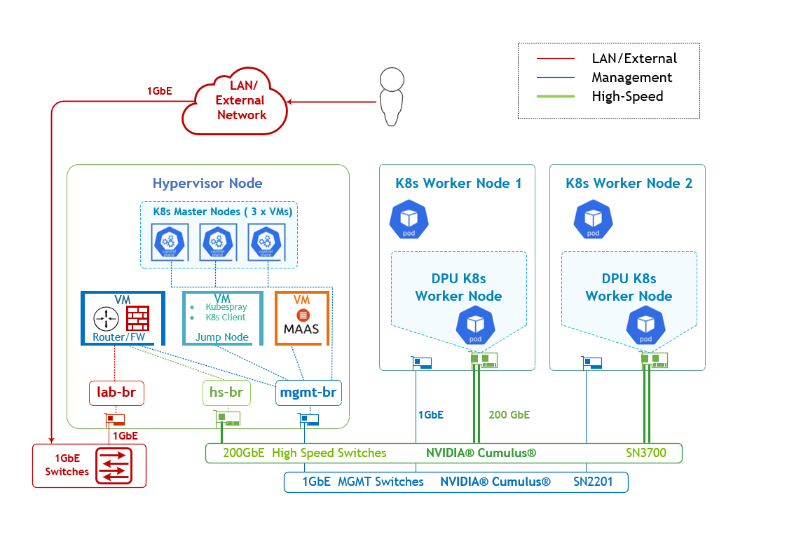
The logical design includes the following components:
-
1 x Hypervisor node (KVM based) with ConnectX-7
-
1 x Firewall VM
-
1 x Jump VM
-
1 x MaaS VM
-
3 x K8s Master VMs running all K8s management components
-
-
2 x Worker nodes (PCI Gen5), each with a 1 x BlueField-3 NIC
-
Single High-Speed (HS) switch, 1 x L3 HS underlay network
-
1 Gb Host Management network
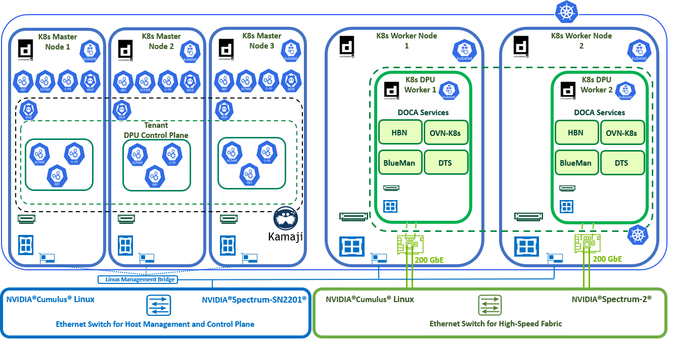
K8s Cluster Logical Design
The following K8s logical design illustration demonstrates the main components of the DPF system, among them:
-
3 x K8s Master VMs running all K8s management components
-
2 x K8s Worker nodes (x86)
-
2 x K8s DPU Workers running DOCA services (OVN-K8s, HBN, DTS, BlueMan)
-
1 x Kamaji (K8s Control-Plane Manager)
-
1 x DPU Control Plane (Tenant Cluster)
-
Connectivity to High-Speed/1Gb networks
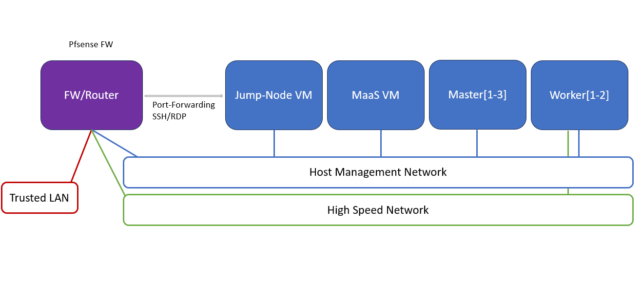
Firewall Design
The pfSense firewall in this solution serves a dual purpose:
-
Firewall – provides an isolated environment for the DPF system, ensuring secure operations
-
Router – enables internet access and connectivity between the host management network and the high-speed network
Port-forwarding rules for SSH and VNC are configured on the firewall to route traffic to the jump node’s IP address in the host management network. From the jump node, administrators can manage and access various devices in the setup, as well as handle the deployment of the Kubernetes (K8s) cluster and DPF components.
The following diagram illustrates the firewall design used in this solution:
Software Stack Components
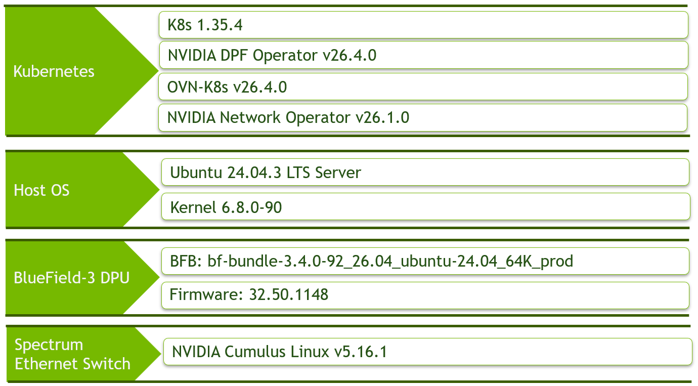
Make sure to use the exact same versions for the software stack as described above.
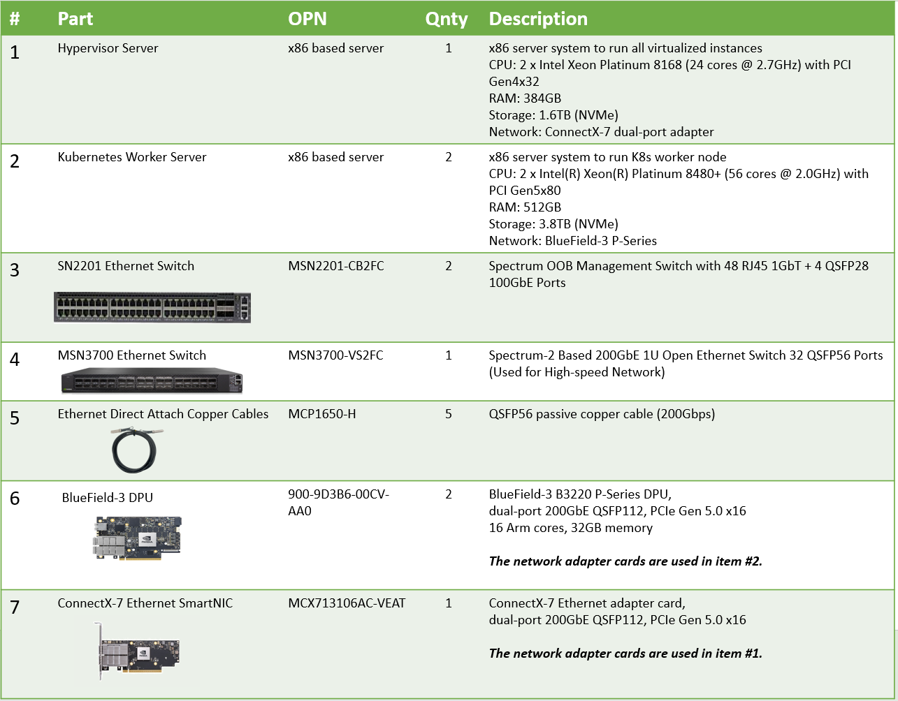
Bill of Materials
Deployment and Configuration
Node and Switch Definitions
These are the definitions and parameters used for deploying the demonstrated fabric:
|
Switch Port Usage |
||
|---|---|---|
|
Hostname |
Rack ID |
Ports |
|
|
1 |
swp1,11-14 |
|
|
1 |
swp1-3 |
|
Hosts |
|||||
|---|---|---|---|---|---|
|
Rack |
Server Type |
Server Name |
Switch Port |
IP and NICs |
Default Gateway |
|
Rack1
|
Hypervisor Node |
|
mgmt-switch: hs-switch: |
lab-br (interface eno1): Trusted LAN IP mgmt-br (interface eno2): - hs-br (interface ens2f0np0): - |
Trusted LAN GW |
|
Rack1
|
Worker Node |
|
mgmt-switch: hs-switch: |
ens15f0: 10.0.110.21/24 ens5f0np0/ens5f1np1: 10.0.120.0/22 |
10.0.110.254 |
|
Rack1
|
Worker Node |
|
mgmt-switch: hs-switch: |
ens15f0: 10.0.110.22/24 ens5f0np0/ens5f1np1: 10.0.120.0/22 |
10.0.110.254 |
|
Rack1 |
Firewall (Virtual) |
|
- |
WAN (lab-br): Trusted LAN IP LAN (mgmt-br): 10.0.110.254/24 OPT1 (hs-br): 172.169.50.1/30 |
Trusted LAN GW |
|
Rack1
|
Jump Node (Virtual) |
|
- |
enp1s0: 10.0.110.253/24 |
10.0.110.254 |
|
Rack1
|
MaaS (Virtual) |
|
- |
enp1s0: 10.0.110.252/24 |
10.0.110.254 |
|
Rack1
|
Master Node (Virtual) |
|
- |
enp1s0: 10.0.110.1/24 |
10.0.110.254 |
|
Rack1
|
Master Node (Virtual) |
|
- |
enp1s0: 10.0.110.2/24 |
10.0.110.254 |
|
Rack1
|
Master Node (Virtual) |
|
- |
enp1s0: 10.0.110.3/24 |
10.0.110.254 |
Wiring
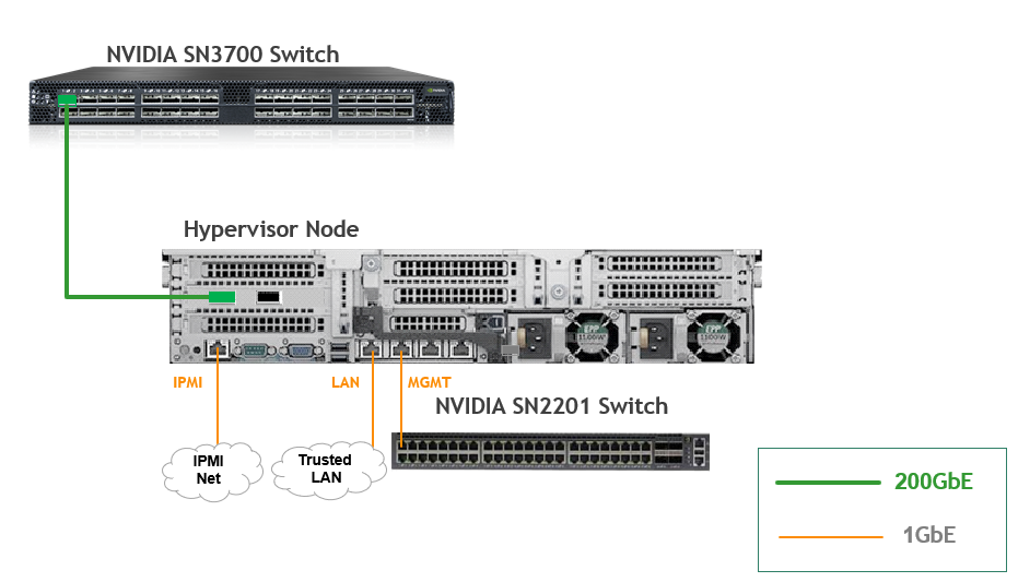
Hypervisor Node
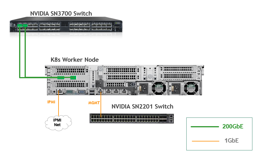
K8s Worker Node
Fabric Configuration
Updating Cumulus Linux
As a best practice, make sure to use the latest released Cumulus Linux NOS version.
For information on how to upgrade Cumulus Linux, refer to the Cumulus Linux User Guide.
Configuring the Cumulus Linux Switch
For the SN3700 switch (hs-switch), is configured as follows:
-
The following commands configure BGP unnumbered on
hs-switch. -
Cumulus Linux enables the BGP equal-cost multipathing (ECMP) option by default.
The SN2201 switch (mgmt-switch) is configured as follows:
Host Configuration
Make sure that the BIOS settings on the worker node servers have SR-IOV enabled and that the servers are tuned for maximum performance.
All worker nodes must have the same PCIe placement for the BlueField-3 NIC and must show the same interface name.
Hypervisor Installation and Configuration
The hypervisor used in this Reference Deployment Guide (RDG) is based on Ubuntu 24.04 with KVM.
While this document does not detail the KVM installation process, it is important to note that the setup requires the following ISOs to deploy the Firewall, Jump, and MaaS virtual machines (VMs):
-
Ubuntu 24.04
-
pfSense-CE-2.7.2
To implement the solution, three Linux bridges must be created on the hypervisor:
Ensure a DHCP record is configured for the lab-br bridge interface in your trusted LAN to assign it an IP address.
-
lab-br– connects the Firewall VM to the trusted LAN. -
mgmt-br– Connects the various VMs to the host management network. -
hs-br– Connects the Firewall VM to the high-speed network.
Additionally, an MTU of 9000 must be configured on the management and high-speed bridges (mgmt-br and hs-br) as well as their uplink interfaces to ensure optimal performance.
Hypervisor netplan configuration
network:
    ethernets:
        eno1:
            dhcp4: false
        eno2:
            dhcp4: false
            mtu: 9000
        ens2f0np0:
            dhcp4: false
            mtu: 9000
    bridges:
      lab-br:
         interfaces: [eno1]
         dhcp4: true
      mgmt-br:
         interfaces: [eno2]
         dhcp4: false
         mtu: 9000
      hs-br:
         interfaces: [ens2f0np0]
         dhcp4: false
         mtu: 9000
    version: 2
Apply the configuration:
Hypervisor Console
sudo netplan apply
Prepare Infrastructure Servers
Firewall VM - pfSense Installation and Interface Configuration
Download the pfSense CE (Community Edition) ISO to your hypervisor and proceed with the software installation.
Suggested spec:
-
vCPU: 2
-
RAM: 2GB
-
Storage: 10GB
-
Network interfaces
-
Bridge device connected to
lab-br -
Bridge device connected to
mgmt-br -
Bridge device connected to
hs-br
-
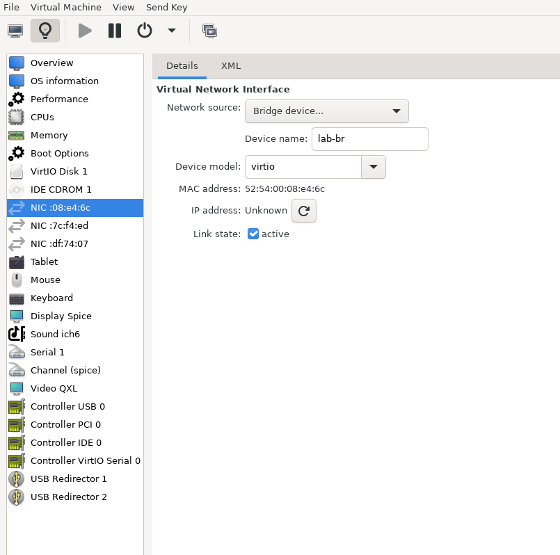
The Firewall VM must be connected to all three Linux bridges on the hypervisor. Before beginning the installation, ensure that three virtual network interfaces of type "Bridge device" are configured. Each interface should be connected to a different bridge (lab-br, mgmt-br, and hs-br) as illustrated in the diagram below.
After completing the installation, the setup wizard displays a menu with several options, such as "Assign Interfaces" and "Reboot System." During this phase, you must configure the network interfaces for the Firewall VM.
-
Select Option 2: "Set interface(s) IP address" and configure the interfaces as follows:
-
WAN (lab-br) – Trusted LAN IP (Static/DHCP)
-
LAN (mgmt-br) – Static IP
10.0.110.254/24 -
OPT1 (hs-br) – Static IP
172.169.50.1/30
-
-
Once the interface configuration is complete, use a web browser within the host management network to access the Firewall web interface and finalize the configuration.
Next, proceed with the installation of the Jump VM. This VM will serve as a platform for running a browser to access the Firewall’s web interface for post-installation configuration.
Jump VM
Suggested specifications:
-
vCPU: 4
-
RAM: 8GB
-
Storage: 25GB
-
Network interface: Bridge device, connected to
mgmt-br
Procedure:
-
Proceed with a standard Ubuntu 24.04 installation. Use the following login credentials across all hosts in this setup:
Username
Password
depuser
user
-
Enable internet connectivity and DNS resolution by creating the following Netplan configuration:
Use
10.0.110.254as a temporary DNS nameserver until the MaaS VM is installed and configured. After completing the MaaS installation, update the Netplan file to replace this address with the MaaS IP:10.0.110.252.
Jump Node netplan
YAMLnetwork: ethernets: enp1s0: dhcp4: false addresses: [10.0.110.253/24] nameservers: search: [dpf.rdg.local.domain] addresses: [10.0.110.254] routes: - to: default via: 10.0.110.254 version: 2 -
Apply the configuration:
Jump Node Console
depuser@jump:~$ sudo netplan apply -
Update and upgrade the system:
Jump Node Console
sudo apt update -y sudo apt upgrade -y -
Install TigerVNC and the Xfce desktop environment (for graphical access to the jump node via VNC):
Jump Node Console
sudo apt-get -y install tigervnc-standalone-server tigervnc-scraping-server tigervnc-tools xfce4 xfce4-goodies dbus-x11 echo "xfce4-session" | tee .xsession -
Set a VNC password for
depuser:Jump Node Console
vncpasswd -
Switch to
rootand create the TigerVNC user-to-display mapping at/etc/tigervnc/vncserver.users:Jump Node Console
sudo -i cat > /etc/tigervnc/vncserver.users << 'EOF' # TigerVNC User assignment # # This file assigns users to specific VNC display numbers. # The syntax is <display>=<username>. E.g.: # :1=depuser EOF -
Create the systemd unit
/etc/systemd/system/vncserver@.service:Jump Node Console
cat > /etc/systemd/system/vncserver@.service << 'EOF' [Unit] Description=Start TigerVNC server at startup After=syslog.target network.target [Service] Type=forking User=depuser Group=depuser WorkingDirectory=/home/depuser PIDFile=/home/depuser/.vnc/%H%i.pid ExecStartPre=-/usr/bin/vncserver -kill %i > /dev/null 2>&1 || : ExecStart=/usr/bin/vncserver -xstartup /usr/bin/startxfce4 -SecurityTypes VncAuth,TLSVnc -geometry 1920x1080 -localhost no -nolisten tcp %i ExecStop=/usr/bin/vncserver -kill %i > /dev/null 2>&1 || : [Install] WantedBy=multi-user.target EOF -
Enable and start the VNC service for display
:1(TigerVNC will listen on TCP port 5901):Jump Node Console
systemctl enable --now vncserver@:1.service systemctl status vncserver@:1.service -
Install Firefox for accessing the Firewall web interface:
Jump Node Console
sudo apt install -y firefox -
Generate an SSH key pair for
depuserin the jump node (later on will be imported to the admin user in MaaS to enable password-less login to the provisioned servers):Jump Node Console
depuser@jump:~$ ssh-keygen -t rsa -
Reboot the jump node to display the graphical user interface:
Jump Node Console
sudo rebootAfter setting up port-forwarding rules on the firewall (next steps), remote login to the graphical interface of the Jump node will be available.
Concurrent login to the local graphical console and using VNC isn't possible, make sure to first log out from the local console when switching to VNC connection.
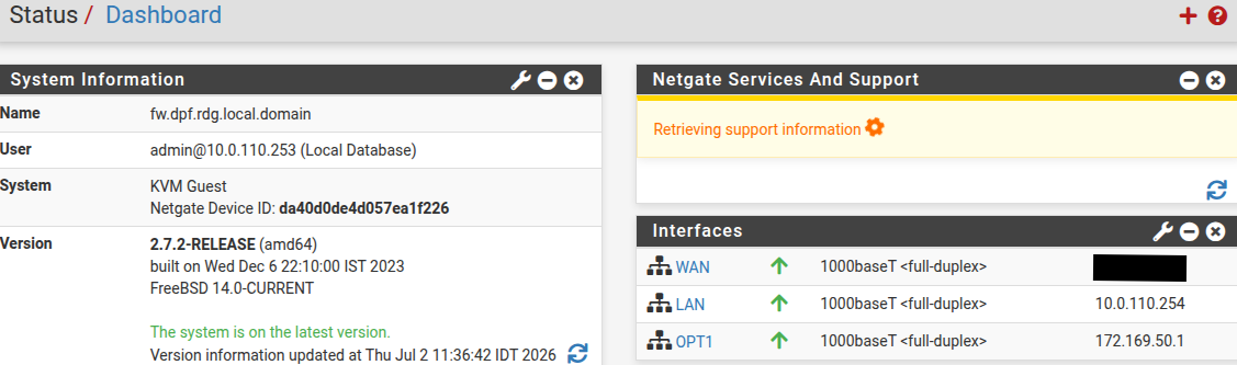
Firewall VM – Web Configuration
From your Jump node, open Firefox web browser and go to the pfSense web UI (http://10.0.110.254, default credentials are admin/pfsense). You should see a page similar to the following:
The IP addresses from the trusted LAN network under "DNS servers" and "Interfaces - WAN" are blurred.
Proceed with the following configurations:
The following screenshots display only a part of the configuration view. Make sure to not miss any of the steps mentioned below!
-
Interfaces
-
WAN – mark “Enable interface”, unmark “Block private networks and loopback addresses”
-
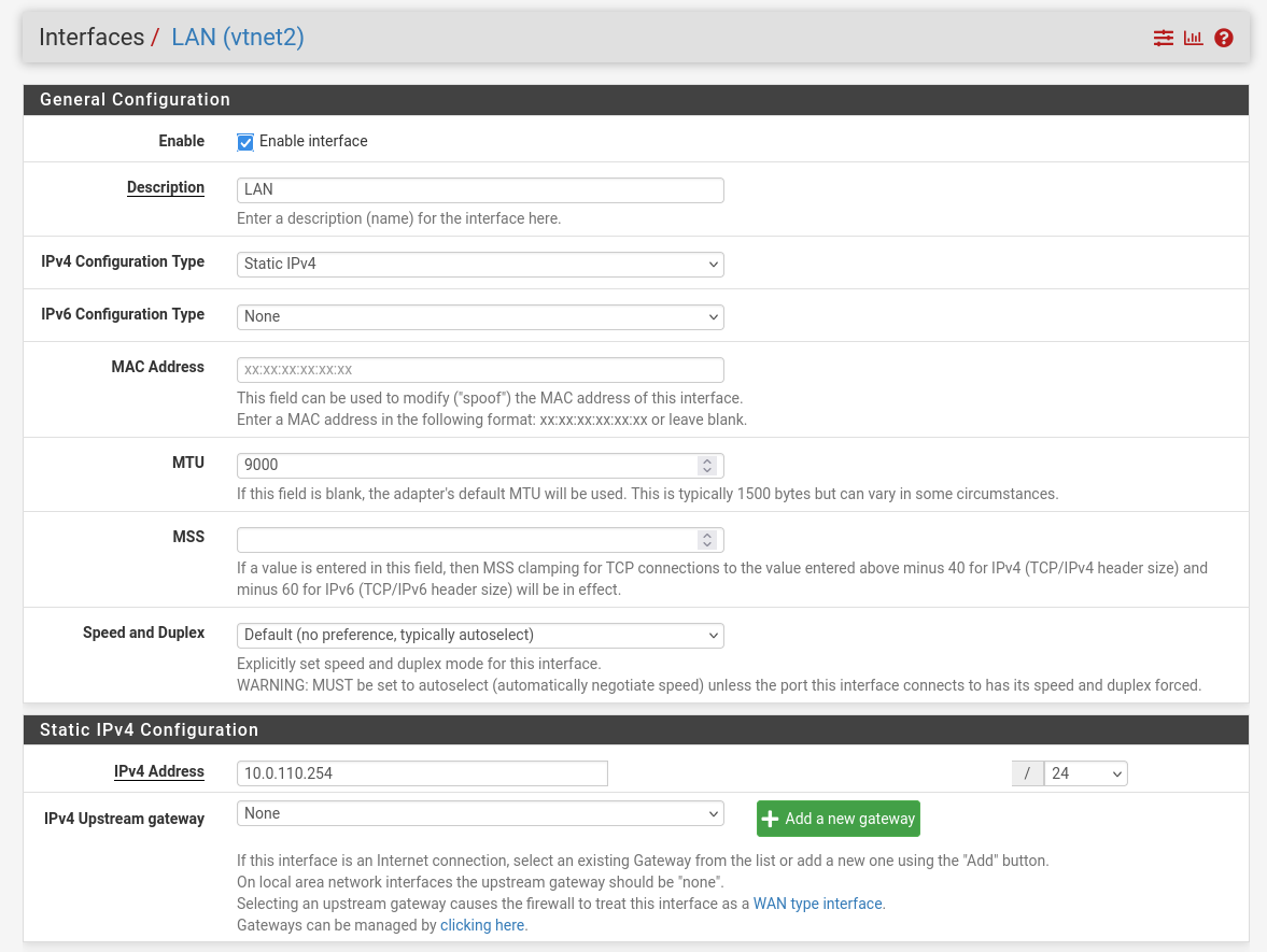
LAN – mark “Enable interface”, “IPv4 configuration type”: Static IPv4 ("IPv4 Address": 10.0.110.254/24, "IPv4 Upstream Gateway": None), “MTU”: 9000
-
OPT1 – mark “Enable interface”, “IPv4 configuration type”: Static IPv4 ("IPv4 Address": 172.169.50.1/30, "IPv4 Upstream Gateway": None), “MTU”: 9000
-
-
Firewall:
-
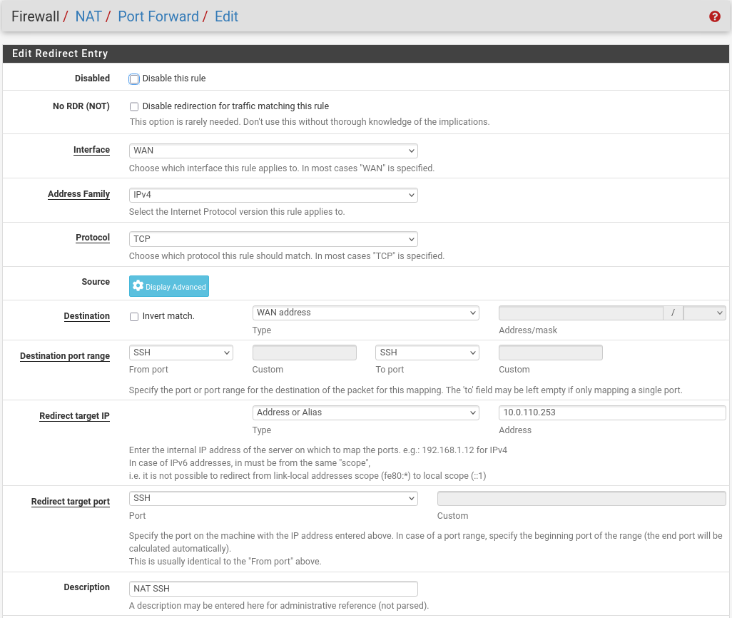
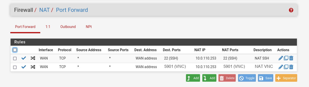
NAT -> Port Forward -> Add rule -> “Interface”: WAN, “Address Family”: IPv4, “Protocol”: TCP, “Destination”: WAN address, “Destination port range”: (“From port”: SSH, “To port”: SSH), “Redirect target IP”: (“Type”: Address or Alias, “Address”: 10.0.110.253), “Redirect target port”: SSH, “Description”: NAT SSH
-
NAT -> Port Forward -> Add rule -> “Interface”: WAN, “Address Family”: IPv4, “Protocol”: TCP, “Destination”: WAN address, “Destination port range”: (“From port”: 5901, “To port”: 5901), “Redirect target IP”: (“Type”: Address or Alias, “Address”: 10.0.110.253), “Redirect target port”: 5901, “Description”: NAT VNC
-
-
-
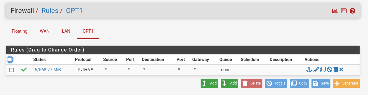
Rules -> OPT1 -> Add rule -> “Action”: Pass, “Interface”: OPT1, “Address Family”: IPv4+IPv6, “Protocol”: Any, “Source”: Any, “Destination”: Any
-
-
System:
-
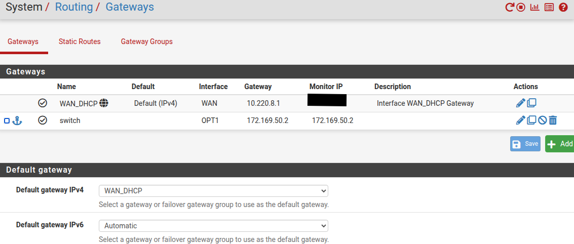
Routing → Gateways → Add → “Interface”: OPT1, “Address Family”: IPv4, “Name”: switch, “Gateway”: 172.169.50.2 → Click "Save"→ Under "Default Gateway" - "Default gateway IPv4" choose WAN_DHCP → Click "Save"
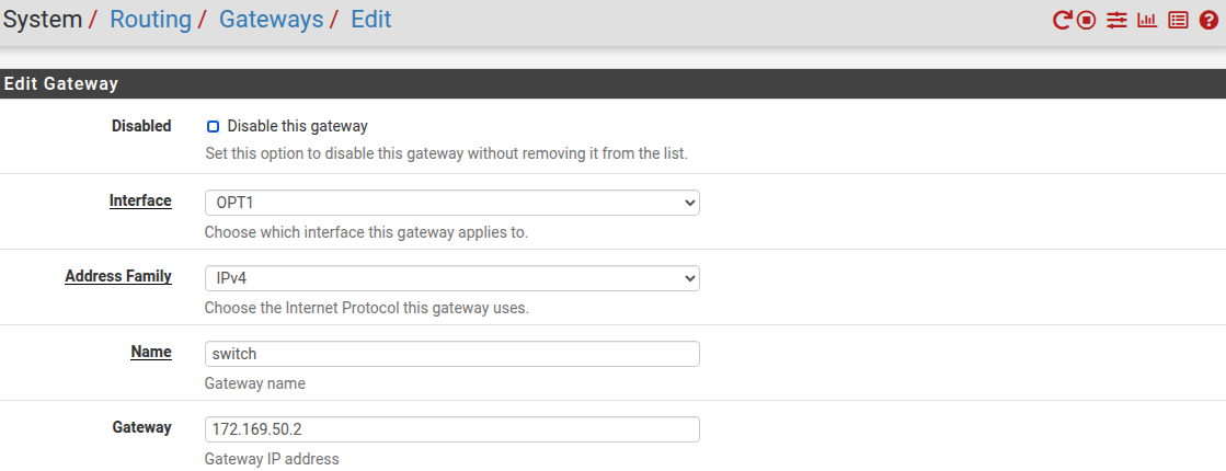
Note that the IP addresses from the Trusted LAN network under "Gateway" and "Monitor IP" are blurred.
-
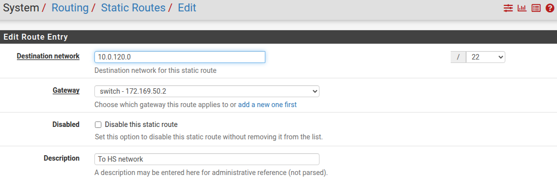
Routing → Static Routes → Add → “Destination network”: 10.0.120.0/22, “Gateway”: switch – 172.169.50.2, “Description”: To HS network → Click "Save"
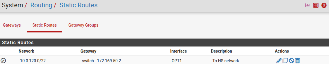
-
MaaS VM
Suggested specifications:
-
vCPU: 4
-
RAM: 4GB
-
Storage: 50GB
-
Network interface: Bridge device, connected to
mgmt-br
Procedure:
-
Perform a regular Ubuntu installation on the MaaS VM.
-
Create the following Netplan configuration to enable internet connectivity and DNS resolution:
Use
10.0.110.254as a temporary DNS nameserver. After the MaaS installation, replace this with the MaaS IP address (10.0.110.252) in both the Jump and MaaS VM Netplan files.
MaaS netplan
YAMLnetwork: ethernets: enp1s0: dhcp4: false addresses: [10.0.110.252/24] nameservers: search: [dpf.rdg.local.domain] addresses: [10.0.110.254] routes: - to: default via: 10.0.110.254 version: 2 -
Apply the netplan configuration:
MaaS Console
depuser@maas:~$ sudo netplan apply -
Update and upgrade the system:
MaaS Console
sudo apt update -y sudo apt upgrade -y -
Install PostgreSQL and configure the database for MaaS:
MaaS Console
$ sudo -i # apt install -y postgresql # systemctl enable --now postgresql # systemctl disable --now systemd-timesyncd # export MAAS_DBUSER=maasuser # export MAAS_DBPASS=maaspass # export MAAS_DBNAME=maas # sudo -i -u postgres psql -c "CREATE USER \"$MAAS_DBUSER\" WITH ENCRYPTED PASSWORD '$MAAS_DBPASS'" # sudo -i -u postgres createdb -O "$MAAS_DBUSER" "$MAAS_DBNAME" -
Install MaaS:
MaaS Console
snap install maas -
Initialize MaaS:
MaaS Console
maas init region+rack --maas-url http://10.0.110.252:5240/MAAS --database-uri "postgres://$MAAS_DBUSER:$MAAS_DBPASS@localhost/$MAAS_DBNAME" -
Create an admin account:
MaaS Console
maas createadmin --username admin --password admin --email admin@example.com -
Save the admin API key:
MaaS Console
maas apikey --username admin > admin-apikey -
Log in to the MaaS server:
MaaS Console
maas login admin http://localhost:5240/MAAS "$(cat admin-apikey)" -
Configure MaaS (Substitute <Trusted_LAN_NTP_IP> and <Trusted_LAN_DNS_IP> with the IP addresses in your environment):
MaaS Console
maas admin domain update maas name="dpf.rdg.local.domain" maas admin maas set-config name=ntp_servers value="<Trusted_LAN_NTP_IP>" maas admin maas set-config name=network_discovery value="disabled" maas admin maas set-config name=upstream_dns value="<Trusted_LAN_DNS_IP>" maas admin maas set-config name=dnssec_validation value="no" maas admin maas set-config name=default_osystem value="ubuntu" -
Define and configure IP ranges and subnets:
MaaS Console
maas admin ipranges create type=dynamic start_ip="10.0.110.51" end_ip="10.0.110.120" maas admin ipranges create type=reserved start_ip="10.0.110.10" end_ip="10.0.110.10" comment="c-plane VIP" maas admin ipranges create type=reserved start_ip="10.0.110.200" end_ip="10.0.110.200" comment="kamaji VIP" maas admin ipranges create type=reserved start_ip="10.0.110.251" end_ip="10.0.110.254" comment="dpfmgmt" maas admin vlan update 0 untagged dhcp_on=True primary_rack=maas mtu=9000 maas admin dnsresources create fqdn=kube-vip.dpf.rdg.local.domain ip_addresses=10.0.110.10 maas admin dnsresources create fqdn=jump.dpf.rdg.local.domain ip_addresses=10.0.110.253 maas admin dnsresources create fqdn=fw.dpf.rdg.local.domain ip_addresses=10.0.110.254 -
Configure static DHCP leases for the worker nodes (replace MAC address as appropriate with your workers MGMT interface MAC):
MaaS Console
maas admin reserved-ips create ip="10.0.110.21" mac_address="04:32:01:60:0d:da" comment="worker1" maas admin reserved-ips create ip="10.0.110.22" mac_address="04:32:01:5f:cb:e0" comment="worker2" -
Complete MaaS setup:
-
Connect to the Jump node GUI and access the MaaS UI at
http://10.0.110.252:5240/MAAS. -
On the first page, verify the "Region Name" and "DNS Forwarder," then continue.
-
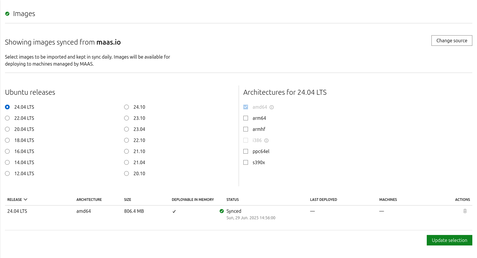
On the image selection page, verify that Ubuntu 24.04 LTS (amd64) image is synced and continue.
-
Import the previously generated SSH key (
id_rsa.pub) for thedepuserinto the MaaS admin user profile and finalize the setup.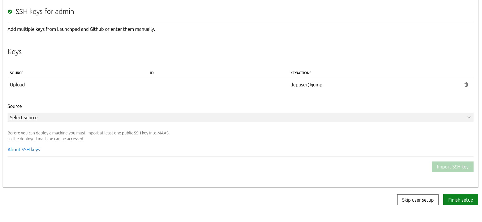
-
-
Update the DNS nameserver IP address in both Jump and MaaS VM Netplan files from
10.0.110.254to10.0.110.252and reapply the configuration.
K8s Master VMs
Suggested specifications:
-
vCPU: 8
-
RAM: 16GB
-
Storage: 100GB
-
Network interface: Bridge device, connected to
mgmt-br
-
Before provisioning the Kubernetes (K8s) Master VMs with MaaS, create the required virtual disks with empty storage. Use the following one-liner to create three 100 GB QCOW2 virtual disks:
Hypervisor Console
for i in $(seq 1 3); do qemu-img create -f qcow2 /var/lib/libvirt/images/master$i.qcow2 100G; doneThis command generates the following disks in the
/var/lib/libvirt/images/directory:-
master1.qcow2 -
master2.qcow2 -
master3.qcow2
-
-
Configure VMs in virt-manager:
-
Open virt-manager and create three virtual machines:
-
Assign the corresponding virtual disk (
master1.qcow2,master2.qcow2, ormaster3.qcow2) to each VM. -
Configure each VM with the suggested specifications (vCPU, RAM, storage, and network interface).
-
-
During the VM setup, ensure the NIC is selected under the Boot Options tab. This ensures the VMs can PXE boot for MaaS provisioning.
-
Once the configuration is complete, shut down all the VMs.
-
-
After the VMs are created and configured, proceed to provision them via the MaaS interface. MaaS will handle the OS installation and further setup as part of the deployment process.
Provision Master VMs and Worker Nodes Using MaaS
Master VMs
Install virsh and Set Up SSH Access
-
SSH to the MaaS VM from the Jump node:
MaaS Console
depuser@jump:~$ ssh maas depuser@maas:~$ sudo -i -
Install the
virshclient to communicate with the hypervisor:MaaS Console
# apt install -y libvirt-clients -
Generate an SSH key for the
rootuser and copy it to the hypervisor user in thelibvirtdgroup:MaaS Console
# ssh-keygen -t rsa # ssh-copy-id ubuntu@<hypervisor_MGMT_IP> -
Verify SSH access and
virshcommunication with the hypervisor:MaaS Console
# virsh -c qemu+ssh://ubuntu@<hypervisor_MGMT_IP>/system list --allExpected output:
MaaS Console
Id Name State ------------------------------ 1 fw running 2 jump running 3 maas running - master1 shut off - master2 shut off - master3 shut off -
Copy the SSH key to the required MaaS directory (for snap-based installations):
MaaS Console
# mkdir -p /var/snap/maas/current/root/.ssh
# cp .ssh/id_rsa* /var/snap/maas/current/root/.ssh/
Get MAC Addresses of the Master VMs
Retrieve the MAC addresses of the Master VMs:
MaaS Console
# for i in $(seq 1 3); do virsh -c qemu+ssh://ubuntu@<hypervisor_MGMT_IP>/system dumpxml master$i | grep 'mac address'; done
Example output:
MaaS Console
<mac address='52:54:00:a9:9c:ef'/>
<mac address='52:54:00:19:6b:4d'/>
<mac address='52:54:00:68:39:7f'/>
Add Master VMs to MaaS
-
Add the Master VMs to MaaS:
Once added, MaaS will automatically start the newly added VMs commissioning (discovery and introspection).
MaaS Console
# maas admin machines create hostname=master1 architecture=amd64/generic mac_addresses='52:54:00:a9:9c:ef' power_type=virsh power_parameters_power_address=qemu+ssh://ubuntu@<hypervisor_MGMT_IP>/system power_parameters_power_id=master1 skip_bmc_config=1 testing_scripts=none
Success.
Machine-readable output follows:
{
    "description": "",
    "status_name": "Commissioning",
...
    "status": 1,
...
    "system_id": "c3seyq",
...
    "fqdn": "master1.dpf.rdg.local.domain",
    "power_type": "virsh",
...
    "status_message": "Commissioning",
    "resource_uri": "/MAAS/api/2.0/machines/c3seyq/"
}

# maas admin machines create hostname=master2 architecture=amd64/generic mac_addresses='52:54:00:19:6b:4d' power_type=virsh power_parameters_power_address=qemu+ssh://ubuntu@<hypervisor_MGMT_IP>/system power_parameters_power_id=master2 skip_bmc_config=1 testing_scripts=none

# maas admin machines create hostname=master3 architecture=amd64/generic mac_addresses='52:54:00:68:39:7f' power_type=virsh power_parameters_power_address=qemu+ssh://ubuntu@<hypervisor_MGMT_IP>/system power_parameters_power_id=master3 skip_bmc_config=1 testing_scripts=none
Repeat the command formaster2andmaster3with their respective MAC addresses. -
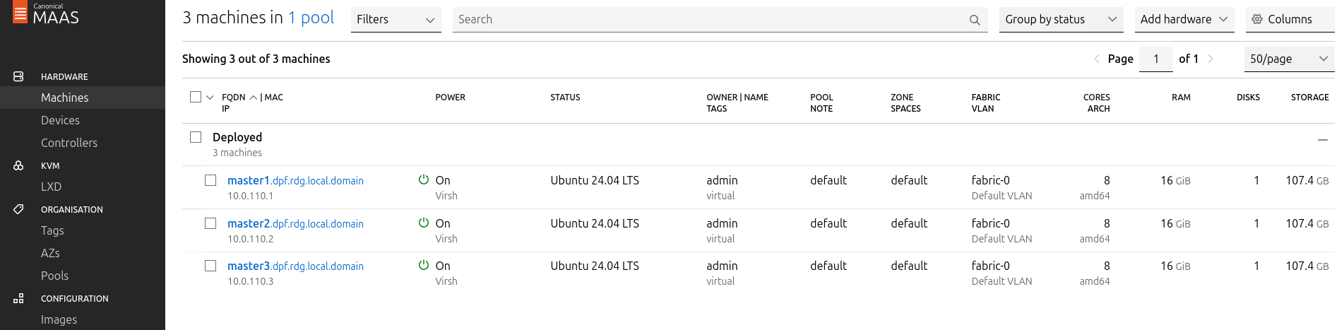
Verify commissioning by waiting for the status to change to "Ready" in MaaS.
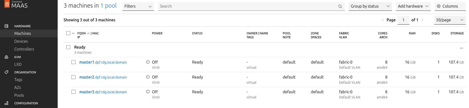
After commissioning, the next phase is the deployment (OS provisioning).
Configure OVS Bridges on Master VMs
To be able to have persistency across reboots, create an OVS-bridge from each management interface of the master nodes and assign it a static IP address.
For each Master VM:
-
Create an OVS bridge in the MaaS Network tab:
-
Navigate to Network → Management Interface → Create Bridge.
-
Configure as follows:
-
Name:
brenp1s0(prefixbradded to the interface name) -
Bridge Type: Open vSwitch (ovs)
-
Subnet: 10.0.110.0/24
-
IP Mode: Static (Client configured)
-
Address: Assign
10.0.110.1formaster1,10.0.110.2formaster2, and10.0.110.3formaster3.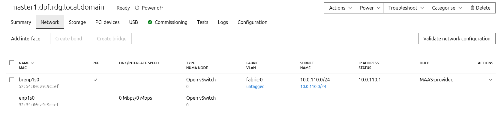
-
-
-
Save the interface settings for each VM.
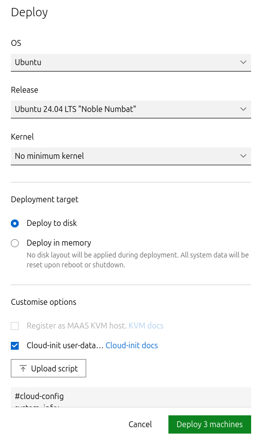
Deploy Master VMs Using Cloud-Init
-
Use the following cloud-init script to configure the necessary software and ensure OVS bridge persistency:
Replace
enp1s0andbrenp1s0in the following cloud-init with your interface names as displayed in MaaS network tab.
Master nodes cloud-init
YAML#cloud-config system_info: default_user: name: depuser passwd: "$6$jOKPZPHD9XbG72lJ$evCabLvy1GEZ5OR1Rrece3NhWpZ2CnS0E3fu5P1VcZgcRO37e4es9gmriyh14b8Jx8gmGwHAJxs3ZEjB0s0kn/" lock_passwd: false groups: [adm, audio, cdrom, dialout, dip, floppy, lxd, netdev, plugdev, sudo, video] sudo: ["ALL=(ALL) NOPASSWD:ALL"] shell: /bin/bash ssh_pwauth: True package_upgrade: true runcmd: - apt-get update - apt-get -y install openvswitch-switch nfs-common - | UPLINK_MAC=$(cat /sys/class/net/enp1s0/address) ovs-vsctl set Bridge brenp1s0 other-config:hwaddr=$UPLINK_MAC ovs-vsctl br-set-external-id brenp1s0 bridge-id brenp1s0 -- br-set-external-id brenp1s0 bridge-uplink enp1s0 -
Deploy the master VMs:
-
Select all three Master VMs → Actions → Deploy.
-
Toggle Cloud-init user-data and paste the cloud-init script.
-
Start the deployment and wait for the status to change to "Ubuntu 24.04 LTS".
-
Verify Deployment
-
SSH into the Master VMs from the Jump node:
Jump Node Console
depuser@jump:~$ ssh master1 depuser@master1:~$ -
Run
sudowithout password:Master1 Console
depuser@master1:~$ sudo -i
root@master1:~#
-
Verify installed packages:
Master1 Console
root@master1:~# apt list --installed | egrep 'openvswitch-switch|nfs-common' nfs-common/noble-updates,now 1:2.6.4-3ubuntu5.1 amd64 [installed] openvswitch-switch/noble-updates,now 3.3.4-0ubuntu0.24.04.1 amd64 [installed] -
Check OVS bridge attributes:
Master1 Console
root@master1:~# ovs-vsctl list bridge brenp1s0Output example:
Master1 Console
...
external_ids        : {bridge-id=brenp1s0, bridge-uplink=enp1s0, netplan="true", "netplan/global/set-fail-mode"=standalone, "netplan/mcast_snooping_enable"="false", "netplan/rstp_enable"="false"}
...
other_config        : {hwaddr="52:54:00:a9:9c:ef"}
...
-
Verify that
enp1s0andbrenp1s0are configured with 9000 MTU (replaceenp1s0andbrenp1s0with your interface names):Master1 Console
root@master1:~# ip a show enp1s0; ip a show brenp1s0
2: enp1s0: <BROADCAST,MULTICAST,UP,LOWER_UP> mtu 9000 qdisc pfifo_fast master ovs-system state UP group default qlen 1000
    link/ether 52:54:00:a9:9c:ef brd ff:ff:ff:ff:ff:ff
4: brenp1s0: <BROADCAST,MULTICAST,UP,LOWER_UP> mtu 9000 qdisc noqueue state UNKNOWN group default qlen 1000
    link/ether 52:54:00:a9:9c:ef brd ff:ff:ff:ff:ff:ff
    inet 10.0.110.1/24 brd 10.0.110.255 scope global brenp1s0
       valid_lft forever preferred_lft forever
    inet6 fe80::5054:ff:fea9:9cef/64 scope link
       valid_lft forever preferred_lft forever
Finalize Setup
Reboot the Master VMs to complete the provisioning.
Master1 Console
root@master1:~# reboot
Worker Nodes
Create Worker Machines in MaaS
-
Add the worker nodes to MaaS using
ipmias the power type. Replace placeholders with your specific IPMI credentials and IP addresses:MaaS Console
# maas admin machines create hostname=worker1 architecture=amd64 power_type=ipmi power_parameters_power_driver=LAN_2_0 power_parameters_power_user=<IPMI_username_worker1> power_parameters_power_pass=<IPMI_password_worker1> power_parameters_power_address=<IPMI_address_worker1> power_parameters_workaround_flags=opensesspriv power_parameters_workaround_flags=nochecksumcheckOutput example:
MaaS Console
... Success. Machine-readable output follows: { "description": "", "status_name": "Commissioning", ... "status": 1, ... "system_id": "pbskd3", ... "fqdn": "worker1.dpf.rdg.local.domain", ... "power_type": "ipmi", ... "resource_uri": "/MAAS/api/2.0/machines/pbskd3/" } -
Repeat the command for
worker2with its respective credentials:MaaS Console
# maas admin machines create hostname=worker2 architecture=amd64 power_type=ipmi power_parameters_power_driver=LAN_2_0 power_parameters_power_user=<IPMI_username_worker2> power_parameters_power_pass=<IPMI_password_worker2> power_parameters_power_address=<IPMI_address_worker2> power_parameters_workaround_flags=opensesspriv power_parameters_workaround_flags=nochecksumcheck
Once added, MaaS will automatically start commissioning the worker nodes (discovery and introspection).
Create a Tag for Kernel Parameters
Create an entity called "Tag" to configure kernel parameters for the worker nodes.
-
In the MaaS UI sidebar, go to Organization → Tags → Create New Tag and define
-
"Tag name":
compute_performance -
"Kernel options":
-
-
Substitute the values for
isolcpus,nohz_full, andrcu_nocbsto the CPU cores in the NUMA node which the BlueField-3 is connected to:If you are not sure in which NUMA node BlueField is connected to, select the worker node in the Machines tab, go to Network settings and check the value under TYPE NUMA NODE.
Kernel options for worker nodes
intel_iommu=on iommu=pt numa_balancing=disable processor.max_cstate=0 isolcpus=28-55,84-111 nohz_full=28-55,84-111 rcu_nocbs=28-55,84-111 -
Apply the tag:
-
Go to Machines → Select a worker node → Configuration → Edit Tag → Select
compute_performance→ Save. -
Repeat for the other worker node.
-
Adjust Network Settings
For each worker node, configure the network interfaces:
-
Management Adapter:
-
Go to Network → Select the host management adapter (e.g.,
ens15f0) → Create Bridge -
Name:
br-dpu -
Bridge Type: Standard
-
Subnet:
10.0.110.0/24 -
IP Mode: Dynamic
-
Save the interface
-
Repeat these steps for the second worker node.
Deploy Worker Nodes Using Cloud-Init
-
Use the following cloud-init script for deployment:
Worker node cloud-init
YAML#cloud-config system_info: default_user: name: depuser passwd: "$6$jOKPZPHD9XbG72lJ$evCabLvy1GEZ5OR1Rrece3NhWpZ2CnS0E3fu5P1VcZgcRO37e4es9gmriyh14b8Jx8gmGwHAJxs3ZEjB0s0kn/" lock_passwd: false groups: [adm, audio, cdrom, dialout, dip, floppy, lxd, netdev, plugdev, sudo, video] sudo: ["ALL=(ALL) NOPASSWD:ALL"] shell: /bin/bash ssh_pwauth: True package_upgrade: true runcmd: - apt-get update - apt-get -y install nfs-common -
Deploy the worker nodes by selecting the worker nodes in MaaS → Actions → Deploy → Customize options → Enable Cloud-init user-data → Paste the cloud-init script → Deploy.
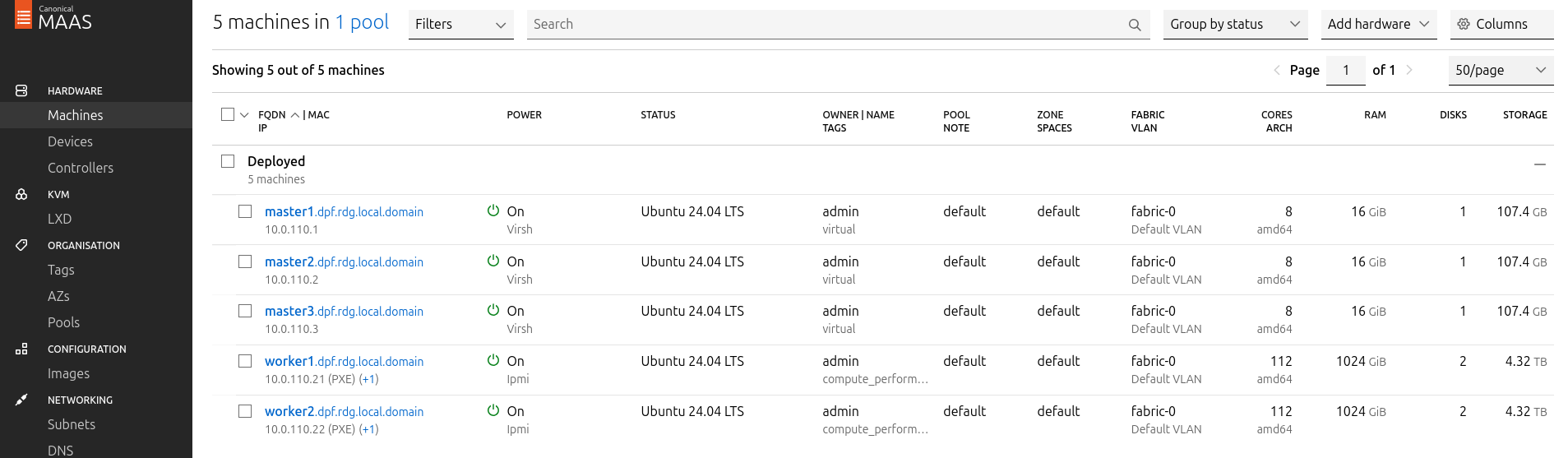
Verify Deployment
After the deployment is complete verify that the worker nodes have been deployed successfully with the following commands:
-
SSH without password from the jump node:
Jump Node Console
depuser@jump:~$ ssh worker1 depuser@worker1:~$ -
Run
sudowithout password:Worker1 Console
depuser@worker1:~$ sudo -i
root@worker1:~#
-
Validate that
nfs-commonpackage was installed:Worker1 Console
root@worker1:~# apt list --installed | grep 'nfs-common'
nfs-common/noble-updates,now 1:2.6.4-3ubuntu5.1 amd64 [installed]
-
/proc/cmdlineis configured with the correct parameters and that IOMMU is indeed inpassthroughmode:Worker1 Console
root@worker1:~# cat /proc/cmdline BOOT_IMAGE=/boot/vmlinuz-6.8.0-90-generic root=UUID=d2365b16-d371-4503-a583-a1768dd27e0c ro intel_iommu=on iommu=pt numa_balancing=disable processor.max_cstate=0 isolcpus=28-55,84-111 nohz_full=28-55,84-111 rcu_nocbs=28-55,84-111 root@worker1:~# dmesg | grep 'type: Passthrough' [ 5.033173] iommu: Default domain type: Passthrough (set via kernel command line) -
ens15f0andbr-dpuare with 9000 MTU (replaceens15f0with your interface name):Worker1 Console
root@worker1:~# ip a show ens15f0; ip a show br-dpu
2: ens15f0: <BROADCAST,MULTICAST,UP,LOWER_UP> mtu 9000 qdisc mq master br-dpu state UP group default qlen 1000
    link/ether 04:32:01:60:0d:da brd ff:ff:ff:ff:ff:ff
    altname enp53s0f0
8: br-dpu: <BROADCAST,MULTICAST,UP,LOWER_UP> mtu 9000 qdisc noqueue state UP group default qlen 1000
    link/ether 04:32:01:60:0d:da brd ff:ff:ff:ff:ff:ff
    inet 10.0.110.21/24 metric 100 brd 10.0.110.255 scope global dynamic br-dpu
       valid_lft 403sec preferred_lft 403sec
    inet6 fe80::632:1ff:fe60:dda/64 scope link
       valid_lft forever preferred_lft forever
Finalize Deployment
Reboot the worker nodes:
Jump Node Console
root@worker1:~# reboot
The infrastructure is now ready for the K8s deployment.
K8s Cluster Deployment and Configuration
Kubespray Deployment and Configuration
In this solution, the Kubernetes (K8s) cluster is deployed using a modified Kubespray (based on release v2.28.1) with a non-root depuser account from the Jump Node. The modifications in Kubespray are designed to meet the DPF prerequisites as described in the User Manual and facilitate cluster deployment and scaling.
-
Download the modified Kubespray archive: modified_kubespray_v2.31.0.tar.gz .
-
Extract the contents and navigate to the extracted directory:
Jump Node Console
$ tar -xzf /home/depuser/modified_kubespray_v2.31.1.tar.gz $ cd kubespray/ depuser@jump:~/kubespray$ -
Set the K8s API VIP address and DNS record. Replace it with your own IP address and DNS record if different:
Jump Node Console
depuser@jump:~/kubespray$ sed -i '/# kube_vip_address:/s/.*/kube_vip_address: 10.0.110.10/' inventory/mycluster/group_vars/k8s_cluster/addons.yml depuser@jump:~/kubespray$ sed -i '/apiserver_loadbalancer_domain_name:/s/.*/apiserver_loadbalancer_domain_name: "kube-vip.dpf.rdg.local.domain"/' roles/kubespray_defaults/defaults/main/main.yml -
Install the necessary dependencies and set up the Python virtual environment:
Jump Node Console
depuser@jump:~/kubespray$ sudo apt -y install python3-pip jq python3.12-venv depuser@jump:~/kubespray$ python3 -m venv .venv depuser@jump:~/kubespray$ source .venv/bin/activate (.venv) depuser@jump:~/kubespray$ python3 -m pip install --upgrade pip (.venv) depuser@jump:~/kubespray$ pip install -U -r requirements.txt -
Review and edit the
inventory/mycluster/hosts.yamlfile to define the cluster nodes. The following is the configuration for this deployment:-
All of the nodes are already labeled and annotated as per DPF user manual prerequisites.
-
The worker nodes include additional kubelet configuration which will be applied during their deployment to achieve best performance, allowing:
-
Containers in Guaranteed pods with integer CPU requests access to exclusive CPUs on the node.
-
Reserve some cores for the system using the
reservedSystemCPUsoption (kubelet requires a CPU reservation greater than zero to be made when the static policy is enabled), and make sure they belong to NUMA 0 (because the NIC in the example is wired to NUMA node 1, use cores from NUMA 1 if the NIC is wired to NUMA node 0). -
Define the topology to be
single-numa-nodeso it only allows a pod to be admitted if all requested CPUs and devices can be allocated from exactly one NUMA node.
-
-
The
kube_nodehostsworker1andworker2are marked with # to only deploy the cluster with control plane nodes at the beginning (worker nodes will be added later on after the various components that are necessary for the DPF system are installed).
-
Deploying Cluster Using Kubespray Ansible Playbook
-
Run the following command from the Jump Node to initiate the deployment process:
Ensure you are in the Python virtual environment (
.venv) when running the command.Jump Node Console
(.venv) depuser@jump:~/kubespray$ ansible-playbook -i inventory/mycluster/hosts.yaml --become --become-user=root cluster.yml -
It takes a while for this deployment to complete. Make sure there are no errors. Successful result example:
Jump Node ConsolePLAY RECAP ********************************************************************* master1 : ok=525 changed=117 unreachable=0 failed=0 skipped=740 rescued=0 ignored=1 master2 : ok=483 changed=111 unreachable=0 failed=0 skipped=668 rescued=0 ignored=1 master3 : ok=485 changed=112 unreachable=0 failed=0 skipped=666 rescued=0 ignored=1It is recommended to keep the shell from which Kubespray has been running open, later on it will be useful when performing cluster scale out to add the worker nodes.
K8s Deployment Verification
To simplify managing the K8s cluster from the Jump Host, set up kubectl with bash auto-completion.
-
Copy
kubectland the kubeconfig file frommaster1to the Jump Host:Jump Node Console
## Connect to master1 depuser@jump:~$ ssh master1 depuser@master1:~$ cp /usr/local/bin/kubectl /tmp/ depuser@master1:~$ sudo cp /root/.kube/config /tmp/kube-config depuser@master1:~$ sudo chmod 644 /tmp/kube-config -
In another terminal tab, copy the files to the Jump Host:
Jump Node Console
depuser@jump:~$ scp master1:/tmp/kubectl /tmp/ depuser@jump:~$ sudo chown root:root /tmp/kubectl depuser@jump:~$ sudo mv /tmp/kubectl /usr/local/bin/ depuser@jump:~$ mkdir -p ~/.kube depuser@jump:~$ scp master1:/tmp/kube-config ~/.kube/config depuser@jump:~$ chmod 600 ~/.kube/config -
Enable bash auto-completion for
kubectl:-
Verify if bash-completion is installed:
Jump Node Console
depuser@jump:~$ type _init_completionIf installed, the output will include:
Jump Node Console
_init_completion is a function -
If not installed, install it:
Jump Node Console
depuser@jump:~$ sudo apt install -y bash-completion -
Set up the
kubectlcompletion script:Jump Node Console
depuser@jump:~$ kubectl completion bash | sudo tee /etc/bash_completion.d/kubectl > /dev/null
depuser@jump:~$ bash
-
-
Check the status of the nodes in the cluster:
Jump Node Console
depuser@jump:~$ kubectl get nodes
Expected output:Nodes will be in the
NotReadystate because the deployment did not include CNI components.Jump Node Console
NAME STATUS ROLES AGE VERSION master1 NotReady control-plane 12m v1.35.4 master2 NotReady control-plane 12m v1.35.4 master3 NotReady control-plane 12m v1.35.4 -
Check the pods in all namespaces:
Jump Node Console
depuser@jump:~$ kubectl get pods -A
Expected output:corednsanddns-autoscalerpods will be in thePendingstate due to the absence of CNI components.Jump Node Console
NAMESPACE     NAME                              READY   STATUS    RESTARTS   AGE
kube-system   coredns-5c54f84c97-7fl6m          0/1     Pending   0          12m
kube-system   dns-autoscaler-56cb45595c-mkdjq   0/1     Pending   0          12m
kube-system   kube-apiserver-master1            1/1     Running   0          13m
kube-system   kube-apiserver-master2            1/1     Running   0          12m
kube-system   kube-apiserver-master3            1/1     Running   0          12m
kube-system   kube-controller-manager-master1   1/1     Running   1          13m
kube-system   kube-controller-manager-master2   1/1     Running   1          12m
kube-system   kube-controller-manager-master3   1/1     Running   1          12m
kube-system   kube-scheduler-master1            1/1     Running   1          13m
kube-system   kube-scheduler-master2            1/1     Running   1          12m
kube-system   kube-scheduler-master3            1/1     Running   1          12m
kube-system   kube-vip-master1                  1/1     Running   0          13m
kube-system   kube-vip-master2                  1/1     Running   0          12m
kube-system   kube-vip-master3                  1/1     Running   0          12m
DPF Installation
Software Prerequisites and Required Variables
-
Start by installing the remaining software perquisites.
Jump Node Console
## Verify that envsubst utility is installed depuser@jump:~$ which envsubst /usr/bin/envsubst ## Verify that the Go toolchain is installed (required by `make test-deploy-helmfile` to build the helm-diff plugin from source) depuser@jump:~$ which go && go version /usr/bin/go go version go1.22.2 linux/amd64 ## If not installed, apt-install (Ubuntu 24.04): depuser@jump:~$ sudo apt update && sudo apt install -y golang-1.22 -
Proceed to clone the doca-platform Git repository:
Jump Node Console
git clone https://github.com/NVIDIA/doca-platform.git -
Change directory to doca-platform and checkout to tag v26.4.0:
Jump Node Console
cd doca-platform/ git checkout v26.4.0 -
Bootstrap the DPF-pinned helm + helmfile tooling:
Jump Node Console$ make helm helmfile helm-diff helm-git $ export PATH=$PWD/hack/tools/bin:$PATH $ which helm; helm version --short /home/depuser/doca-platform/hack/tools/bin/helm v3.18.3+g6838ebc -
Change directory to readme.md from where all the commands will be run:
Jump Node Console
cd docs/public/user-guides/host-trusted/use-cases/hbn-ovnk/ -
Use the following file to define the required variables for the installation:
Replace the values for the variables in the following file with the values that fit your setup. Specifically, pay attention to
DPU_P0,DPU_P0_VF1andDPUCLUSTER_INTERFACE.manifests/00-env-vars/envvars.env
Bash## IP Address for the Kubernetes API server of the target cluster on which DPF is installed. ## This should never include a scheme or a port. ## e.g. 10.10.10.10 export TARGETCLUSTER_API_SERVER_HOST=10.0.110.10 ## Port for the Kubernetes API server of the target cluster on which DPF is installed. export TARGETCLUSTER_API_SERVER_PORT=6443 ## IP address range for hosts in the target cluster on which DPF is installed. ## This is a CIDR in the form e.g. 10.10.10.0/24 export TARGETCLUSTER_NODE_CIDR=10.0.110.0/24 ## Virtual IP used by the load balancer for the DPU Cluster. Must be a reserved IP from the management subnet and not allocated by DHCP. export DPUCLUSTER_VIP=10.0.110.200 ## Interface on which the DPUCluster load balancer will listen. Should be the management interface of the control plane node. export DPUCLUSTER_INTERFACE=brenp1s0 ## The repository URL for the NVIDIA Helm chart registry. ## Usually this is the NVIDIA Helm NGC registry. For development purposes, this can be set to a different repository. export HELM_REGISTRY_REPO_URL=https://helm.ngc.nvidia.com/nvidia/doca ## The repository URL for the HBN container image. ## Usually this is the NVIDIA NGC registry. For development purposes, this can be set to a different repository. export HBN_NGC_IMAGE_URL=nvcr.io/nvidia/doca/doca_hbn ## The repository URL for the OVN-Kubernetes Helm chart. ## Usually this is the NVIDIA GHCR repository. For development purposes, this can be set to a different repository. export OVN_KUBERNETES_REPO_URL=oci://ghcr.io/mellanox/charts # OVN-Kubernetes chart tag export OVN_KUBERNETES_CHART_TAG=v26.4.0 ## POD_CIDR is the CIDR used for pods in the target Kubernetes cluster. export POD_CIDR=10.233.64.0/18 ## SERVICE_CIDR is the CIDR used for services in the target Kubernetes cluster. ## This is a CIDR in the form e.g. 10.10.10.0/24 export SERVICE_CIDR=10.233.0.0/18 ## The DPF REGISTRY is the Helm repository URL where the DPF Operator Chart resides. ## Usually this is the NVIDIA Helm NGC registry. For development purposes, this can be set to a different repository. export REGISTRY=https://helm.ngc.nvidia.com/nvidia/doca ## The DPF TAG is the version of the DPF components which will be deployed in this guide. export TAG=v26.4.0 ## URL to the BFB used in the `bfb.yaml` and linked by the DPUSet. export BFB_URL="https://content.mellanox.com/BlueField/BFBs/Ubuntu24.04/bf-bundle-3.4.0-92_26.04_ubuntu-24.04_64k_prod.bfb" -
Export environment variables for the installation:
Jump Node Console
source manifests/00-env-vars/envvars.env
CNI Installation
OVN Kubernetes is used as the primary CNI for the cluster. On worker nodes, the primary CNI will be accelerated by offloading work to the DPU. On control plane nodes, OVN Kubernetes will run without offloading.
-
Create the NS for the CNI:
Jump Node Console
kubectl create ns ovn-kubernetes -
Install the OVN Kubernetes CNI components from the helm chart substituting the environment variables with the ones we defined before.
Note that MTU field with value of
8940has been added to the yaml to override the default value and to be able to achieve better performance results. -
Run the following command:
Jump Node Console
envsubst < manifests/01-cni-installation/helm-values/ovn-kubernetes.yml | helm upgrade --install -n ovn-kubernetes ovn-kubernetes ${OVN_KUBERNETES_REPO_URL}/ovn-kubernetes-chart --version ${OVN_KUBERNETES_CHART_TAG} --values - -
Verify the CNI installation:
The following verification commands may need to be run multiple times to ensure the condition is met.
Jump Node Console
$ kubectl wait --for=condition=ready --namespace ovn-kubernetes pods --all --timeout=300s
pod/ovn-kubernetes-cluster-manager-8684b6bd7-mzm2r condition met
pod/ovn-kubernetes-identity-2r8tx condition met
pod/ovn-kubernetes-identity-7dxx9 condition met
pod/ovn-kubernetes-identity-vprfs condition met
pod/ovn-kubernetes-node-ltt2k condition met
pod/ovn-kubernetes-node-m49wl condition met
pod/ovn-kubernetes-node-stpgz condition met

$ kubectl wait --for=condition=ready nodes --all
node/master1 condition met
node/master2 condition met
node/master3 condition met

$ kubectl wait --for=condition=ready --namespace kube-system pods --all
pod/coredns-58cc5d8ddf-8q9ls condition met
pod/coredns-58cc5d8ddf-dtlkw condition met
pod/dns-autoscaler-5654b864c-jk8v7 condition met
pod/kube-apiserver-master1 condition met
pod/kube-apiserver-master2 condition met
pod/kube-apiserver-master3 condition met
pod/kube-controller-manager-master1 condition met
pod/kube-controller-manager-master2 condition met
pod/kube-controller-manager-master3 condition met
pod/kube-scheduler-master1 condition met
pod/kube-scheduler-master2 condition met
pod/kube-scheduler-master3 condition met
pod/kube-vip-master1 condition met
pod/kube-vip-master2 condition met
pod/kube-vip-master3 condition met
DPF Operator Installation
Additional Dependencies
-
The DPF Operator requires several prerequisite components to function properly in a Kubernetes environment. Starting with DPF v25.7, all Helm dependencies have been removed from the DPF chart. This means that all dependencies must be installed manually before installing the DPF chart itself. The following commands describe an opiniated approach to install those dependencies (for more information, check: Helm Prerequisites - NVIDIA Docs).
CNI must be installed and all nodes must beReadybefore running this command. Thenode-feature-discoveryDaemonSet deployed by this step requires nodes inReadystate to schedule its pods. Since OVN-Kubernetes is the cluster CNI, nodes remainNotReadyuntil the CNI Installation step above is complete. Running this command before the CNI step will cause acontext deadline exceededtimeout. Verify nodes are ready first:
Jump Node Console$ kubectl wait --for=condition=ready nodes --all --timeout=60s node/master1 condition met node/master2 condition met node/master3 condition met
-
From within the doca-platform directory (where you ran
make helm helmfile helm-diff helm-gitearlier in Software Prerequisites), install Helm dependencies:
Jump Node Console$ cd ~/doca-platform && make HELMFILE_FILE=deploy/helmfiles/prereqs.yaml test-deploy-helmfile Adding repo argoproj https://argoproj.github.io/argo-helm Adding repo node-feature-discovery https://kubernetes-sigs.github.io/node-feature-discovery/charts Adding repo clastix https://clastix.github.io/charts Adding repo jetstack https://charts.jetstack.io Adding repo local-storage git+https://github.com/rancher/local-path-provisioner@deploy/chart?ref=v0.0.34 UPDATED RELEASES: NAME NAMESPACE CHART VERSION DURATION local-path-provisioner local-path-provisioner local-storage/local-path-provisioner 0.0.34 20s cert-manager cert-manager jetstack/cert-manager v1.19.3 22s node-feature-discovery dpf-operator-system node-feature-discovery/node-feature-discovery 0.18.3 29s argo-cd dpf-operator-system argoproj/argo-cd 9.4.1 59s maintenance-operator dpf-operator-system oci://ghcr.io/mellanox/maintenance-operator-chart 0.3.0 24s kamaji dpf-operator-system oci://ghcr.io/nvidia/charts/kamaji 1.2.0 2m12s $ helm list -A NAME NAMESPACE REVISION STATUS CHART APP VERSION argo-cd dpf-operator-system 1 deployed argo-cd-9.4.1 v3.3.0 cert-manager cert-manager 1 deployed cert-manager-v1.19.3 v1.19.3 kamaji dpf-operator-system 1 deployed kamaji-1.2.0 v1.34.0-25.9.3 local-path-provisioner local-path-provisioner 1 deployed local-path-provisioner-0.0.34 v0.0.34 maintenance-operator dpf-operator-system 1 deployed maintenance-operator-chart-0.3.0 v0.3.0 node-feature-discovery dpf-operator-system 1 deployed node-feature-discovery-0.18.3 v0.18.3 ovn-kubernetes ovn-kubernetes 1 deployed ovn-kubernetes-chart-v26.4.0 v26.4.0 -
Ensure that the
KUBERNETES_SERVICE_HOSTandKUBERNETES_SERVICE_PORTenvironment variables are set in the node-feature-discovery-worker DaemonSet:
Jump Node Consolekubectl -n dpf-operator-system set env daemonset/node-feature-discovery-worker \ KUBERNETES_SERVICE_HOST=$TARGETCLUSTER_API_SERVER_HOST \ KUBERNETES_SERVICE_PORT=$TARGETCLUSTER_API_SERVER_PORT -
Verify the env override took effect:
Jump Node Console$ kubectl -n dpf-operator-system get ds node-feature-discovery-worker \ -o jsonpath='{.spec.template.spec.containers[*].env}' | jq . [ {"name": "NODE_NAME", "valueFrom": {"fieldRef": {"fieldPath": "spec.nodeName"}}}, {"name": "POD_NAME", "valueFrom": {"fieldRef": {"fieldPath": "metadata.name"}}}, {"name": "POD_UID", "valueFrom": {"fieldRef": {"fieldPath": "metadata.uid"}}}, {"name": "KUBERNETES_SERVICE_HOST", "value": "10.0.110.10"}, {"name": "KUBERNETES_SERVICE_PORT", "value": "6443"} ]
-
DPF Operator Deployment
-
Run the following commands to install the DPF Operator:
Jump Node Console
helm repo add --force-update dpf-repository ${REGISTRY} helm repo update helm upgrade --install -n dpf-operator-system dpf-operator dpf-repository/dpf-operator --version=$TAG -
Verify the DPF Operator installation by ensuring the deployment is available and all the pods are ready:
The following verification commands may need to be run multiple times to ensure the conditions are met.
Jump Node Console
$ kubectl rollout status deployment --namespace dpf-operator-system dpf-operator-controller-manager
deployment "dpf-operator-controller-manager" successfully rolled out

$ kubectl wait --for=condition=ready --namespace dpf-operator-system pods --all
pod/argo-cd-argocd-application-controller-0 condition met
pod/argo-cd-argocd-redis-6484cb5745-pjzzc condition met
pod/argo-cd-argocd-repo-server-5b7d948d5f-9vbrx condition met
pod/argo-cd-argocd-server-5cb97d876c-jzrrq condition met
pod/dpf-operator-controller-manager-5d5484fdb6-s4tkn condition met
pod/kamaji-6969fd5bfc-4x5lp condition met
pod/kamaji-etcd-0 condition met
pod/kamaji-etcd-1 condition met
pod/kamaji-etcd-2 condition met
pod/maintenance-operator-68c794b549-qlbl4 condition met
pod/node-feature-discovery-gc-6f8b8b68d6-ctqk4 condition met
pod/node-feature-discovery-master-6df5b98bcf-krb7d condition met
DPF System Installation
This section involves creating the DPF system components and some basic infrastructure required for a functioning DPF-enabled cluster.
-
The following YAML files define the DPFOperatorConfig to install the DPF System components and the DPUCluster to serve as Kubernetes control plane for DPU nodes.
Note that to achieve high performance results you need to adjust the
operatorconfig.yamlto support MTU 9000. -
Create NS for the Kubernetes control plane of the DPU nodes:
Jump Node Console
kubectl create ns dpu-cplane-tenant1 -
Apply the previous YAML files:
Jump Node Console
cat manifests/03-dpf-system-installation/*.yaml | envsubst | kubectl apply -f - -
Verify the DPF system by ensuring that the provisioning and DPUService controller manager deployments are available, that all other deployments in the DPF Operator system are available, and that the DPUCluster is ready for nodes to join.
Jump Node Console
$ kubectl rollout status deployment --namespace dpf-operator-system dpf-provisioning-controller-manager dpuservice-controller-manager
deployment "dpf-provisioning-controller-manager" successfully rolled out
deployment "dpuservice-controller-manager" successfully rolled out

$ kubectl rollout status deployment --namespace dpf-operator-system
deployment "argo-cd-argocd-applicationset-controller" successfully rolled out
deployment "argo-cd-argocd-redis" successfully rolled out
deployment "argo-cd-argocd-repo-server" successfully rolled out
deployment "argo-cd-argocd-server" successfully rolled out
deployment "dpf-nodesriovdeviceplugin-controller" successfully rolled out
deployment "dpf-operator-controller-manager" successfully rolled out
deployment "dpf-provisioning-controller-manager" successfully rolled out
deployment "dpuservice-controller-manager" successfully rolled out
deployment "kamaji" successfully rolled out
deployment "kamaji-cm-controller-manager" successfully rolled out
deployment "maintenance-operator" successfully rolled out
deployment "node-feature-discovery-gc" successfully rolled out
deployment "node-feature-discovery-master" successfully rolled out

$ kubectl wait --for=condition=ready --namespace dpu-cplane-tenant1 dpucluster --all
dpucluster.provisioning.dpu.nvidia.com/dpu-cplane-tenant1 condition met
Install Components to Enable Accelerated CNI Nodes
OVN Kubernetes accelerates traffic by attaching a VF to each pod using the primary CNI. This VF is used to offload flows to the DPU. This section details the components needed to connect pods to the offloaded OVN Kubernetes CNI.
Install Multus and SRIOV Network Operator using NVIDIA Network Operator
-
Add the NVIDIA Network Operator Helm repository:
Jump Node Console
helm repo add nvidia https://helm.ngc.nvidia.com/nvidia --force-update -
The following
network-operator.yamlvalues file will be applied:
Deploy the operator:Jump Node Console
helm upgrade --no-hooks --install --create-namespace --namespace nvidia-network-operator network-operator nvidia/network-operator --version 26.1.0 -f ./manifests/04-enable-accelerated-cni/helm-values/network-operator.yml -
Ensure all the pods in nvidia-network-operator namespace are ready:
Jump Node Console
$ kubectl wait --for=condition=ready --namespace nvidia-network-operator pods --all
pod/network-operator-5c5dcf8689-kp4f7 condition met
Install OVN Kubernetes resource injection webhook
The OVN Kubernetes resource injection webhook is injected into each pod scheduled to a worker node with a request for a VF and a Network Attachment Definition. This webhook is part of the same helm chart as the other components of the OVN Kubernetes CNI. Here it is installed by adjusting the existing helm installation to add the webhook component to the installation.
-
The following
ovn-kubernetes.yamlvalues file will be applied:YAMLovn-kubernetes-resource-injector: ## Enable the ovn-kubernetes-resource-injector enabled: true -
Run the following command:
Jump Node Console
envsubst < manifests/04-enable-accelerated-cni/helm-values/ovn-kubernetes.yml | helm upgrade --install -n ovn-kubernetes ovn-kubernetes-resource-injector ${OVN_KUBERNETES_REPO_URL}/ovn-kubernetes-chart --version $OVN_KUBERNETES_CHART_TAG --values - -
Verify that the resource injector deployment has been successfully rolled out.
Jump Node Console
$ kubectl rollout status deployment --namespace ovn-kubernetes ovn-kubernetes-resource-injector
deployment "ovn-kubernetes-resource-injector" successfully rolled out
Apply NicClusterPolicy and SriovNetworkNodePolicy
-
The following NicClusterPolicy and SriovNetworkNodePolicy configuration files should be applied.
Apply those configuration files:Jump Node Console
cat manifests/04-enable-accelerated-cni/*.yaml | envsubst | kubectl apply -f - -
Verify the DPF system by ensuring that the following DaemonSets were successfully rolled out:
Jump Node Console
$ kubectl rollout status daemonset --namespace nvidia-network-operator kube-multus-ds
daemon set "kube-multus-ds" successfully rolled out
DPU Provisioning and Service Installation
-
Before deploying the objects under
manifests/05-dpudeployment-installationdirectory, few adjustments need to be made to later achieve better performance results.-
Create a new DPUFlavor using the following YAML:
The parameter
NUM_VF_MSIXis configured to be 48 in the provided example, which is suited for the HP servers that were used in this RDG.
Set it to the physical number of cores in the NUMA node the NIC is located in. -
Adjust
dpudeployment.yamlto reference the DPUFlavor suited for performance (This component provisions DPUs on the worker nodes and describes a set of DPUServices and DPUServiceChain that run on those DPUs): -
Set the
mtuto8940for the OVN DPUServiceConfig (to deploy the OVN Kubernetes workloads on the DPU with the same MTU as in the host): -
The rest of the configuration files remain the same, including:
-
HBN DPUServiceConfig to deploy HBN workloads to the DPUs.
-
BFB to download BlueField Bitstream to a shared volume.
YAML--- apiVersion: provisioning.dpu.nvidia.com/v1alpha1 kind: BFB metadata: name: bf-bundle-$TAG namespace: dpf-operator-system spec: url: $BFB_URL -
OVN DPUServiceTemplate to deploy OVN Kubernetes workloads to the DPUs.
-
HBN DPUServiceTemplate to deploy HBN workloads to the DPUs.
-
DOCA Telemetry Service (DTS) DPUServiceConfig and DPUServiceTemplate to deploy DTS to the DPUs.
YAML--- apiVersion: svc.dpu.nvidia.com/v1alpha1 kind: DPUServiceConfiguration metadata: name: dts namespace: dpf-operator-system spec: deploymentServiceName: "dts"YAML--- apiVersion: svc.dpu.nvidia.com/v1alpha1 kind: DPUServiceTemplate metadata: name: dts namespace: dpf-operator-system spec: deploymentServiceName: "dts" helmChart: source: repoURL: $HELM_REGISTRY_REPO_URL version: 1.25.5 chart: doca-telemetry -
Blueman DPUServiceConfig and DPUServiceTemplate to deploy Blueman to the DPUs.
YAML--- apiVersion: svc.dpu.nvidia.com/v1alpha1 kind: DPUServiceConfiguration metadata: name: blueman namespace: dpf-operator-system spec: deploymentServiceName: "blueman"YAML--- apiVersion: svc.dpu.nvidia.com/v1alpha1 kind: DPUServiceTemplate metadata: name: blueman namespace: dpf-operator-system spec: deploymentServiceName: "blueman" helmChart: source: repoURL: $HELM_REGISTRY_REPO_URL version: 1.0.8 chart: doca-blueman -
OVN DPUServiceCredentialRequest to allow cross cluster communication.
-
DPUServiceInterfaces for physical ports on the DPU.
-
OVN DPUServiceInterface to define the ports attached to OVN workloads on the DPU.
-
DPUServiceIPAM to set up IP Address Management on the DPUCluster.
-
DPUServiceIPAM for the loopback interface in HBN.
-
-
-
Apply all of the YAML files mentioned above using the following command:
Jump Node Console
cat manifests/05-dpudeployment-installation/*.yaml | envsubst | kubectl apply -f - bfb.provisioning.dpu.nvidia.com/bf-bundle-v26.4.0 created dpudeployment.svc.dpu.nvidia.com/ovn-hbn created dpuflavor.provisioning.dpu.nvidia.com/hbn-ovnk-v26.4.0-performance created dpuserviceconfiguration.svc.dpu.nvidia.com/blueman created dpuserviceconfiguration.svc.dpu.nvidia.com/dts created dpuserviceconfiguration.svc.dpu.nvidia.com/hbn created dpuserviceconfiguration.svc.dpu.nvidia.com/ovn created dpuservicetemplate.svc.dpu.nvidia.com/blueman created dpuservicetemplate.svc.dpu.nvidia.com/dts created dpuservicetemplate.svc.dpu.nvidia.com/hbn created dpuservicetemplate.svc.dpu.nvidia.com/ovn created dpuserviceipam.svc.dpu.nvidia.com/loopback created dpuserviceipam.svc.dpu.nvidia.com/pool1 created dpuservicecredentialrequest.svc.dpu.nvidia.com/ovn-dpu created dpuserviceinterface.svc.dpu.nvidia.com/ovn created dpuserviceinterface.svc.dpu.nvidia.com/p0 created dpuserviceinterface.svc.dpu.nvidia.com/p1 created -
Verify the DPU and Service installation by ensuring the DPUServices are created and have been reconciled, that the DPUServiceIPAMs have been reconciled, that the DPUServiceInterfaces have been reconciled, and that the DPUServiceChain have been reconciled:
These verification commands may need to be run multiple times to ensure the conditions are met.
Jump Node Console
$ kubectl wait --for=condition=ApplicationsReconciled --namespace dpf-operator-system dpuservices -l svc.dpu.nvidia.com/owned-by-dpudeployment=dpf-operator-system_ovn-hbn
dpuservice.svc.dpu.nvidia.com/blueman-vd2z4 condition met
dpuservice.svc.dpu.nvidia.com/dts-zsf4n condition met
dpuservice.svc.dpu.nvidia.com/hbn-vtm7n condition met
dpuservice.svc.dpu.nvidia.com/ovn-b5z57 condition met

$ kubectl wait --for=condition=DPUIPAMObjectReconciled --namespace dpf-operator-system dpuserviceipam --all
dpuserviceipam.svc.dpu.nvidia.com/loopback condition met
dpuserviceipam.svc.dpu.nvidia.com/pool1 condition met

$ kubectl wait --for=condition=ServiceInterfaceSetReconciled --namespace dpf-operator-system dpuserviceinterface --all
dpuserviceinterface.svc.dpu.nvidia.com/hbn-p0-if-4lckn condition met
dpuserviceinterface.svc.dpu.nvidia.com/hbn-p1-if-8m45f condition met
dpuserviceinterface.svc.dpu.nvidia.com/hbn-pf2dpu2-if-zj2sv condition met
dpuserviceinterface.svc.dpu.nvidia.com/ovn condition met
dpuserviceinterface.svc.dpu.nvidia.com/p0 condition met
dpuserviceinterface.svc.dpu.nvidia.com/p1 condition met
K8s Cluster Scale-out
Add Worker Nodes to the Cluster
At this point workers should be added to the cluster. As workers are added to the cluster, DPUs will be provisioned and DPUServices will begin to be spun up.
-
Return to the shell where Kubespray was previously run to deploy the cluster, unmark
worker1andworker2under groupkube_nodein thehosts.yamlfile, and add the worker nodes to the cluster:Ensure you are in the Python virtual environment (
.venv) when running the command.Please notice that host will be drained out of workload pods before provisioning starts.
Jump Node Console
(.venv) depuser@jump:~/kubespray$ cat inventory/mycluster/hosts.yaml ... kube_node: hosts: worker1: worker2: ... (.venv) depuser@jump:~/kubespray$ ansible-playbook -i inventory/mycluster/hosts.yaml --become --become-user=root scale.yml -
The scale-out shouldn't take a long time, and a successful run should look similar to the following output:
PLAY RECAP *********************************************************************
master1                    : ok=83   changed=2    unreachable=0    failed=0    skipped=262  rescued=0    ignored=0
master2                    : ok=64   changed=2    unreachable=0    failed=0    skipped=140  rescued=0    ignored=0
master3                    : ok=64   changed=2    unreachable=0    failed=0    skipped=140  rescued=0    ignored=0
worker1                    : ok=283  changed=67   unreachable=0    failed=0    skipped=377  rescued=0    ignored=0
worker2                    : ok=281  changed=67   unreachable=0    failed=0    skipped=343  rescued=0    ignored=0

Monday 08 June 2026  13:00:57 +0000 (0:00:00.160)       0:06:53.784 ***********
===============================================================================
download : Download_file | Download item ------------------------------- 49.09s
download : Download_file | Download item ------------------------------- 46.78s
etcd : Gen_certs | Write etcd member/admin and kube_control_plane client certs to other etcd nodes -- 17.21s
container-engine/validate-container-engine : Populate service facts ----- 9.24s
container-engine/containerd : Download_file | Download item ------------- 8.75s
system_packages : Manage packages --------------------------------------- 8.69s
download : Download_file | Download item -------------------------------- 7.56s
container-engine/crictl : Download_file | Download item ----------------- 7.14s
container-engine/runc : Download_file | Download item ------------------- 7.00s
etcd : Gen_certs | Gather etcd member/admin and kube_control_plane client certs from first etcd node --- 6.88s
download : Download_container | Download image if required -------------- 6.65s
container-engine/nerdctl : Download_file | Download item ---------------- 6.46s
container-engine/containerd : Containerd | Unpack containerd archive ---- 4.91s
etcd : Gen_certs | run cert generation script for etcd and kube control plane nodes --- 4.13s
network_plugin/cni : CNI | Copy cni plugins ----------------------------- 4.02s
container-engine/crictl : Extract_file | Unpacking archive -------------- 3.94s
container-engine/nerdctl : Extract_file | Unpacking archive ------------- 3.67s
kubernetes/preinstall : Ensure kubelet expected parameters are set ------ 3.06s
download : Download_container | Download image if required -------------- 2.82s
network_plugin/cni : CNI | Copy cni plugins ----------------------------- 2.40s
Verification
-
To follow the progress of the DPU provisioning, run the following command to check in which phase it currently is per worker node (till Phase is “Ready”):
Jump Node Console
$ watch -n10 "kubectl describe dpu -n dpf-operator-system | grep 'Node Name\|Type\|Last\|Phase'" Every 10.0s: kubectl describe dpu -n dpf-operator-system | grep 'Node Name\|Type\|Last\|Phase' Dpu Node Name: worker1 Type: InternalIP Type: Hostname Agent Last Startup Time: 2026-06-30T09:18:17Z Last Transition Time: 2026-06-30T09:11:48Z Type: KernelModuleLoaded Last Transition Time: 2026-06-30T09:11:50Z Type: NetworkConfigured Last Transition Time: 2026-06-30T09:11:52Z Type: NetworkChecked Last Transition Time: 2026-06-30T09:11:52Z Reason: LastStartupTimeReported Type: LastStartupTimeReported Last Transition Time: 2026-06-30T09:11:52Z Type: DPURetrieved Last Transition Time: 2026-06-30T09:11:53Z Type: DNSConfigured Last Transition Time: 2026-06-30T09:11:53Z Type: StaticFilesVerified Last Transition Time: 2026-06-30T09:11:53Z Type: BuiltinKubeletRemoved Last Transition Time: 2026-06-30T09:11:53Z Type: SysctlParametersSet Last Transition Time: 2026-06-30T09:11:53Z Type: SysctlParametersChecked Last Transition Time: 2026-06-30T09:11:54Z Type: KernelCmdLineConfigured Last Transition Time: 2026-06-30T09:11:54Z Type: ContainerdConfigured Last Transition Time: 2026-06-30T09:11:56Z Type: DpuModeEnsured Last Transition Time: 2026-06-30T09:12:07Z Type: NVConfigApplied Last Transition Time: 2026-06-30T09:12:07Z Type: RebootMethodDiscovery Last Transition Time: 2026-06-30T09:18:58Z Type: RebootHandled Last Transition Time: 2026-06-30T09:18:58Z Type: KernelCmdLineChecked Last Transition Time: 2026-06-30T09:19:45Z Type: SFCreated Last Transition Time: 2026-06-30T09:21:18Z Type: VFMacSet Last Transition Time: 2026-06-30T09:21:34Z Type: OVSScriptRun Last Transition Time: 2026-06-30T09:23:08Z Type: BridgeChecked Last Transition Time: 2026-06-30T09:23:10Z Type: KubeletConfigured Last Transition Time: 2026-06-30T09:23:10Z Type: KubeletStarted Last Observed Pending Nvconfig: Last Startup Time: 2026-06-30T09:18:17Z Last Transition Time: 2026-06-30T09:35:10Z Type: Ready Last Transition Time: 2026-06-30T08:59:27Z Type: BFBPrepared Last Transition Time: 2026-06-30T08:58:33Z Type: BFBReady Last Transition Time: 2026-06-30T09:23:13Z Type: DPUClusterReady Last Transition Time: 2026-06-30T08:58:33Z Type: DPUFlavorExists Last Transition Time: 2026-06-30T08:58:33Z Type: Initialized Last Transition Time: 2026-06-30T08:59:24Z Type: NodeEffectReady Last Transition Time: 2026-06-30T09:35:09Z Type: NodeEffectRemoved Last Transition Time: 2026-06-30T08:58:33Z Type: Pending Last Transition Time: 2026-06-30T08:59:27Z Type: FWConfigured Last Transition Time: 2026-06-30T09:20:28Z Type: HostNetworkReady Last Transition Time: 2026-06-30T08:59:25Z Type: InterfaceInitialized Last Transition Time: 2026-06-30T09:12:28Z Type: OSInstalled Last Transition Time: 2026-06-30T09:18:18Z Type: Rebooted Dpu Type: Unknown Last Transition Time: 2026-06-30T09:24:27Z Type: NodeProblemsReady Last Transition Time: 2026-06-30T09:23:10Z Type: DPUServiceCriticalPodsReady Last Transition Time: 2026-06-30T09:35:09Z Type: DPUServiceNonCriticalPodsReady Last Transition Time: 2026-06-30T09:24:17Z Type: DPUServiceInterfacesReady Last Transition Time: 2026-06-30T09:27:29Z Type: DPUServiceChainsReady Last Transition Time: 2026-06-30T09:35:09Z Type: OperationalReady Phase: Ready Previous Phase: Node Effect Removal -
Validate that the DPUs have been provisioned successfully by ensuring they're in ready state:
Jump Node Console
$ kubectl wait --for=condition=ready --namespace dpf-operator-system dpu --all dpu.provisioning.dpu.nvidia.com/worker1-mt2543602476 condition met dpu.provisioning.dpu.nvidia.com/worker2-mt254360246e condition met $ kubectl -n dpf-operator-system exec deployment/dpf-operator-controller-manager -- /dpfctl describe all --show-resources=dpu --show-conditions=dpu NAME NAMESPACE STATUS REASON MESSAGE DPFOperatorConfig/dpfoperatorconfig dpf-operator-system Ready: True Success └─DPUs └─2 DPUs... dpf-operator-system Ready: True DPUReady See worker1-mt2543602476, worker2-mt254360246e -
Ensure that the following DaemonSets have 2 ready replicas:
Jump Node Console
kubectl wait ds --for=jsonpath='{.status.numberReady}'=2 --namespace nvidia-network-operator kube-multus-ds daemonset.apps/kube-multus-ds condition met $ kubectl wait ds --for=jsonpath='{.status.numberReady}'=2 --namespace ovn-kubernetes ovn-kubernetes-node-dpu-host daemonset.apps/ovn-kubernetes-node-dpu-host condition met -
Validate that all the different DPUServices, DPUServiceIPAMs, DPUServiceInterfaces and DPUServiceChain objects are now in ready state:
Jump Node Console
$ kubectl wait --for=condition=ApplicationsReady --namespace dpf-operator-system dpuservices -l svc.dpu.nvidia.com/owned-by-dpudeployment=dpf-operator-system_ovn-hbn
dpuservice.svc.dpu.nvidia.com/blueman-bp6cw condition met
dpuservice.svc.dpu.nvidia.com/dts-qpz6p condition met
dpuservice.svc.dpu.nvidia.com/hbn-tf9qd condition met
dpuservice.svc.dpu.nvidia.com/ovn-c8w77 condition met

$ kubectl wait --for=condition=DPUIPAMObjectReady --namespace dpf-operator-system dpuserviceipam --all
dpuserviceipam.svc.dpu.nvidia.com/loopback condition met
dpuserviceipam.svc.dpu.nvidia.com/pool1 condition met

$ kubectl wait --for=condition=ServiceInterfaceSetReady --namespace dpf-operator-system dpuserviceinterface --all
dpuserviceinterface.svc.dpu.nvidia.com/hbn-p0-if-b5927 condition met
dpuserviceinterface.svc.dpu.nvidia.com/hbn-p1-if-n87hd condition met
dpuserviceinterface.svc.dpu.nvidia.com/hbn-pf2dpu2-if-s4p2c condition met
dpuserviceinterface.svc.dpu.nvidia.com/ovn condition met
dpuserviceinterface.svc.dpu.nvidia.com/p0 condition met
dpuserviceinterface.svc.dpu.nvidia.com/p1 condition met

$ kubectl wait --for=condition=ServiceChainSetReady --namespace dpf-operator-system dpuservicechain --all
dpuservicechain.svc.dpu.nvidia.com/ovn-hbn-ls674 condition met
Congratulations, the DPF system has been successfully installed!
Infrastructure Latency & Bandwidth Validation
Verify the deployment and that you can reach link-speed performance and good latency results on the DPF system by using various tests:
-
RDMA - for latency measurements
-
Iperf TCP - for bandwidth measurements
Each of the tests is described thoroughly. At the end of each test, you'll see the achieved performance.
Make sure that the servers are tuned for maximum performance (not covered in this document).
The following diagram illustrates the test environment and how the network traffic is redirected via the accelerated OVN-Kubernetes and HBN services using SFC:
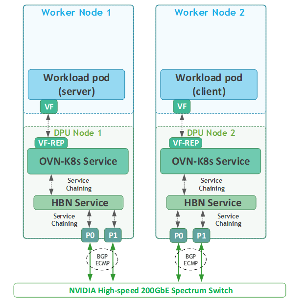
Performance Tests
RoCE Latency Test
-
Apply the following NetworkPolicy to enable stateless traffic:
Jump Node Console
kubectl apply -f stateless_netpolicy.yaml -
Create a test Deployment using the following YAML to create 2 replicas on 2 different worker nodes:
The container image specified below must include NVIDIA user space drivers and perftest
-
Apply the resource:
Jump Node Console
kubectl apply -f testapp-performance-test-deployment.yaml -
Validate that the deployment is running successfully:
Jump Node Console
$ kubectl get pods -o wide NAME READY STATUS RESTARTS AGE IP NODE NOMINATED NODE READINESS GATES testapp-performance-567cfdbd4b-7xzxm 1/1 Running 0 15s 10.233.68.3 worker2 <none> <none> testapp-performance-567cfdbd4b-m9vzc 1/1 Running 0 15s 10.233.67.3 worker1 <none> <none> -
Connect to one of the pods in the Deployment:
Jump Node Console
kubectl exec -it testapp-performance-567cfdbd4b-7xzxm -- bash -
From within the container, check its IP address on its interface and see that it is recognizable as an RDMA device:
First Pod Console
root@testapp-performance-567cfdbd4b-7xzxm:/# ip a 1: lo: <LOOPBACK,UP,LOWER_UP> mtu 65536 qdisc noqueue state UNKNOWN group default qlen 1000 link/loopback 00:00:00:00:00:00 brd 00:00:00:00:00:00 inet 127.0.0.1/8 scope host lo valid_lft forever preferred_lft forever inet6 ::1/128 scope host valid_lft forever preferred_lft forever 134: eth0: <BROADCAST,MULTICAST,UP,LOWER_UP> mtu 8940 qdisc mq state UP group default qlen 1000 link/ether 0a:58:0a:e9:44:03 brd ff:ff:ff:ff:ff:ff permaddr fa:85:f3:5f:a9:f7 altname enp137s0f0v4 inet 10.233.68.3/24 brd 10.233.68.255 scope global eth0 valid_lft forever preferred_lft forever inet6 fe80::f885:f3ff:fe5f:a9f7/64 scope link valid_lft forever preferred_lft forever root@testapp-performance-567cfdbd4b-7xzxm:/# rdma link | grep eth0 link mlx5_6/1 state ACTIVE physical_state LINK_UP netdev eth0 -
Start the
ib_read_latserver side:First Pod Console
root@testapp-performance-567cfdbd4b-7xzxm:/# ib_read_lat -F -n 20000 ************************************ * Waiting for client to connect... * ************************************ -
Using another console window, reconnect to the jump node and connect to the second pod in the deployment.
Jump Node Console
kubectl exec -it testapp-performance-567cfdbd4b-m9vzc -- bash -
From within the container, start the
ib_read_latclient (use the IP address from the server-side container) and check the latency results:First Pod Console
root@testapp-performance-567cfdbd4b-m9vzc:/# ib_read_lat -F -n 20000 10.233.68.3
---------------------------------------------------------------------------------------
                    RDMA_Read Latency Test
 Dual-port       : OFF          Device         : mlx5_14
 Number of qps   : 1            Transport type : IB
 Connection type : RC           Using SRQ      : OFF
 PCIe relax order: ON
 ibv_wr* API     : ON
 TX depth        : 1
 Mtu             : 4096[B]
 Link type       : Ethernet
 GID index       : 5
 Outstand reads  : 16
 rdma_cm QPs     : OFF
 Data ex. method : Ethernet
---------------------------------------------------------------------------------------
 local address: LID 0000 QPN 0x015f PSN 0xa2d513 OUT 0x10 RKey 0x044500 VAddr 0x00652c78a07000
 GID: 00:00:00:00:00:00:00:00:00:00:255:255:10:233:67:03
 remote address: LID 0000 QPN 0x016e PSN 0xe1afa9 OUT 0x10 RKey 0x048500 VAddr 0x00599c97d3c000
 GID: 00:00:00:00:00:00:00:00:00:00:255:255:10:233:68:03
---------------------------------------------------------------------------------------
 #bytes #iterations    t_min[usec]    t_max[usec]  t_typical[usec]    t_avg[usec]    t_stdev[usec]   99% percentile[usec]   99.9% percentile[usec]
 2       20000          3.94           8.33         4.04               4.68             0.72            7.60                    7.75
---------------------------------------------------------------------------------------
iPerf TCP Bandwidth Test
-
Create a test Deployment using the YAML from the previous example to create a pod on each worker that you can use to test TCP connectivity and performance.
The container image specified in the test must include iperf.
-
Connect to one of the pods in the deployment:
Jump Node Console
kubectl exec -it testapp-performance-567cfdbd4b-7xzxm -- bash -
Before starting the
iperf3server listeners, and to be able to achieve good results, check in another tab the cores the pod is currently running on:To be able to bind to specific cores, make sure to schedule a pod in Guaranteed QoS class.
-
Check on which worker node the pod is running on:
Jump Node Console
$ kubectl get pods -o wide | grep 7xzxm testapp-performance-567cfdbd4b-7xzxm 1/1 Running 0 10m 10.233.68.3 worker2 <none> <none> -
SSH to the worker:
Jump Node Console
depuser@jump:~$ ssh worker2 depuser@worker2:~$ sudo -i root@worker2:~# -
Inspect the pod current cores:
Worker2 Console
root@worker2:~# crictl ps | grep testapp a7f2268086471 032269a586520 10 minutes ago Running testapp-pod 0 89e06306373c1 testapp-performance-567cfdbd4b-7xzxm default root@worker2:~# crictl inspect a7f2268086471 | jq '.status.resources.linux.cpusetCpus' -
Output example:
Worker2 Console
"28-51"
-
-
Back within the container of the pod, use the following script to start multiple
iperf3servers (1 for each core) on different ports:iperf_server.sh
Bash#!/bin/bash # Cores to bind the iperf3 server processes to CORES=$1 # Calculate the first_core and last_core to provide the CPU range first_core=$(echo $CORES | cut -d "-" -f1) last_core=$(echo $CORES | cut -d "-" -f2) # Loop over the ports (5201 + i*2) for i in the given CPU range and run iperf3 servers for i in $(seq $first_core $last_core); do echo "Running iperf3 server on core $i" taskset -c $i iperf3 -s -p $((5201 + i * 2)) > /dev/null 2>&1 & done -
Start the script using the previous CPU range (leave 1 core as a buffer):
First Pod Console
root@testapp-performance-567cfdbd4b-7xzxm:/# chmod +x iperf_server.sh root@testapp-performance-567cfdbd4b-7xzxm:/# ./iperf_server.sh 28-50 Running iperf3 server on core 28 Running iperf3 server on core 29 ... ... Running iperf3 server on core 49 Running iperf3 server on core 50 root@testapp-performance-567cfdbd4b-7xzxm:/# ps -ef | grep iperf3 root 39 1 0 13:57 pts/1 00:00:00 iperf3 -s -p 5257 root 40 1 0 13:57 pts/1 00:00:00 iperf3 -s -p 5259 ... ... root 60 1 0 13:57 pts/1 00:00:00 iperf3 -s -p 5299 root 61 1 0 13:57 pts/1 00:00:00 iperf3 -s -p 5301 -
Connect to the second pod:
Jump Node Console
kubectl exec -it testapp-performance-567cfdbd4b-m9vzc -- bash -
Follow the previously displayed method to identify the CPU cores the second pod is running on.
-
Use the following script to start multiple
iperf3clients that will connect to eachiperf3server in the first pod:-
The script receives 3 parameters: server IP to connect to, the cores it will spawn the
iperf3processes to, and the duration theiperf3test will run. Make sure to pass all 3 when initiating the script and providing the CPU cores as a range (28-50 in this example). -
jqandbcshould be installed on the pod to properly run it.
iperf_client.sh
Bash#!/bin/bash # IP address of the server where iperf3 servers are running SERVER_IP=$1 # Change to your server's IP # Cores to bind the iperf3 client processes to CORES=$2 # Duration to run the iperf3 test DUR=$3 # Variable to accumulate the total bandwidth in Gbit/sec total_bandwidth_Gbit=0 # Calculate the first_core and last_core to provide the CPU range first_core=$(echo $CORES | cut -d "-" -f1) last_core=$(echo $CORES | cut -d "-" -f2) # Array to store the PIDs of background tasks pids=() # Loop over the ports (5201 + i*2) for i in the given CPU range for i in $(seq $first_core $last_core); do port=$((5201 + i * 2)) cpu_core=$i # Assign CPU core based on the value of i output_file="iperf3_client_results_$port.log" # Run the iperf3 client in the background with CPU core binding timeout $(( DUR +5 )) taskset -c $cpu_core iperf3 -c $SERVER_IP -p $port -t $DUR -Z -J > $output_file & pid=$! pids+=("$pid") done # Wait for all background tasks to complete and check their status for pid in "${pids[@]}"; do wait $pid if [[ $? -ne 0 ]]; then echo "Process with PID $pid failed or timed out." fi done # Summarize the results from each log file echo "Summary of iperf3 client results:" for i in $(seq $first_core $last_core); do port=$((5201 + i * 2)) output_file="iperf3_client_results_$port.log" if [[ -f $output_file ]]; then echo "Results for port $port:" # Parse the results and print a summary bandwidth_bps=$(jq '.end.sum_received.bits_per_second' $output_file) if [[ -n $bandwidth_bps ]]; then # Convert bandwidth from bps to Gbit/sec bandwidth_Gbit=$(echo "scale=3; $bandwidth_bps / 1000000000" | bc) echo " Bandwidth: $bandwidth_Gbit Gbit/sec" # Accumulate the bandwidth for the total summary total_bandwidth_Gbit=$(echo "scale=3; $total_bandwidth_Gbit + $bandwidth_Gbit" | bc) # Delete current log file rm $output_file else echo "No bandwidth data found in $output_file" fi else echo "No results found for port $port" fi done # Print the total bandwidth summary echo "Total Bandwidth across all streams: $total_bandwidth_Gbit Gbit/sec" -
-
Run the script and check the performance results:
Second Pod Console
root@testapp-performance-567cfdbd4b-m9vzc:/# chmod +x iperf_client.sh
root@testapp-performance-567cfdbd4b-m9vzc:/# ./iperf_client.sh 10.233.68.3 28-50 30
Summary of iperf3 client results:
Results for port 5257:
  Bandwidth: 10.299 Gbit/sec
Results for port 5259:
  Bandwidth: 14.417 Gbit/sec
Results for port 5261:
  Bandwidth: 26.517 Gbit/sec
Results for port 5263:
  Bandwidth: 14.869 Gbit/sec
Results for port 5265:
  Bandwidth: 6.053 Gbit/sec
Results for port 5267:
  Bandwidth: 29.648 Gbit/sec
Results for port 5269:
  Bandwidth: 16.708 Gbit/sec
Results for port 5271:
  Bandwidth: 5.970 Gbit/sec
Results for port 5273:
  Bandwidth: 10.411 Gbit/sec
Results for port 5275:
  Bandwidth: 31.203 Gbit/sec
Results for port 5277:
  Bandwidth: 14.025 Gbit/sec
Results for port 5279:
  Bandwidth: 30.534 Gbit/sec
Results for port 5281:
  Bandwidth: 13.452 Gbit/sec
Results for port 5283:
  Bandwidth: 6.014 Gbit/sec
Results for port 5285:
  Bandwidth: 25.819 Gbit/sec
Results for port 5287:
  Bandwidth: 26.472 Gbit/sec
Results for port 5289:
  Bandwidth: 5.940 Gbit/sec
Results for port 5291:
  Bandwidth: 10.068 Gbit/sec
Results for port 5293:
  Bandwidth: 5.981 Gbit/sec
Results for port 5295:
  Bandwidth: 13.352 Gbit/sec
Results for port 5297:
  Bandwidth: 29.973 Gbit/sec
Results for port 5299:
  Bandwidth: 13.464 Gbit/sec
Results for port 5301:
  Bandwidth: 31.478 Gbit/sec
Total Bandwidth across all streams: 392.667 Gbit/sec
Connecting to BlueMan Web Interface
As part of the DPF system installation, DTS and Blueman DPUServices were deployed.
DOCA Telemetry Service (DTS) collects data from built-in providers (data providers such as sysfs, ethtool and tc, and aggregation providers such as fluent_aggr and prometheus_aggr), and from external telemetry applications.
DOCA BlueMan runs in the DPU as a standalone web dashboard and consolidates all the basic information, health, and telemetry counters into a single interface.
All the information that BlueMan provides is gathered from the DOCA Telemetry Service (DTS).
To be able to log into BlueMan and view the local DTS instance data in a convenient way, the management IP address of the DPU should be entered to a web browser located in the same network as the DPU. In this RDG, it will be demonstrated by using VNC to connect to the jump node and opening a web browser in it (same as with MaaS, Firewall).
-
To find out the DPU management IP address in the
10.0.110.0/24subnet, obtain the DPU names:Jump Node Console
$ kubectl get dpus -n dpf-operator-system NAME READY PHASE AGE worker1-mt2404xz0c97 True Ready 74m worker2-mt2333xz0xvb True Ready 71m -
Obtain the DPU management IPs:
Jump Node Console
$ kubectl get dpus -n dpf-operator-system -o json | jq '.items[].status.addresses[0].address' | cut -d '"' -f2 10.0.110.88 10.0.110.89 -
In the VNC session, open a web browser and enter https://<DPU_INTERNAL_IP>. A warning of self-signed certificate should appear; click accept the risk and proceed.
Afterwards it will open the login page:
The login credentials to use are the same pair used for the SSH connection to the DPU (ubuntu/ubuntu). However, login straight away won't work and an additional certificate exception in the browser has to be made. -
Open another tab in the browser and enter https://<DPU_INTERNAL_IP>:10000. It will again prompt a warning of self-signed certificate; click accept the risk to add it to your browser exception list.
-
Return to the BlueMan login page, enter the credentials, and you should be able to login.
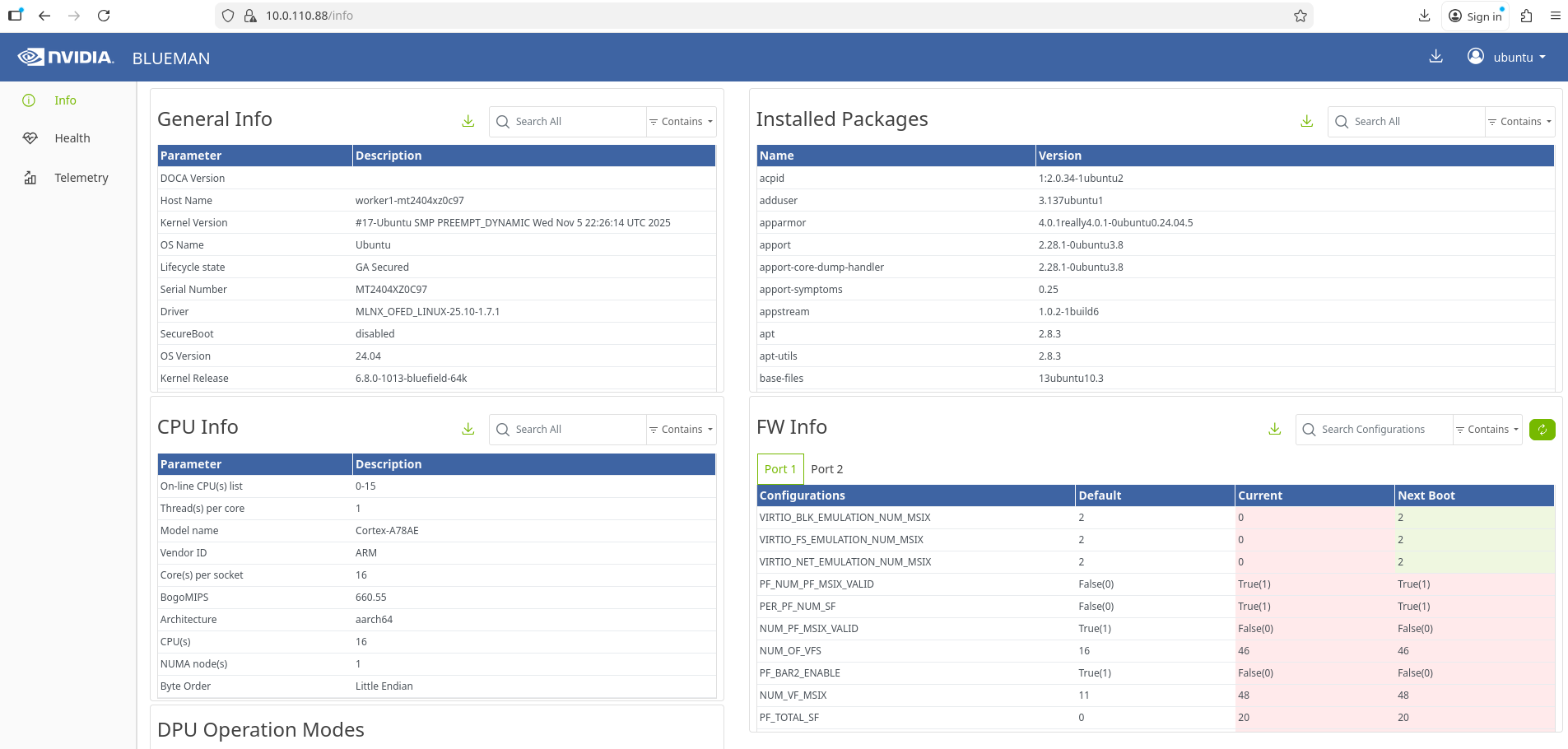
Authors

|
Guy Zilberman Guy Zilberman is a solution architect at NVIDIA's Networking Solutions Labs, bringing extensive experience from several leadership roles in cloud computing. He specializes in designing and implementing solutions for cloud and containerized workloads, leveraging NVIDIA's advanced networking technologies. His work primarily focuses on open-source cloud infrastructure, with expertise in platforms such as Kubernetes (K8s) and OpenStack. |
Last updated: