Created Sep 08, 2025
Updated May 15 2026 (v26.4 GA)
Scope
This Reference Deployment Guide (RDG) provides comprehensive instructions for deploying the NVIDIA DOCA Platform Framework (DPF) on high-performance, bare-metal infrastructure in Zero-Trust mode. It focuses on the setup and use of DPU-based services on NVIDIA® BlueField®-3 DPUs to deliver secure, isolated, and hardware-accelerated environments.
The guide is intended for experienced system administrators, systems engineers, and solution architects who build highly secure bare-metal environments using NVIDIA BlueField DPUs for acceleration, isolation, and infrastructure offload.
-
This reference implementation, as the name implies, is a specific, opinionated deployment example designed to address the use case described above.
-
Although other approaches may exist for implementing similar solutions, this document provides a detailed guide for this specific method.
Abbreviations and Acronyms
|
Term |
Definition |
Term |
Definition |
|---|---|---|---|
|
BFB |
BlueField Bootstream |
NGC |
NVIDIA GPU Cloud |
|
DOCA |
Data Center Infrastructure-on-a-Chip Architecture |
NFS |
Network File System |
|
DPF |
DOCA Platform Framework |
OOB |
Out-of-Band |
|
DPU |
Data Processing Unit |
PF |
Physical Function |
|
K8S |
Kubernetes |
RDG |
Reference Deployment Guide |
|
KVM |
Kernel-based Virtual Machine |
RDMA |
Remote Direct Memory Access |
|
MAAS |
Metal as a Service |
RoCE |
RDMA over Converged Ethernet |
|
MTU |
Maximum Transmission Unit |
ZT |
Zero Trust |
Introduction
The NVIDIA BlueField-3 Data Processing Unit (DPU) is a 400 Gb/s infrastructure compute platform designed for line-rate processing of software-defined networking, storage, and cybersecurity workloads. It combines powerful compute resources, high-speed networking, and advanced programmability to deliver hardware-accelerated, software-defined solutions for modern data centers.
NVIDIA DOCA unleashes the full potential of the BlueField platform by enabling rapid development of applications and services that offload, accelerate, and isolate data center workloads.
However, deploying and managing DPUs, especially at scale, presents operational challenges. Without a robust provisioning and orchestration system, tasks such as lifecycle management, service deployment, and network configuration for service function chaining (SFC) can quickly become complex and error prone. This is where the DOCA Platform Framework (DPF) comes into play.
DPF automates the full DPU lifecycle, and simplifies advanced network configurations. With DPF, services can be deployed seamlessly, allowing for efficient offloading and intelligent routing of traffic through the DPU data plane.
By leveraging DPF, users can scale and automate DPU management across Bare Metal, Virtual, and Kubernetes customer environments - optimizing performance while simplifying operations.
DPF supports multiple deployment models. This guide focuses on the Zero Trust bare-metal deployment model. In this scenario:
-
The DPU is managed through its Baseboard Management Controller (BMC)
-
All management traffic occurs over the DPU's out-of-band (OOB) network
-
The host is considered as an untrusted entity towards the data center network. The DPU acts as a barrier between the host and the network.
-
The host sees the DPU as a standard NIC, with no access to the internal DPU management plane (Zero Trust Mode)
This Reference Deployment Guide (RDG) provides a step-by-step example for installing DPF in Zero-Trust mode. It also includes practical demonstrations of performance optimization, validated using standard RDMA and TCP workloads.
As part of the reference implementation, open-source components outside the scope of DPF (e.g., MAAS, pfSense, Kubespray) are used to simulate a realistic customer deployment environment. The guide includes the full end-to-end deployment process, including:
-
Infrastructure provisioning
-
DPF deployment
-
DPU provisioning (redfish)
-
Service configuration and deployment
-
Service chaining.
References
Solution Architecture
Key Components and Technologies
-
NVIDIA BlueField® Data Processing Unit (DPU)
The NVIDIA® BlueField® data processing unit (DPU) ignites unprecedented innovation for modern data centers and supercomputing clusters. With its robust compute power and integrated software-defined hardware accelerators for networking, storage, and security, BlueField creates a secure and accelerated infrastructure for any workload in any environment, ushering in a new era of accelerated computing and AI.
-
NVIDIA DOCA Software Framework
NVIDIA DOCA™ unlocks the potential of the NVIDIA® BlueField® networking platform. By harnessing the power of BlueField DPUs and SuperNICs, DOCA enables the rapid creation of applications and services that offload, accelerate, and isolate data center workloads. It lets developers create software-defined, cloud-native, DPU- and SuperNIC-accelerated services with zero-trust protection, addressing the performance and security demands of modern data centers.
-
NVIDIA ConnectX SmartNICs
10/25/40/50/100/200 and 400G Ethernet Network Adapters
The industry-leading NVIDIA® ConnectX® family of smart network interface cards (SmartNICs) offer advanced hardware offloads and accelerations.
NVIDIA Ethernet adapters enable the highest ROI and lowest Total Cost of Ownership for hyperscale, public and private clouds, storage, machine learning, AI, big data, and telco platforms.
-
NVIDIA LinkX Cables
The NVIDIA® LinkX® product family of cables and transceivers provides the industry’s most complete line of 10, 25, 40, 50, 100, 200, and 400GbE in Ethernet and 100, 200 and 400Gb/s InfiniBand products for Cloud, HPC, hyperscale, Enterprise, telco, storage and artificial intelligence, data center applications.
-
NVIDIA Spectrum Ethernet Switches
Flexible form-factors with 16 to 128 physical ports, supporting 1GbE through 400GbE speeds.
Based on a ground-breaking silicon technology optimized for performance and scalability, NVIDIA Spectrum switches are ideal for building high-performance, cost-effective, and efficient Cloud Data Center Networks, Ethernet Storage Fabric, and Deep Learning Interconnects.
NVIDIA combines the benefits of NVIDIA Spectrum™ switches, based on an industry-leading application-specific integrated circuit (ASIC) technology, with a wide variety of modern network operating system choices, including NVIDIA Cumulus® Linux, SONiC and NVIDIA Onyx®.
-
NVIDIA Cumulus Linux
NVIDIA® Cumulus® Linux is the industry's most innovative open network operating system that allows you to automate, customize, and scale your data center network like no other.
-
Kubernetes
Kubernetes is an open-source container orchestration platform for deployment automation, scaling, and management of containerized applications.
-
Kubespray
Kubespray is a composition ofAnsible
playbooks, inventory, provisioning tools, and domain knowledge for generic OS/Kubernetes clusters configuration management tasks and provides:
-
A highly available cluster
-
Composable attributes
-
Support for most popular Linux distributions
-
Solution Design
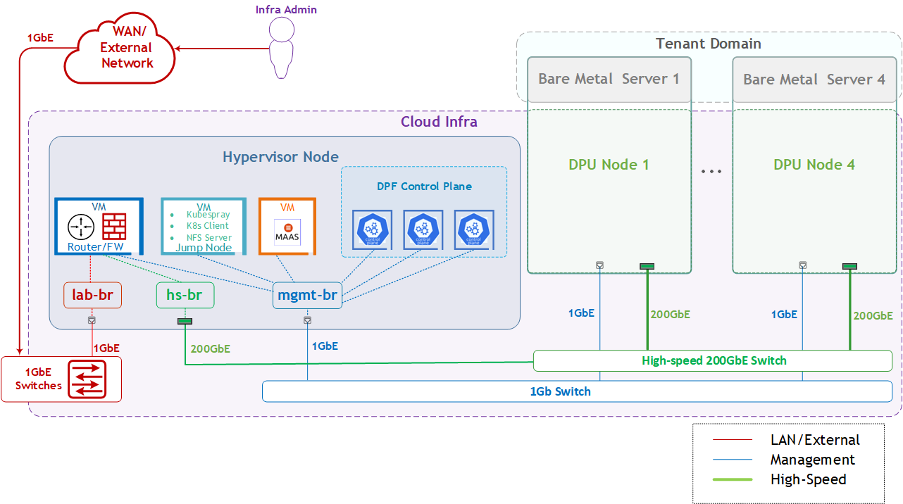
Solution Logical Design
The logical design includes the following components:
-
1 x Hypervisor node (KVM-based) with ConnectX-7:
-
1 x Firewall VM
-
1 x Jump Node VM
-
1 x MaaS VM
-
3 x K8s Master VMs running all K8s management components
-
-
4 x Worker nodes (PCI Gen5), each with a 1 x BlueField-3 NIC
-
Single High-Speed (HS) switch
-
1 Gb Host Management network
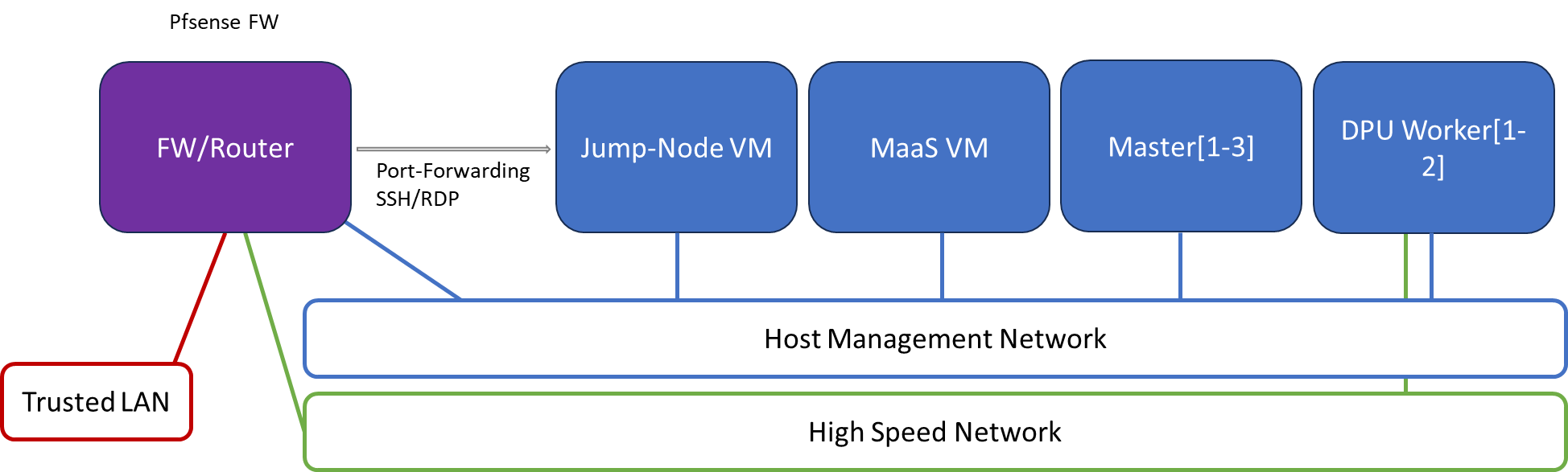
Firewall Design
The pfSense firewall in this solution serves a dual purpose:
-
Firewall—provides an isolated environment for the DPF system, ensuring secure operations
-
Router—enables Internet access for the management network
Port-forwarding rules for SSH and RDP are configured on the firewall to route traffic to the jump node’s IP address in the host management network. From the jump node, administrators can manage and access various devices in the setup, as well as handle the deployment of the Kubernetes (K8s) cluster and DPF components.
The following diagram illustrates the firewall design used in this solution:
Software Stack Components
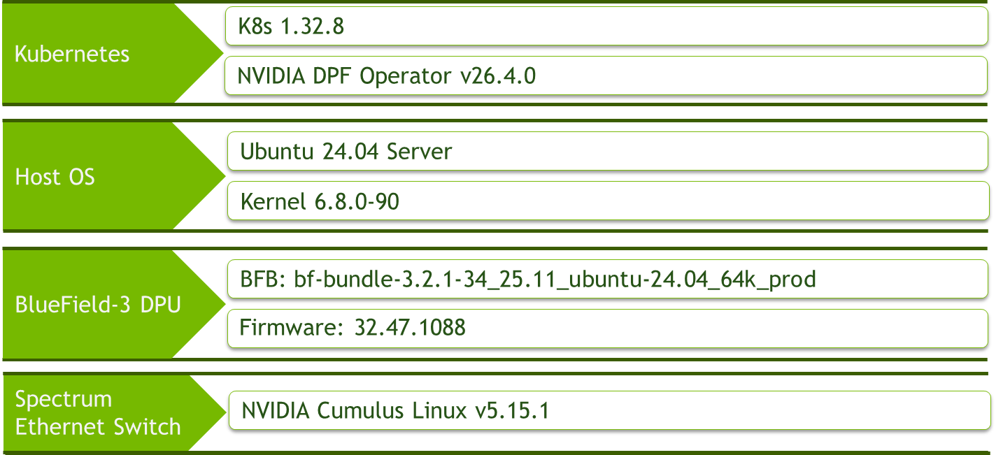
Make sure to use the exact same versions for the software stack as described above.
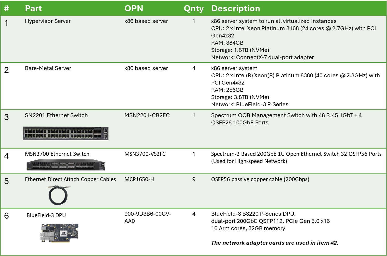
Bill of Materials
Deployment and Configuration
Node and Switch Definitions
These are the definitions and parameters used for deploying the demonstrated fabric:
|
Switches Ports Usage |
||
|---|---|---|
|
Hostname |
Rack ID |
Ports |
|
|
1 |
swp1-5 |
|
|
1 |
swp1-9 |
|
Hosts |
|||||
|---|---|---|---|---|---|
|
Rack |
Server Type |
Server Name |
Switch Port |
IP and NICs |
Default Gateway |
|
Rack1
|
Hypervisor Node |
|
mgmt-switch: hs-switch: |
lab-br (interface eno1): Trusted LAN IP mgmt-br (interface eno2): - hs-br (interface enp1s0): - |
Trusted LAN GW |
|
Rack1 |
Firewall (Virtual) |
|
- |
WAN (lab-br): Trusted LAN IP LAN (mgmt-br): 10.0.110.254/24 OPT1(hs-br): 172.169.50.1/30 |
Trusted LAN GW |
|
Rack1 |
Jump Node (Virtual) |
|
- |
enp1s0: 10.0.110.253/24 |
10.0.110.254 |
|
Rack1 |
MaaS (Virtual) |
|
- |
enp1s0: 10.0.110.252/24 |
10.0.110.254 |
|
Rack1 |
Master Node
|
|
- |
enp1s0: 10.0.110.1/24 |
10.0.110.254 |
|
Rack1 |
Master Node
|
|
- |
enp1s0: 10.0.110.2/24 |
10.0.110.254 |
|
Rack1 |
Master Node
|
|
- |
enp1s0: 10.0.110.3/24 |
10.0.110.254 |
|
Rack1
|
Worker Node |
|
mgmt-switch: hs-switch: |
dpubmc: 10.0.110.201/24
ens1f0np0/ens1f1np1: 10.0.120.0/22 |
10.0.110.254 |
|
Rack1
|
Worker Node |
|
mgmt-switch: hs-switch: |
dpubmc: 10.0.110.202/24
ens1f0np0/ens1f1np1: 10.0.120.0/22 |
10.0.110.254 |
|
Rack1
|
Worker Node |
|
mgmt-switch: hs-switch: |
dpubmc: 10.0.110.203/24
ens1f0np0/ens1f1np1: 10.0.120.0/22 |
10.0.110.254 |
|
Rack1
|
Worker Node |
|
mgmt-switch: hs-switch: |
dpubmc: 10.0.110.204/24
ens1f0np0/ens1f1np1: 10.0.120.0/22 |
10.0.110.254 |
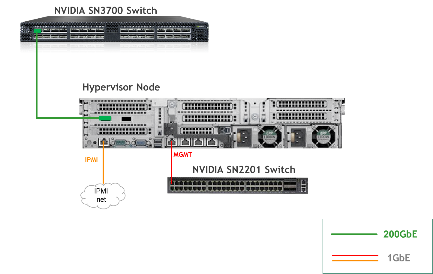
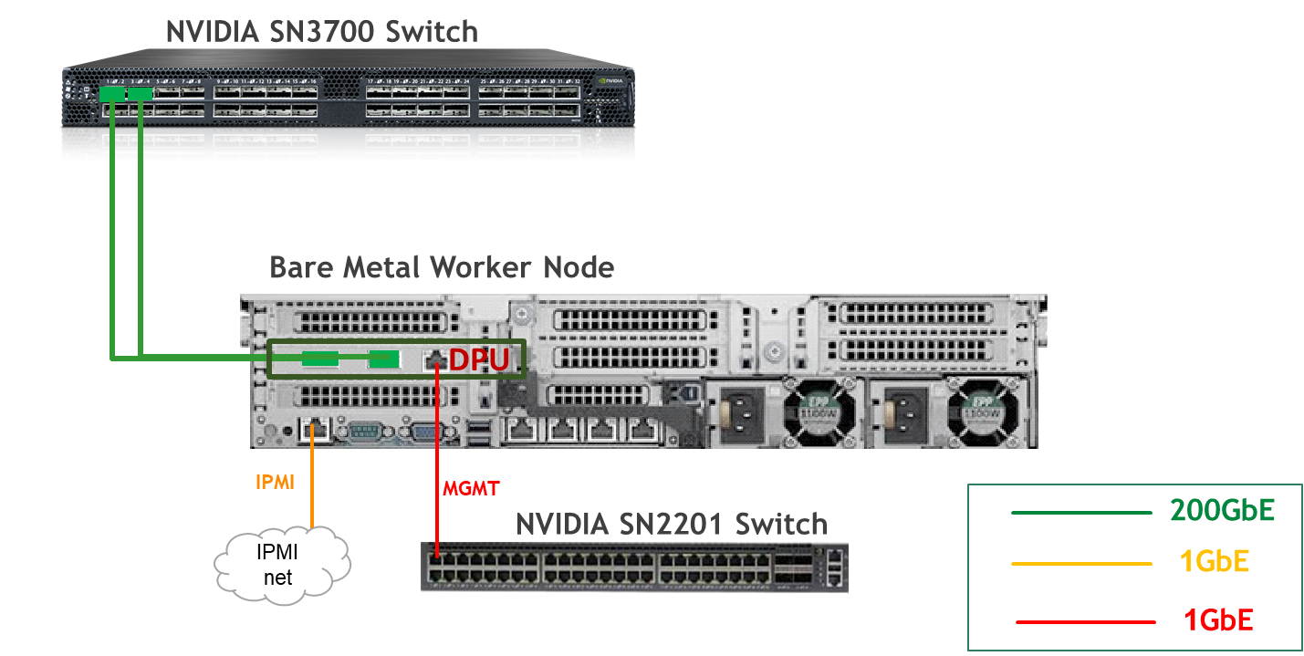
Wiring
Hypervisor Node
Bare Metal Worker Node
Fabric Configuration
Updating Cumulus Linux
As a best practice, make sure to use the latest released Cumulus Linux NOS version.
For information on how to upgrade Cumulus Linux, refer to the Cumulus Linux User Guide.
Configuring the Cumulus Linux Switch
The SN3700 switch (hs-switch), is configured as follows:
The SN2201 switch (mgmt-switch) is configured as follows:
Host Configuration
Make sure that the BIOS settings on the worker node servers have SR-IOV enabled and that the servers are tuned for maximum performance.
All worker nodes must have the same PCIe placement for the BlueField-3 NIC and must display the same interface name.
Make sure that you have DPU BMC and OOB MAC addresses.
Hypervisor Installation and Configuration
The hypervisor used in this Reference Deployment Guide (RDG) is based on Ubuntu 24.04 with KVM.
While this document does not detail the KVM installation process, it is important to note that the setup requires the following ISOs to deploy the Firewall, Jump, and MaaS virtual machines (VMs):
-
Ubuntu 24.04
-
pfSense-CE-2.7.2
To implement the solution, three Linux bridges must be created on the hypervisor:
Ensure a DHCP record is configured for the lab-br bridge interface in your trusted LAN to assign it an IP address.
-
lab-br– connects the Firewall VM to the trusted LAN. -
mgmt-br– Connects the various VMs to the host management network. -
hs-br– Connects the Firewall VM to the high-speed network.
Additionally, an MTU of 9000 must be configured on the management and high-speed bridges (mgmt-br and hs-br) as well as their uplink interfaces to ensure optimal performance.
Hypervisor netplan configuration
network:
    ethernets:
        eno1:
            dhcp4: false
        eno2:
            dhcp4: false
            mtu: 9000
        ens2f0np0:
            dhcp4: false
            mtu: 9000
    bridges:
      lab-br:
         interfaces: [eno1]
         dhcp4: true
      mgmt-br:
         interfaces: [eno2]
         dhcp4: false
         mtu: 9000
      hs-br:
         interfaces: [ens2f0np0]
         dhcp4: false
         mtu: 9000
    version: 2
Apply the configuration:
Hypervisor Console
$ sudo netplan apply
Prepare Infrastructure Servers
Firewall VM - pfSense Installation and Interface Configuration
Download the pfSense CE (Community Edition) ISO to your hypervisor and proceed with the software installation.
Suggested spec:
-
vCPU: 2
-
RAM: 2GB
-
Storage: 10GB
-
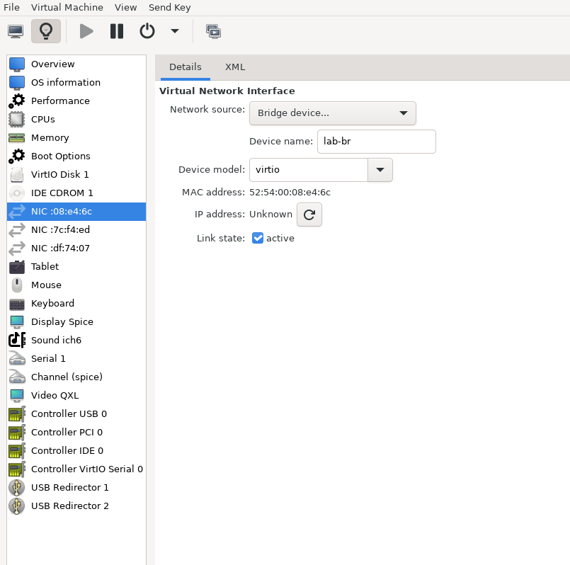
Network interfaces
-
Bridge device connected to
lab-br -
Bridge device connected to
mgmt-br -
Bridge device connected to
hs-br
-
The Firewall VM must be connected to all three Linux bridges on the hypervisor. Before beginning the installation, ensure that three virtual network interfaces of type "Bridge device" are configured. Each interface should be connected to a different bridge (lab-br, mgmt-br, and hs-br) as illustrated in the diagram below.
After completing the installation, the setup wizard displays a menu with several options, such as "Assign Interfaces" and "Reboot System." During this phase, you must configure the network interfaces for the Firewall VM.
-
Select Option 2: "Set interface(s) IP address" and configure the interfaces as follows:
-
WAN (lab-br) – Trusted LAN IP (Static/DHCP)
-
LAN (mgmt-br) – Static IP
10.0.110.254/24 -
OPT1 (hs-br) – Static IP
10.0.123.254/22
-
-
Once the interface configuration is complete, use a web browser within the host management network to access the Firewall web interface and finalize the configuration.
Next, proceed with installing the Jump VM. This VM serves as a platform for running a browser for accessing the firewall’s web interface (UI) for post-installation configuration.
Jump VM
Suggested specifications:
-
vCPU: 4
-
RAM: 8GB
-
Storage: 100GB
-
Network interface: Bridge device, connected to
mgmt-br
Procedure:
-
Proceed with a standard Ubuntu 24.04 installation. Use the following login credentials across all hosts in this setup:
Username
Password
depuser
user
-
Enable internet connectivity and DNS resolution by creating the following Netplan configuration:
Use
10.0.110.254as a temporary DNS nameserver until the MaaS VM is installed and configured. After completing the MaaS installation, update the Netplan file to replace this address with the MaaS IP:10.0.110.252.
Jump Node netplan
YAMLnetwork: ethernets: enp1s0: dhcp4: false addresses: [10.0.110.253/24] nameservers: search: [dpf.rdg.local.domain] addresses: [10.0.110.254] routes: - to: default via: 10.0.110.254 version: 2 -
Apply the configuration:
Jump Node Console
depuser@jump:~$ sudo netplan apply -
Update and upgrade the system:
Jump Node Console
depuser@jump:~$ sudo apt update -y depuser@jump:~$ sudo apt upgrade -y -
Install and configure the Xfce desktop environment and XRDP (complementary packages for RDP):
Jump Node Console
depuser@jump:~$ sudo apt install -y xfce4 xfce4-goodies depuser@jump:~$ sudo apt install -y lightdm-gtk-greeter depuser@jump:~$ sudo apt install -y xrdp depuser@jump:~$ echo "xfce4-session" | tee .xsession depuser@jump:~$ sudo systemctl restart xrdp -
Install and configure the Xfce desktop environment and TigerVNC (VNC remote access):
-
Install the required packages:
Jump Node Console
depuser@jump:~$ sudo apt-get update depuser@jump:~$ sudo apt-get -y install tigervnc-standalone-server tigervnc-scraping-server tigervnc-tools xfce4 xfce4-goodies dbus-x11 -
Set Xfce as the X session and create the VNC password for depuser:
Jump Node Console
depuser@jump:~$ echo "xfce4-session" | tee ~/.xsession depuser@jump:~$ chmod +x ~/.xsession depuser@jump:~$ vncpasswd -
Map VNC display :1 to depuser (the systemd template unit reads this file to know which user is bound to which display):
Jump Node Console
depuser@jump:~$ sudo tee /etc/tigervnc/vncserver.users > /dev/null <<'EOF' :1=depuser EOF -
Create the systemd template unit that runs the official TigerVNC vncserver wrapper on every start/reboot (the wrapper handles PID files, prior-session cleanup, and starts xfce4 via -xstartup):
Jump Node Console
depuser@jump:~$ sudo tee /etc/systemd/system/vncserver@.service > /dev/null <<'EOF' [Unit] Description=Start TigerVNC server at startup After=syslog.target network.target [Service] Type=forking User=depuser Group=depuser WorkingDirectory=/home/depuser PIDFile=/home/depuser/.vnc/%H%i.pid ExecStartPre=-/usr/bin/vncserver -kill %i > /dev/null 2>&1 || : ExecStart=/usr/bin/vncserver -xstartup /usr/bin/startxfce4 -SecurityTypes VncAuth,TLSVnc -geometry 1920x1080 -localhost no -nolisten tcp %i ExecStop=/usr/bin/vncserver -kill %i > /dev/null 2>&1 || : [Install] WantedBy=multi-user.target EOF -
Enable the service and start it now (display :1 binds to TCP port 5901; the service starts immediately and on every subsequent reboot):
Jump Node Console
depuser@jump:~$ sudo systemctl daemon-reload depuser@jump:~$ sudo systemctl enable --now vncserver@:1.service depuser@jump:~$ sudo systemctl status vncserver@:1.service -
Verify that VNC is listening on port 5901:
Jump Node Console
depuser@jump:~$ ss -tlnp | grep 5901 -
Connect a VNC viewer (TigerVNC Viewer, RealVNC, Remmina) to
<jump-ip>:1using the password set withvncpasswdvncpasswd.
-
-
Install Firefox for accessing the Firewall web interface:
Jump Node Console
$ sudo apt install -y firefox -
Install and configure an NFS server with the
/mnt/dpf_sharedirectory:Jump Node Console
sudo apt install -y nfs-server $ sudo mkdir -m 777 /mnt/dpf_share $ sudo vi /etc/exports -
Add the following line to
/etc/exports:Jump Node Console
/mnt/dpf_share 10.0.110.0/24(rw,sync,no_subtree_check) -
Restart the NFS server:
Jump Node Console
$ sudo systemctl restart nfs-server -
Create the directory
bfbunder/mnt/dpf_sharewith the same permissions as the parent directory:Jump Node Console
$ sudo mkdir -m 777 /mnt/dpf_share/bfb -
Generate an SSH key pair for
depuserin the jump node (later on will be imported to the admin user in MaaS to enable password-less login to the provisioned servers):Jump Node Console
depuser@jump:~$ ssh-keygen -t rsa -
Reboot the jump node to display the graphical user interface:
Jump Node Console
depuser@jump:~$ sudo rebootAfter setting up port-forwarding rules on the firewall (next steps), remote login to the graphical interface of the Jump node will be available.
Concurrent login to the local graphical console and using RDP isn't possible, make sure to first log out from the local console when switching to RDP connection.
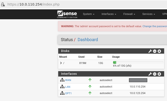
Firewall VM – Web Configuration
From your Jump node, open a Firefox web browser and navigate to the pfSense web UI (http://10.0.110.254. The default login credentials are admin/pfsense). The login page should appear as follows:
The IP addresses from the trusted LAN network under "DNS servers" and "Interfaces - WAN" are blurred.
Proceed with the following configurations:
The following screenshots display only a part of the configuration view. Make sure to not miss any of the steps mentioned below!
-
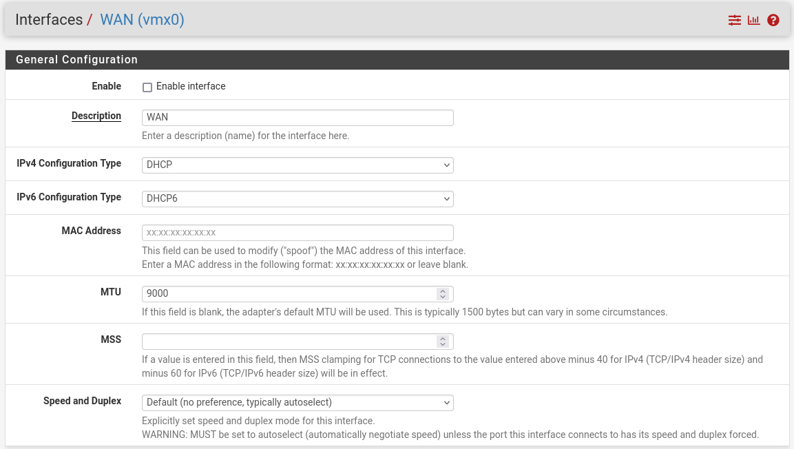
Interfaces:
-
WAN (lab-br) – mark “Enable interface”, unmark “Block private networks and loopback addresses”
-
-
-
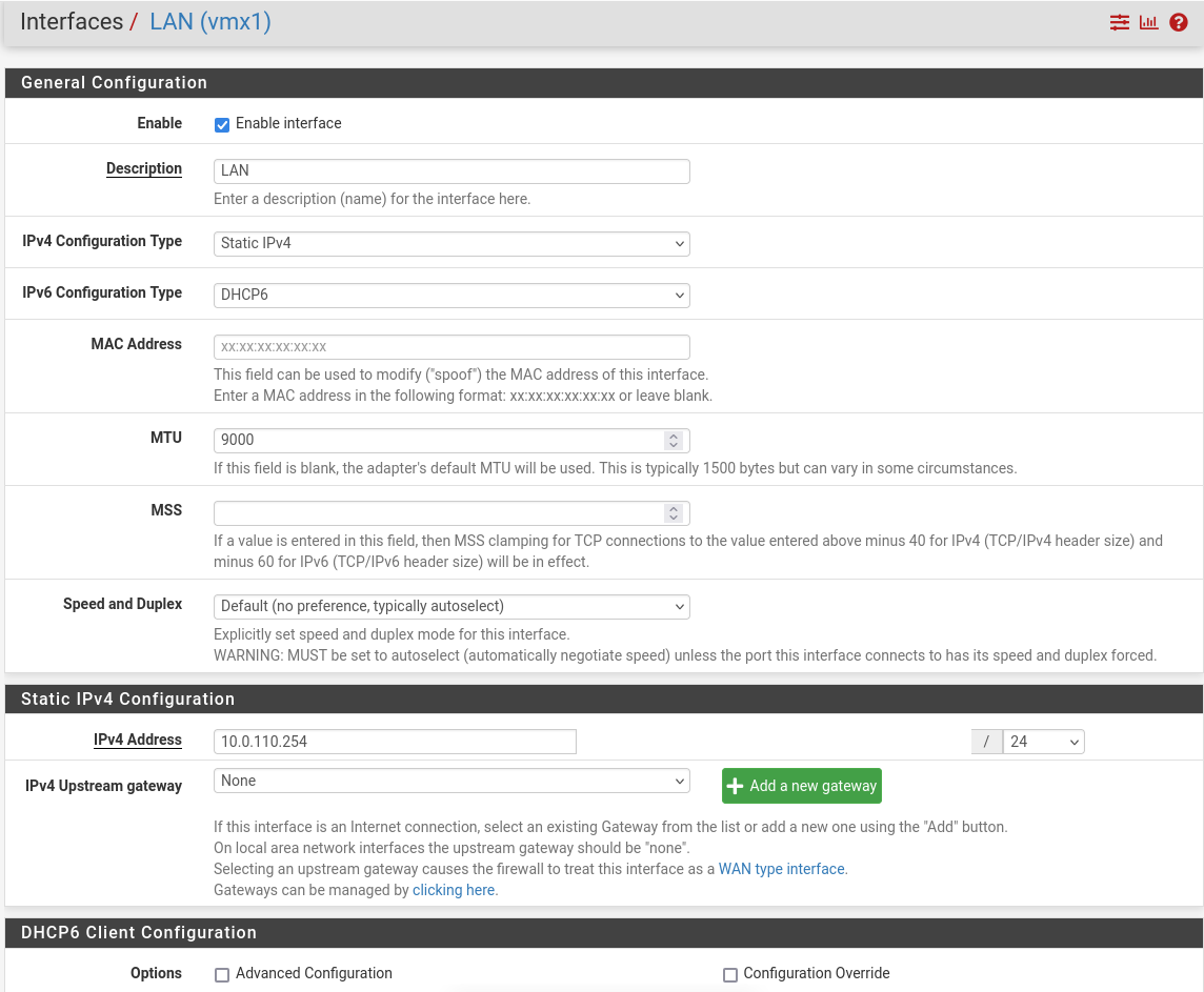
LAN (mgmt-br) – mark “Enable interface”, “IPv4 configuration type”: Static IPv4 ("IPv4 Address": 10.0.110.254/24, "IPv4 Upstream Gateway": None), “MTU”: 9000
-
-
-
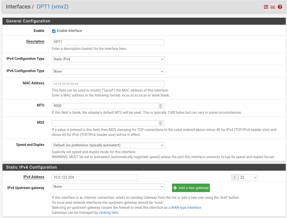
OPT1 (hs-br) – mark “Enable interface”, “IPv4 configuration type”: Static IPv4 ("IPv4 Address": 10.0.123.254/22, "IPv4 Upstream Gateway": None), “MTU”: 9000
-
-
Firewall:
-
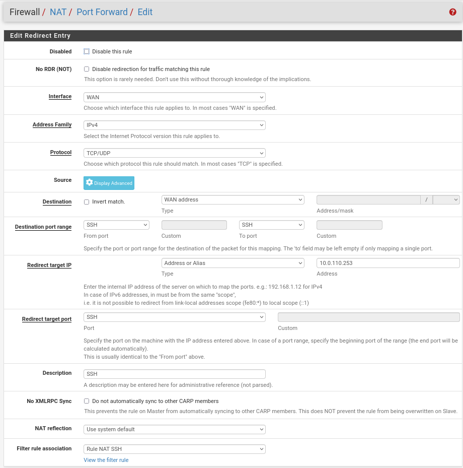
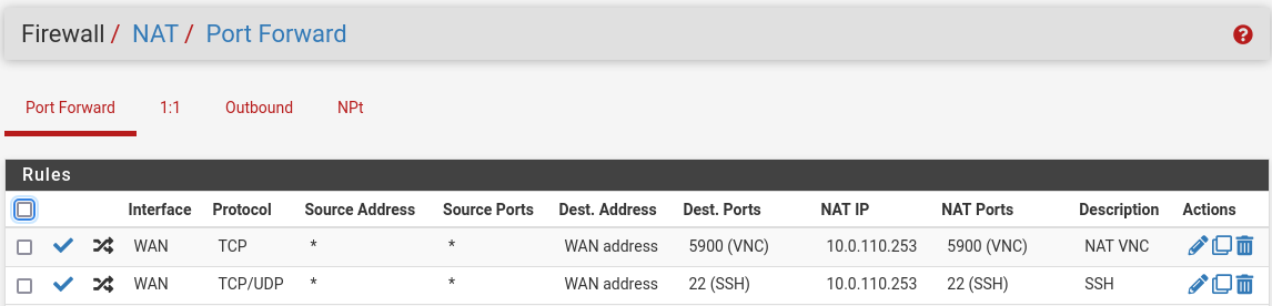
NAT -> Port Forward -> Add rule -> “Interface”: WAN, “Address Family”: IPv4, “Protocol”: TCP, “Destination”: WAN address, “Destination port range”: (“From port”: SSH, “To port”: SSH), “Redirect target IP”: (“Type”: Address or Alias, “Address”: 10.0.110.253), “Redirect target port”: SSH, “Description”: NAT SSH
-
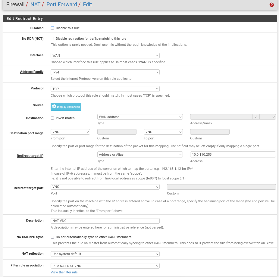
NAT -> Port Forward -> Add rule -> “Interface”: WAN, “Address Family”: IPv4, “Protocol”: TCP, “Destination”: WAN address, “Destination port range”: (“From port”: VNC, “To port”: VNC), “Redirect target IP”: (“Type”: Address or Alias, “Address”: 10.0.110.253), “Redirect target port”: NAT VNC, “Description”: NAT VNC
-
-
-
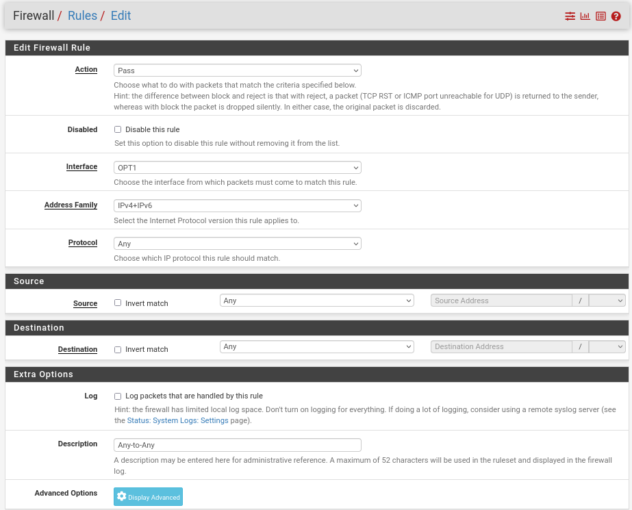
Rules -> OPT1 -> Add rule -> “Action”: Pass, “Interface”: OPT1, “Address Family”: IPv4+IPv6, “Protocol”: Any, “Source”: Any, “Destination”: Any
-
MaaS VM
Suggested specifications:
-
vCPU: 4
-
RAM: 4 GB
-
Storage: 100 GB
-
Network interface: Bridge device, connected to
mgmt-br
Procedure:
-
Perform a regular Ubuntu installation on the MaaS VM.
-
Create the following Netplan configuration to enable internet connectivity and DNS resolution:
Use
10.0.110.254as a temporary DNS nameserver. After the MaaS installation, replace this with the MaaS IP address (10.0.110.252) in both the Jump and MaaS VM Netplan files.
MaaS netplan
YAMLnetwork: ethernets: enp1s0: dhcp4: false addresses: [10.0.110.252/24] nameservers: search: [dpf.rdg.local.domain] addresses: [10.0.110.254] routes: - to: default via: 10.0.110.254 version: 2 -
Apply the netplan configuration:
MaaS Console
depuser@maas:~$ sudo netplan apply -
Update and upgrade the system:
MaaS Console
depuser@maas:~$ sudo apt update -y depuser@maas:~$ sudo apt upgrade -y -
Install PostgreSQL and configure the database for MaaS:
MaaS Console
$ sudo -i # apt install -y postgresql # systemctl disable --now systemd-timesyncd # export MAAS_DBUSER=maasuser # export MAAS_DBPASS=maaspass # export MAAS_DBNAME=maas # sudo -i -u postgres psql -c "CREATE USER \"$MAAS_DBUSER\" WITH ENCRYPTED PASSWORD '$MAAS_DBPASS'" # sudo -i -u postgres createdb -O "$MAAS_DBUSER" "$MAAS_DBNAME" -
Install MaaS:
MaaS Console
# snap install maas -
Initialize MaaS:
MaaS Console
# maas init region+rack --maas-url http://10.0.110.252:5240/MAAS --database-uri "postgres://$MAAS_DBUSER:$MAAS_DBPASS@localhost/$MAAS_DBNAME" -
Create an admin account:
MaaS Console
# maas createadmin --username admin --password admin --email admin@example.com -
Save the admin API key:
MaaS Console
# maas apikey --username admin > admin-apikey -
Log in to the MaaS server:
MaaS Console
# maas login admin http://localhost:5240/MAAS "$(cat admin-apikey)" -
Configure MaaS (Substitute <Trusted_LAN_NTP_IP> and <Trusted_LAN_DNS_IP> with the IP addresses in your environment):
MaaS Console
# maas admin domain update maas name="dpf.rdg.local.domain" # maas admin maas set-config name=ntp_servers value="<Trusted_LAN_NTP_IP>" # maas admin maas set-config name=network_discovery value="disabled" # maas admin maas set-config name=upstream_dns value="<Trusted_LAN_DNS_IP>" # maas admin maas set-config name=dnssec_validation value="no" # maas admin maas set-config name=default_osystem value="ubuntu" -
Define and configure IP ranges and subnets:
MaaS Console
# maas admin ipranges create type=dynamic start_ip="10.0.110.51" end_ip="10.0.110.120" # maas admin ipranges create type=dynamic start_ip="10.0.110.225" end_ip="10.0.110.240" # maas admin ipranges create type=reserved start_ip="10.0.110.10" end_ip="10.0.110.10" comment="c-plane VIP" # maas admin ipranges create type=reserved start_ip="10.0.110.200" end_ip="10.0.110.200" comment="kamaji VIP" # maas admin ipranges create type=reserved start_ip="10.0.110.251" end_ip="10.0.110.254" comment="dpfmgmt" # maas admin vlan update 0 untagged dhcp_on=True primary_rack=maas mtu=9000 # maas admin dnsresources create fqdn=kube-vip.dpf.rdg.local.domain ip_addresses=10.0.110.10 # maas admin dnsresources create fqdn=jump.dpf.rdg.local.domain ip_addresses=10.0.110.253 # maas admin dnsresources create fqdn=fw.dpf.rdg.local.domain ip_addresses=10.0.110.254 -
Configure static DHCP leases for all your DPU nodes (replace MAC address as appropriate with your workers DPU BMC/OOB interface MAC):
MaaS Console
# maas admin reserved-ips create ip="10.0.110.201" mac_address="58:a2:e1:73:6a:0b" comment="dpu-worker1-bmc" # maas admin reserved-ips create ip="10.0.110.211" mac_address="58:a2:e1:73:6a:0a" comment="dpu-worker1-oob" # maas admin reserved-ips create ip="10.0.110.202" mac_address="58:a2:e1:73:6a:7d" comment="dpu-worker2-bmc" # maas admin reserved-ips create ip="10.0.110.212" mac_address="58:a2:e1:73:6a:7c" comment="dpu-worker2-oob" # maas admin reserved-ips create ip="10.0.110.203" mac_address="58:a2:e1:73:6a:a7" comment="dpu-worker3-bmc" # maas admin reserved-ips create ip="10.0.110.213" mac_address="58:a2:e1:73:6a:a6" comment="dpu-worker3-oob" # maas admin reserved-ips create ip="10.0.110.204" mac_address="58:a2:e1:73:6a:dd" comment="dpu-worker4-bmc" # maas admin reserved-ips create ip="10.0.110.214" mac_address="58:a2:e1:73:6a:dc" comment="dpu-worker4-oob" -
Complete MaaS setup:
-
Connect to the Jump node GUI and access the MaaS UI at
http://10.0.110.252:5240/MAAS. -
On the first page, verify the "Region Name" and "DNS Forwarder," then continue.
-
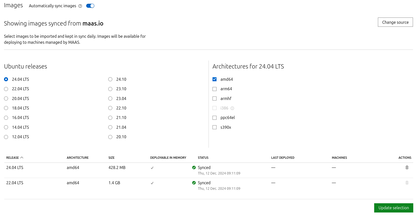
On the image selection page, select Ubuntu 24.04 LTS (amd64) and sync the image.
-
Import the previously generated SSH key (
id_rsa.pub) for thedepuserinto the MaaS admin user profile and finalize the setup.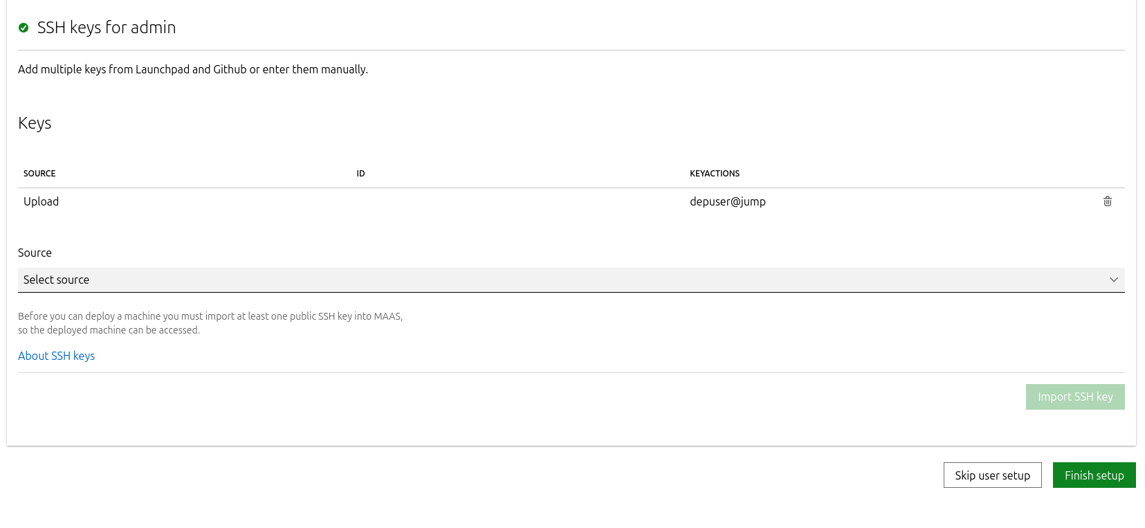
-
-
Update the DNS nameserver IP address in the Netplan files for both the Jump and MaaS VMs from
10.0.110.254to10.0.110.252, then reapply the configuration.
K8s Master VMs
Suggested specifications:
-
vCPU: 8
-
RAM: 16GB
-
Storage: 100GB
-
Network interface: Bridge device, connected to
mgmt-br
-
Before provisioning the Kubernetes (K8s) Master VMs with MaaS, create the required virtual disks with empty storage. Use the following one-liner to create three 100 GB QCOW2 virtual disks:
Hypervisor Console
$ for i in $(seq 1 3); do qemu-img create -f qcow2 /var/lib/libvirt/images/master$i.qcow2 100G; doneThis command generates the following disks in the
/var/lib/libvirt/images/directory:-
master1.qcow2 -
master2.qcow2 -
master3.qcow2
-
-
Configure VMs in virt-manager:
-
Open virt-manager and create three virtual machines:
-
Assign the corresponding virtual disk (
master1.qcow2,master2.qcow2, ormaster3.qcow2) to each VM. -
Configure each VM with the suggested specifications (vCPU, RAM, storage, and network interface).
-
-
During the VM setup, ensure the NIC is selected under the Boot Options tab. This ensures the VMs can PXE boot for MaaS provisioning.
-
Once the configuration is complete, shut down all the VMs.
-
-
After the VMs are created and configured, proceed to provision them via the MaaS interface. MaaS will handle the OS installation and further setup as part of the deployment process.
Provision Master VMs Using MaaS
Install virsh and Set Up SSH Access
-
SSH to the MaaS VM from the Jump node:
MaaS Console
depuser@jump:~$ ssh maas depuser@maas:~$ sudo -i -
Install the
virshclient to communicate with the hypervisor:MaaS Console
# apt install -y libvirt-clients -
Generate an SSH key for the
rootuser and copy it to the hypervisor user in thelibvirtdgroup:MaaS Console
# ssh-keygen -t rsa # ssh-copy-id ubuntu@<hypervisor_MGMT_IP> -
Verify SSH access and
virshcommunication with the hypervisor:MaaS Console
# virsh -c qemu+ssh://ubuntu@<hypervisor_MGMT_IP>/system list --allExpected output:
MaaS Console
Id Name State ------------------------------ 1 fw running 2 jump running 3 maas running - master1 shut off - master2 shut off - master3 shut off -
Copy the SSH key to the required MaaS directory (for snap-based installations):
MaaS Console
# mkdir -p /var/snap/maas/current/root/.ssh
# cp .ssh/id_rsa* /var/snap/maas/current/root/.ssh/
Get MAC Addresses of the Master VMs
Retrieve the MAC addresses of the Master VMs:
MaaS Console
# for i in $(seq 1 3); do virsh -c qemu+ssh://ubuntu@<hypervisor_MGMT_IP>/system dumpxml master$i | grep 'mac address'; done
Example output:
MaaS Console
<mac address='52:54:00:a9:9c:ef'/>
<mac address='52:54:00:19:6b:4d'/>
<mac address='52:54:00:68:39:7f'/>
Add Master VMs to MaaS
-
Add the Master VMs to MaaS:
Once added, MaaS will automatically start the newly added VMs commissioning (discovery and introspection).
MaaS Console
# maas admin machines create hostname=master1 architecture=amd64/generic mac_addresses='52:54:00:a9:9c:ef' power_type=virsh power_parameters_power_address=qemu+ssh://ubuntu@<hypervisor_MGMT_IP>/system power_parameters_power_id=master1 skip_bmc_config=1 testing_scripts=none
Success.
Machine-readable output follows:
{
    "description": "",
    "status_name": "Commissioning",
...
    "status": 1,
...
    "system_id": "c3seyq",
...
    "fqdn": "master1.dpf.rdg.local.domain",
    "power_type": "virsh",
...
    "status_message": "Commissioning",
    "resource_uri": "/MAAS/api/2.0/machines/c3seyq/"
}

# maas admin machines create hostname=master2 architecture=amd64/generic mac_addresses='52:54:00:19:6b:4d' power_type=virsh power_parameters_power_address=qemu+ssh://ubuntu@<hypervisor_MGMT_IP>/system power_parameters_power_id=master2 skip_bmc_config=1 testing_scripts=none

# maas admin machines create hostname=master3 architecture=amd64/generic mac_addresses='52:54:00:68:39:7f' power_type=virsh power_parameters_power_address=qemu+ssh://ubuntu@<hypervisor_MGMT_IP>/system power_parameters_power_id=master3 skip_bmc_config=1 testing_scripts=none
-
Repeat the command for
master2andmaster3with their respective MAC addresses. -
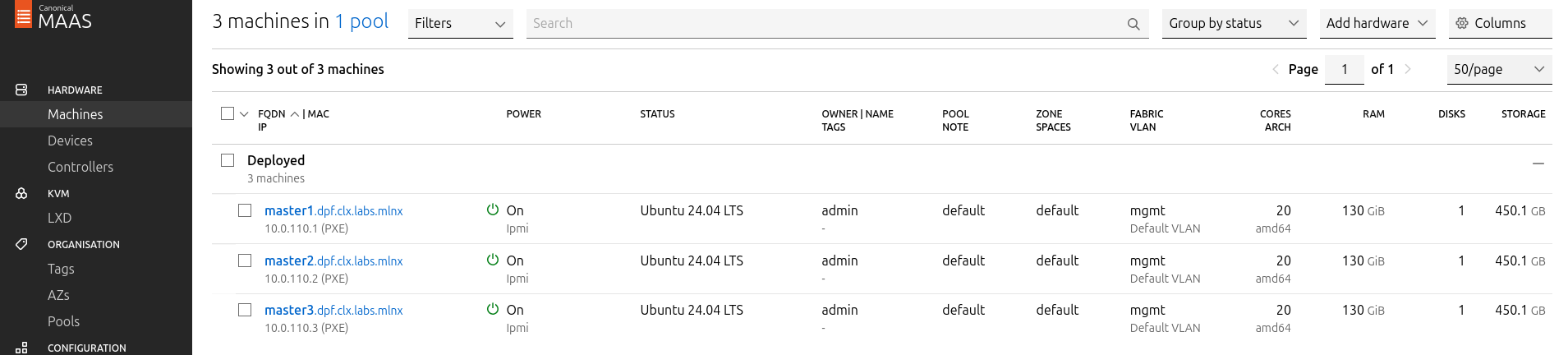
Verify commissioning by waiting for the status to change to "Ready" in MaaS.
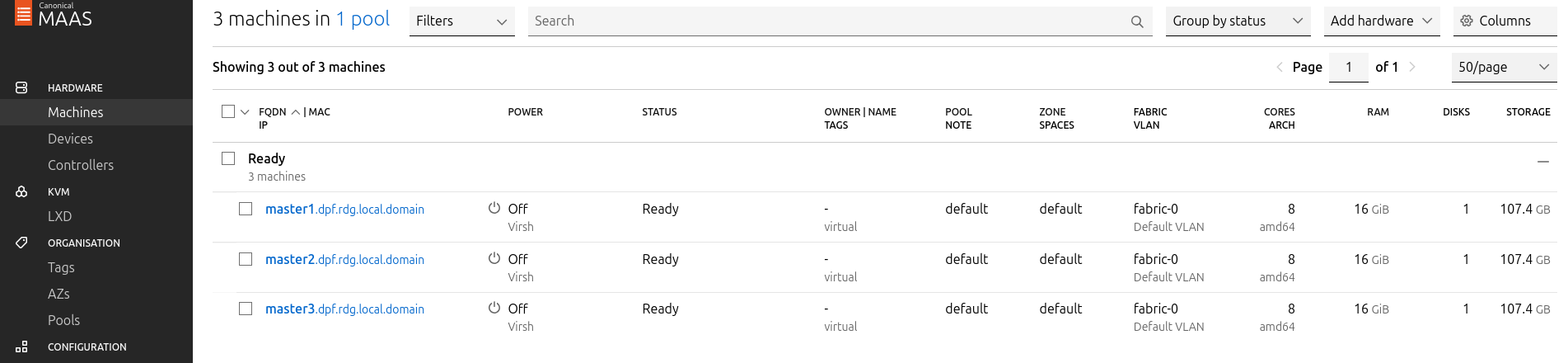
After commissioning, the next phase is deployment (OS provisioning).
Configure Master VMs Network
To ensure persistence across reboots, assign a static IP address to the management interface of the master nodes.
For each Master VM:
-
Navigate to Network and click "actions" near the management interface (a small arrowhead pointing down), then select "Edit Physical".
-
Configure as follows:
-
Subnet: 10.0.110.0/24
-
IP Mode: Static Assign
-
Address: Assign
10.0.110.1formaster1,10.0.110.2formaster2, and10.0.110.3formaster3.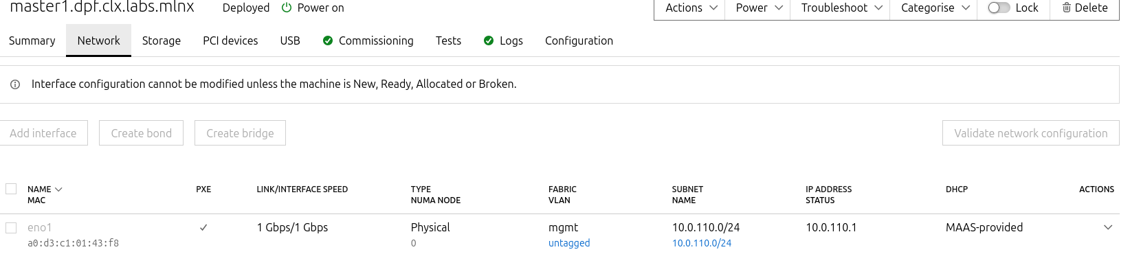
-
-
-
Save the interface settings for each VM.
Deploy Master VMs Using Cloud-Init
-
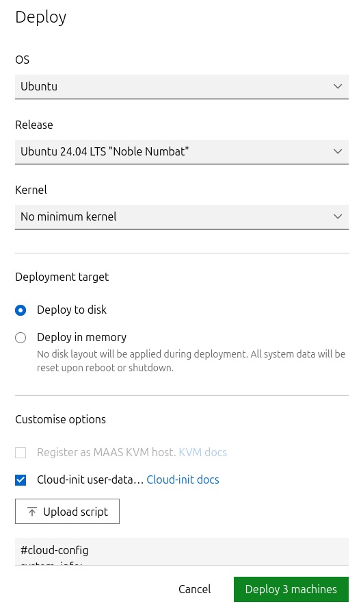
Use the following cloud-init script to configure the necessary software and ensure persistency:
Master nodes cloud-init
#cloud-config system_info: default_user: name: depuser passwd: "$6$jOKPZPHD9XbG72lJ$evCabLvy1GEZ5OR1Rrece3NhWpZ2CnS0E3fu5P1VcZgcRO37e4es9gmriyh14b8Jx8gmGwHAJxs3ZEjB0s0kn/" lock_passwd: false groups: [adm, audio, cdrom, dialout, dip, floppy, lxd, netdev, plugdev, sudo, video] sudo: ["ALL=(ALL) NOPASSWD:ALL"] shell: /bin/bash ssh_pwauth: True package_upgrade: true runcmd: - apt-get update - apt-get -y install nfs-common -
Deploy the master VMs:
-
Select all three Master VMs → Actions → Deploy.
-
Toggle Cloud-init user-data and paste the cloud-init script.
-
Start the deployment and wait for the status to change to "Ubuntu 24.04 LTS".
-
Verify Deployment
-
SSH into the Master VMs from the Jump node:
Jump Node Console
depuser@jump:~$ ssh master1 depuser@master1:~$ -
Run
sudowithout a password:Master1 Console
depuser@master1:~$ sudo -i root@master1:~# -
Verify installed packages:
Master1 Console
root@master1:~# apt list --installed | egrep 'nfs-common' nfs-common/noble,now 1:2.6.4-3ubuntu5 amd64 [installed] -
Reboot the Master VMs to complete the provisioning.
Master1 Console
root@master1:~# reboot
Repeat the verification commands for master2 and master3.
K8s Cluster Deployment and Configuration
Kubespray Deployment and Configuration
In this solution, the Kubernetes (K8s) cluster is deployed using a modified Kubespray (based on release v2.28.1) with a non-root depuser account from the Jump Node. The modifications in Kubespray are designed to meet the DPF prerequisites as described in the User Manual and facilitate cluster deployment and scaling.
-
Download the modified Kubespray archive: Unknown Attachment.
-
Extract the contents and navigate to the extracted directory:
Jump Node Console
$ tar -xzf /home/depuser/modified_kubespray_v2.28.1.tar.gz $ cd kubespray/ depuser@jump:~/kubespray$ -
Set the K8s API VIP address and DNS record. Replace it with your own IP address and DNS record if different:
Jump Node Console
depuser@jump:~/kubespray$ sed -i '/# kube_vip_address:/s/.*/kube_vip_address: 10.0.110.10/' inventory/mycluster/group_vars/k8s_cluster/addons.yml depuser@jump:~/kubespray$ sed -i '/apiserver_loadbalancer_domain_name:/s/.*/apiserver_loadbalancer_domain_name: "kube-vip.dpf.rdg.local.domain"/' roles/kubespray_defaults/defaults/main/main.yml -
Install the necessary dependencies and set up the Python virtual environment:
Jump Node Console
depuser@jump:~/kubespray$ sudo apt -y install python3-pip jq python3.12-venv depuser@jump:~/kubespray$ python3 -m venv .venv depuser@jump:~/kubespray$ source .venv/bin/activate (.venv) depuser@jump:~/kubespray$ python3 -m pip install --upgrade pip (.venv) depuser@jump:~/kubespray$ pip install -U -r requirements.txt (.venv) depuser@jump:~/kubespray$ pip install ruamel-yaml -
Verify that the
kube_network_pluginis set toflanneland thatkube_proxy_removeis set tofalsein theinventory/mycluster/group_vars/k8s_cluster/k8s-cluster.ymlfile.inventory/mycluster/group_vars/k8s_cluster/k8s-cluster.yml
[depuser@jump kubespray-2.28.0]$ vim inventory/mycluster/group_vars/k8s_cluster/k8s-cluster.yml ..... ## Change this to use another Kubernetes version, e.g. a current beta release kube_version: 1.32.8 ..... # Choose network plugin (cilium, calico, kube-ovn, weave or flannel. Use cni for generic cni plugin) # Can also be set to 'cloud', which lets the cloud provider setup appropriate routing kube_network_plugin: flannel .... # Kube-proxy proxyMode configuration. # Can be ipvs, iptables kube_proxy_remove: false kube_proxy_mode: ipvs ..... -
Review and edit the
inventory/mycluster/hosts.yamlfile to define the cluster nodes. The following is the configuration for this deployment:inventory/mycluster/hosts.yaml
YAMLall: hosts: master1: ansible_host: 10.0.110.1 ip: 10.0.110.1 access_ip: 10.0.110.1 node_labels: "k8s.ovn.org/zone-name": "master1" master2: ansible_host: 10.0.110.2 ip: 10.0.110.2 access_ip: 10.0.110.2 node_labels: "k8s.ovn.org/zone-name": "master2" master3: ansible_host: 10.0.110.3 ip: 10.0.110.3 access_ip: 10.0.110.3 node_labels: "k8s.ovn.org/zone-name": "master3" children: kube_control_plane: hosts: master1: master2: master3: kube_node: hosts: etcd: hosts: master1: master2: master3: k8s_cluster: children: kube_control_plane:
Deploying Cluster Using Kubespray Ansible Playbook
-
Run the following command from the Jump Node to initiate the deployment process:
Ensure you are in the Python virtual environment (
.venv) when running the command.
Jump Node Console
(.venv) depuser@jump:~/kubespray$ ansible-playbook -i inventory/mycluster/hosts.yaml --become --become-user=root cluster.yml -
It takes a while for this deployment to complete. Make sure there are no errors. Successful result example:
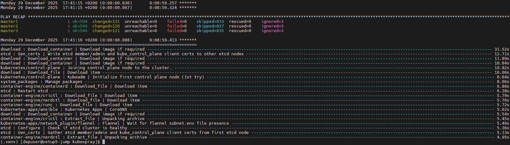
It is recommended to keep the shell from which Kubespray has been running open, later on it will be useful when performing cluster scale out to add the worker nodes.
K8s Deployment Verification
To simplify managing the K8s cluster from the Jump Host, set up kubectl with bash auto-completion.
-
Copy
kubectland the kubeconfig file frommaster1to the Jump Host:Jump Node Console
## Connect to master1 depuser@jump:~$ ssh master1 depuser@master1:~$ cp /usr/local/bin/kubectl /tmp/ depuser@master1:~$ sudo cp /root/.kube/config /tmp/kube-config depuser@master1:~$ sudo chmod 644 /tmp/kube-config -
In another terminal tab, copy the files to the Jump Host:
Jump Node Console
depuser@jump:~$ scp master1:/tmp/kubectl /tmp/ depuser@jump:~$ sudo chown root:root /tmp/kubectl depuser@jump:~$ sudo mv /tmp/kubectl /usr/local/bin/ depuser@jump:~$ mkdir -p ~/.kube depuser@jump:~$ scp master1:/tmp/kube-config ~/.kube/config depuser@jump:~$ chmod 600 ~/.kube/config -
Enable bash auto-completion for
kubectl:-
Verify if bash-completion is installed:
Jump Node Console
depuser@jump:~$ type _init_completionIf installed, the output includes:
Jump Node Console
_init_completion is a function -
If not installed, install it:
Jump Node Console
depuser@jump:~$ sudo apt install -y bash-completion -
Set up the
kubectlcompletion script:Jump Node Console
depuser@jump:~$ kubectl completion bash | sudo tee /etc/bash_completion.d/kubectl > /dev/null
depuser@jump:~$ bash
-
-
Check the status of the nodes in the cluster:
Jump Node Console
depuser@jump:~$ kubectl get nodesExpected output:
Jump Node Console
NAME STATUS ROLES AGE VERSION master1 Ready control-plane 3m59s v1.32.8 master2 Ready control-plane 3m51s v1.32.8 master3 Ready control-plane 3m48s v1.32.8 -
Check the pods in all namespaces:
Jump Node Console
depuser@jump:~$ kubectl get pods -AExpected output:
Jump Node Console
[depuser@setup5-jump ~]$ kubectl get pods -A
NAMESPACE     NAME                              READY   STATUS    RESTARTS   AGE
kube-system   coredns-5c54f84c97-7245f          1/1     Running   0          3m41s
kube-system   coredns-5c54f84c97-gk4pb          1/1     Running   0          3m38s
kube-system   dns-autoscaler-56cb45595c-bv28g   1/1     Running   0          3m40s
kube-system   kube-apiserver-master1            1/1     Running   0          4m43s
kube-system   kube-apiserver-master2            1/1     Running   0          4m34s
kube-system   kube-apiserver-master3            1/1     Running   0          4m32s
kube-system   kube-controller-manager-master1   1/1     Running   1          4m43s
kube-system   kube-controller-manager-master2   1/1     Running   2          4m34s
kube-system   kube-controller-manager-master3   1/1     Running   1          4m32s
kube-system   kube-flannel-cptzm                1/1     Running   0          3m54s
kube-system   kube-flannel-m2gw4                1/1     Running   0          3m54s
kube-system   kube-flannel-ql46d                1/1     Running   0          3m54s
kube-system   kube-proxy-62dwr                  1/1     Running   0          4m35s
kube-system   kube-proxy-dc4sb                  1/1     Running   0          4m39s
kube-system   kube-proxy-mhbtb                  1/1     Running   0          4m32s
kube-system   kube-scheduler-master1            1/1     Running   1          4m43s
kube-system   kube-scheduler-master2            1/1     Running   1          4m34s
kube-system   kube-scheduler-master3            1/1     Running   1          4m32s
kube-system   kube-vip-master1                  1/1     Running   0          4m43s
kube-system   kube-vip-master2                  1/1     Running   0          4m34s
kube-system   kube-vip-master3                  1/1     Running   0          4m32s
DPF Installation
Software Prerequisites and Required Variables
-
Start by installing the remaining software perquisites.
Jump Node Console
## Connect to master1 to copy helm client utility that was installed during kubespray deployment $ depuser@jump:~$ ssh master1 depuser@master1:~$ cp /usr/local/bin/helm /tmp/ ## In another tab depuser@jump:~$ scp master1:/tmp/helm /tmp/ depuser@jump:~$ sudo chown root:root /tmp/helm depuser@jump:~$ sudo mv /tmp/helm /usr/local/bin/ ## Verify that envsubst utility is installed depuser@jump:~$ which envsubst /usr/bin/envsubst -
Proceed to clone the doca-platform Git repository:
Jump Node Console
$ git clone https://github.com/NVIDIA/doca-platform.git -
Change directory to doca-platform and checkout to tag v26.4.0:
Jump Node Console
$ cd doca-platform/ $ git checkout v26.4.0 -
Change directory to readme.md from where all the commands will be run:
Jump Node Console
$ cd docs/public/user-guides/zero-trust/use-cases/passthrough/ -
Change the BMC root's password.
In Zero Trust mode, provisioning DPUs requires authentication with Redfish.
In order to do that, you must set the same root password to access the BMC for all DPUs DPF is going to manage.For more information on how to set the BMC root password refer to BlueField DPU Administrator Quick Start Guide.Connect to the first DPU BMC over SSH to change the BMC root's password:
Jump Node Console
$ ssh root@10.0.110.201 root@10.0.110.201's password: <BMC Root Password. Default root/0penBmc. need to change first time to $BMC_ROOT_PASSWORD in the manifests/00-env-vars/envvars.env file> -
Modify the variables in
manifests/00-env-vars/envvars.envto fit your environment, then source the file:Replace the values for the variables in the following file with the values that fit your setup. Specifically, pay attention to
DPUCLUSTER_INTERFACE,BMC_ROOT_PASSWORD, andDPU's serial number.
To get aDPU's serial numberyou can use following command. Sample:
$ curl -k -u root:'BMC root password' https://10.0.110.201/redfish/v1/Systems/Bluefield | jq -r '.SerialNumber | ascii_downcase'
% Total % Received % Xferd Average Speed Time Time Time Current
Dload Upload Total Spent Left Speed
100 4970 100 4970 0 0 4211 0 0:00:01 0:00:01 --:--:-- 4211
mt2402xz0f7xmanifests/00-env-vars/envvars.env
Bash## IP Address for the Kubernetes API server of the target cluster on which DPF is installed. ## This should never include a scheme or a port. ## e.g. 10.10.10.10 export TARGETCLUSTER_API_SERVER_HOST=10.0.110.10 ## Port for the Kubernetes API server of the target cluster on which DPF is installed. ## e.g. 6443 export TARGETCLUSTER_API_SERVER_PORT=6443 ## Virtual IP used by the load balancer for the DPU Cluster. Must be a reserved IP from the management subnet and not ## allocated by DHCP. export DPUCLUSTER_VIP=10.0.110.200 ## Interface on which the DPUCluster load balancer will listen. Should be the management interface of the control plane node. export DPUCLUSTER_INTERFACE=ens160 ## IP address to the NFS server used as storage for the BFB. export NFS_SERVER_IP=10.0.110.253 ## The DPF REGISTRY is the Helm repository URL where the DPF Operator Chart resides. ## Usually this is the NVIDIA Helm NGC registry. For development purposes, this can be set to a different repository. export REGISTRY=https://helm.ngc.nvidia.com/nvidia/doca ## The DPF TAG is the version of the DPF components which will be deployed in this guide. export TAG=v26.4.0 ## URL to the BFB used in the `bfb.yaml` and linked by the DPUSet. export BFB_URL="https://nbu-nfs.gtm.nvidia.com/auto/sw_mc_soc_release/doca_dpu/doca_3.4.0/20260428/bfbs/pk/bf-bundle-3.4.0-73_26.04_ubuntu-24.04_64k_prod.bfb" ## IP_RANGE_START and IP_RANGE_END ## These define the IP range for DPU discovery via Redfish/BMC interfaces ## Example: If your DPUs have BMC IPs in range 10.0.110.201-240 ## export IP_RANGE_START=10.0.110.201 ## export IP_RANGE_END=10.0.110.204 ## Start of DPUDiscovery IpRange export IP_RANGE_START=10.0.110.201 ## End of DPUDiscovery IpRange export IP_RANGE_END=10.0.110.204 # The password used for DPU BMC root login, must be the same for all DPUs # For more information on how to set the BMC root password refer to BlueField DPU Administrator Quick Start Guide. export BMC_ROOT_PASSWORD=<set your BMC_ROOT_PASSWORD> -
Export environment variables for the installation:
Jump Node Console
$ source manifests/00-env-vars/envvars.env
DPF Operator Installation
Verify the rshim service
Verify that the rshim service is runnging.
-
Connect to the first DPU BMC over SSH:
Jump Node Console
$ ssh root@10.0.110.201 -
Verify that the
rshimservice is runnging or run if not.Jump Node Console
root@dpu-bmc:~# systemctl status rshim * rshim.service - rshim driver for BlueField SoC Loaded: loaded (/usr/lib/systemd/system/rshim.service; enabled; preset: disabled) Active: active (running) since Mon 2025-07-14 13:21:34 UTC; 18h ago Docs: man:rshim(8) Process: 866 ExecStart=/usr/sbin/rshim $OPTIONS (code=exited, status=0/SUCCESS) Main PID: 874 (rshim) CPU: 2h 43min 44.730s CGroup: /system.slice/rshim.service `-874 /usr/sbin/rshim Jul 14 13:21:34 dpu-bmc (rshim)[866]: rshim.service: Referenced but unset environment variable evaluates to an empty string: OPTIONS Jul 14 13:21:34 dpu-bmc rshim[874]: Created PID file: /var/run/rshim.pid Jul 14 13:21:34 dpu-bmc rshim[874]: USB device detected Jul 14 13:21:38 dpu-bmc rshim[874]: Probing usb-2.1 Jul 14 13:21:38 dpu-bmc rshim[874]: create rshim usb-2.1 Jul 14 13:21:39 dpu-bmc rshim[874]: rshim0 attached root@dpu-bmc:~# ls /dev/rshim0 boot console misc rshim # To start the rshim, if not runnging root@dpu-bmc:~# systemctl enable rshim root@dpu-bmc:~# systemctl start rshim root@dpu-bmc:~# systemctl status rshim root@dpu-bmc:~# ls /dev/rshim0 root@dpu-bmc:~# exit $ curl -k -u root:'set your BMC_ROOT_PASSWORD' https://10.0.110.201/redfish/v1/Systems/Bluefield -
Repeat the step 1-2 on all your DPUs.
The password is provided to DPF by creating the following secret:
It is necessary to set several environment variables before running this command.
$ source manifests/00-env-vars/envvars.env
Jump Node Console
$ kubectl create secret generic -n dpf-operator-system bmc-shared-password --from-literal=password=$BMC_ROOT_PASSWORD
Additional Dependencies
The DPF Operator requires several prerequisite components to function properly in a Kubernetes environment. Starting with DPF v25.7, all Helm dependencies have been removed from the DPF chart. This means that all dependencies must be installed manually before installing the DPF chart itself. The following commands describe an opiniated approach to install those dependencies (for more information, check: Helm Prerequisites - NVIDIA Docs).
-
Create the NS for the operator:
Jump Node Console
$ kubectl create ns dpf-operator-system -
Install Go 1.25:
Jump Node Console
$ wget https://go.dev/dl/go1.25.8.linux-amd64.tar.gz $ sudo rm -rf /usr/local/go && sudo tar -C /usr/local -xzf go1.25.8.linux-amd64.tar.gz $ echo 'export PATH=$PATH:/usr/local/go/bin' >> ~/.bashrc && source ~/.bashrc -
Install
helmfilebinary:Jump Node Console
$ wget https://github.com/helmfile/helmfile/releases/download/v1.1.2/helmfile_1.1.2_linux_amd64.tar.gz $ tar -xvf helmfile_1.1.2_linux_amd64.tar.gz $ sudo mv ./helmfile /usr/local/bin/ -
Change directory to doca-platform:
Use another shell from the one where you run all the other installation commands for DPF.
Jump Node Console
$ cd /home/depuser/doca-platform -
Install Helm dependencies using the following command:
Jump Node Console
$ make HELMFILE_FILE=deploy/helmfiles/prereqs.yaml test-deploy-helmfile
.....
UPDATED RELEASES:
NAME                     NAMESPACE                CHART                                               VERSION   DURATION
node-feature-discovery   dpf-operator-system      node-feature-discovery/node-feature-discovery       0.18.3         14s
local-path-provisioner   local-path-provisioner   local-storage/local-path-provisioner                0.0.34         20s
cert-manager             cert-manager             jetstack/cert-manager                               v1.19.3        24s
argo-cd                  dpf-operator-system      argoproj/argo-cd                                    9.4.1          39s
maintenance-operator     dpf-operator-system      oci://ghcr.io/mellanox/maintenance-operator-chart   0.2.3          25s
kamaji                   dpf-operator-system      oci://ghcr.io/nvidia/charts/kamaji                  1.2.0        8m49s
DPF Operator Deployment
-
Run the following commands to substitute the environment variables and install the DPF Operator:
Jump Node Console
$ helm repo add --force-update dpf-repository ${REGISTRY} $ helm repo update $ helm upgrade --install -n dpf-operator-system dpf-operator dpf-repository/dpf-operator --version=$TAG Release "dpf-operator" does not exist. Installing it now. I1231 10:01:11.907400 2304105 warnings.go:110] "Warning: spec.template.spec.affinity.nodeAffinity.requiredDuringSchedulingIgnoredDuringExecution.nodeSelectorTerms[0].matchExpressions[0].key: node-role.kubernetes.io/master is use \"node-role.kubernetes.io/control-plane\" instead" I1231 10:01:11.919779 2304105 warnings.go:110] "Warning: spec.jobTemplate.spec.template.spec.affinity.nodeAffinity.requiredDuringSchedulingIgnoredDuringExecution.nodeSelectorTerms[0].matchExpressions[0].key: node-role.kubernetes.io/master is use \"node-role.kubernetes.io/control-plane\" instead" NAME: dpf-operator LAST DEPLOYED: Wed Dec 31 10:01:10 2025 NAMESPACE: dpf-operator-system STATUS: deployed REVISION: 1 TEST SUITE: None -
Verify the DPF Operator installation by ensuring the deployment is available and all the pods are ready:
The following verification commands may need to be run multiple times to ensure the conditions are met.
Jump Node Console
## Ensure the DPF Operator deployment is available.
$ kubectl rollout status deployment --namespace dpf-operator-system dpf-operator-controller-manager
deployment "dpf-operator-controller-manager" successfully rolled out

## Ensure all pods in the DPF Operator system are ready.
$ kubectl wait --for=condition=ready --namespace dpf-operator-system pods --all
pod/argo-cd-argocd-application-controller-0 condition met
pod/argo-cd-argocd-redis-77dfd8fcb4-nq545 condition met
pod/argo-cd-argocd-repo-server-7b6c5b8cdb-mct95 condition met
pod/argo-cd-argocd-server-744d5f9c7c-4knwj condition met
pod/dpf-operator-controller-manager-645467745b-gqqsg condition met
pod/kamaji-556cb86895-99lsh condition met
pod/kamaji-etcd-0 condition met
pod/kamaji-etcd-1 condition met
pod/kamaji-etcd-2 condition met
pod/maintenance-operator-585767f779-qrfvg condition met
pod/node-feature-discovery-gc-7f64f764f8-gvdgh condition met
pod/node-feature-discovery-master-6fbc95665c-4njbd condition met
DPF System Installation
This section involves creating the DPF system components and some basic infrastructure required for a functioning DPF-enabled cluster.
-
Change directory back to:
Jump Node Console
$ cd /home/depuser/doca-platform/docs/public/user-guides/zero-trust/use-cases/passthrough/ -
The following YAML files define the DPFOperatorConfig to install the DPF System components, the DPUCluster to serve as the Kubernetes control plane for DPU nodes, and DPUDiscovery to discover DPUDevices and DPUNodes.
---
apiVersion: provisioning.dpu.nvidia.com/v1alpha1
kind: DPUCluster
metadata:
  name: dpu-cplane-tenant1
  namespace: dpu-cplane-tenant1
spec:
  type: kamaji
  maxNodes: 1000
  clusterEndpoint:
    # deploy keepalived instances on the nodes that match the given nodeSelector.
    keepalived:
      # interface on which keepalived will listen. Should be the oob interface of the control plane node.
      interface: $DPUCLUSTER_INTERFACE
      # Virtual IP reserved for the DPU Cluster load balancer. Must not be allocatable by DHCP.
      vip: $DPUCLUSTER_VIP
      # virtualRouterID must be in range [1,255], make sure the given virtualRouterID does not duplicate with any existing keepalived process running on the host
      virtualRouterID: 126
      nodeSelector:
        node-role.kubernetes.io/control-plane: ""
---
apiVersion: provisioning.dpu.nvidia.com/v1alpha1
kind: DPUDiscovery
metadata:
  name: dpu-discovery
  namespace: dpf-operator-system
spec:
  # Define the IP range to scan
  ipRangeSpec:
    ipRange:
      startIP: $IP_RANGE_START
      endIP:   $IP_RANGE_END
-
Create NS for the Kubernetes control plane of the DPU nodes:
Jump Node Console
$ kubectl create ns dpu-cplane-tenant1 -
Apply the previous YAML files:
Jump Node Console
$ cat manifests/02-dpf-system-installation/*.yaml | envsubst | kubectl apply -f -
-
Verify the DPF system by ensuring that the provisioning and DPUService controller manager deployments are available, that all other deployments in the DPF Operator system are available, and that the DPUCluster is ready for nodes to join.
Jump Node Console
## Ensure the provisioning and DPUService controller manager deployments are available.
$ kubectl rollout status deployment --namespace dpf-operator-system dpf-provisioning-controller-manager dpuservice-controller-manager

deployment "dpf-provisioning-controller-manager" successfully rolled out
deployment "dpuservice-controller-manager" successfully rolled out

## Ensure all other deployments in the DPF Operator system are Available.
$ kubectl rollout status deployment --namespace dpf-operator-system

deployment "argo-cd-argocd-applicationset-controller" successfully rolled out
deployment "argo-cd-argocd-redis" successfully rolled out
deployment "argo-cd-argocd-repo-server" successfully rolled out
deployment "argo-cd-argocd-server" successfully rolled out
deployment "dpf-operator-controller-manager" successfully rolled out
deployment "dpf-provisioning-controller-manager" successfully rolled out
deployment "dpuservice-controller-manager" successfully rolled out
deployment "kamaji" successfully rolled out
deployment "kamaji-cm-controller-manager" successfully rolled out
deployment "maintenance-operator" successfully rolled out
deployment "node-feature-discovery-gc" successfully rolled out
deployment "node-feature-discovery-master" successfully rolled out
deployment "servicechainset-controller-manager" successfully rolled out

## Ensure bfb registry daemonset is available
$ kubectl get pod -n dpf-operator-system bfb-registry

## The pod must be in `Running/Ready` state before DPU provisioning starts.

## Ensure the DPUCluster is ready for nodes to join.(Take time)
$ kubectl wait --for=condition=ready --namespace dpu-cplane-tenant1 dpucluster --all

dpucluster.provisioning.dpu.nvidia.com/dpu-cplane-tenant1 condition met


$ kubectl get dpudiscoveries.provisioning.dpu.nvidia.com -A
NAMESPACE             NAME            LAST SCAN   FOUND DPUS
dpf-operator-system   dpu-discovery   92s         4
-
Verify the DPF system by ensuring that the
DPUDevicesexist:Jump Node Console
$ kubectl get dpudevices -n dpf-operator-system NAME READY mt2402xz0f7x mt2402xz0f80 mt2402xz0f8g mt2402xz0f9n -
Verify the DPF system by ensuring that the
DPUNodesexist.Jump Node Console
$ kubectl get dpunodes -n dpf-operator-system
NAME                    AGE
dpu-node-mt2402xz0f7x   3m17s
dpu-node-mt2402xz0f80   3m16s
dpu-node-mt2402xz0f8g   3m15s
dpu-node-mt2402xz0f9n   3m15s
Congratulations, the DPF system has been successfully installed!
(Optional) DPF system installation verification
For the verification phase, our focus is on provisioning NVIDIA® BlueField®-3 DPUs through DPF and configuring them to operate in passthrough mode.
-
Export environment variables for the installation:
Jump Node Console
$ source manifests/00-env-vars/envvars.env -
Use the following YAMLs to define a
BFBresource, aDPUFlavor, aDPUSet, aDPUServiceInterfaces, and aDPUServiceChain:--- apiVersion: provisioning.dpu.nvidia.com/v1alpha1 kind: BFB metadata: name: bf-bundle-$TAG namespace: dpf-operator-system spec: url: $BFB_URL--- apiVersion: provisioning.dpu.nvidia.com/v1alpha1 kind: DPUFlavor metadata: name: passthrough-$TAG namespace: dpf-operator-system spec: dpuMode: zero-trust grub: kernelParameters: - console=hvc0 - console=ttyAMA0 - earlycon=pl011,0x13010000 - fixrttc - net.ifnames=0 - biosdevname=0 - iommu.passthrough=1 - cgroup_no_v1=net_prio,net_cls - hugepagesz=2048kB - hugepages=3072 nvconfig: - device: "*" parameters: - PF_BAR2_ENABLE=0 - PER_PF_NUM_SF=1 - PF_TOTAL_SF=20 - PF_SF_BAR_SIZE=10 - NUM_PF_MSIX_VALID=0 - PF_NUM_PF_MSIX_VALID=1 - PF_NUM_PF_MSIX=228 - INTERNAL_CPU_MODEL=1 - INTERNAL_CPU_OFFLOAD_ENGINE=0 - SRIOV_EN=1 - NUM_OF_VFS=46 - LAG_RESOURCE_ALLOCATION=1 - LINK_TYPE_P1=ETH - LINK_TYPE_P2=ETH - EXP_ROM_UEFI_x86_ENABLE=1 ovs: rawConfigScript: | _ovs-vsctl() { ovs-vsctl --no-wait --timeout 15 "$@" } _ovs-vsctl set Open_vSwitch . other_config:doca-init=true _ovs-vsctl set Open_vSwitch . other_config:dpdk-max-memzones=50000 _ovs-vsctl set Open_vSwitch . other_config:hw-offload=true _ovs-vsctl set Open_vSwitch . other_config:pmd-quiet-idle=true _ovs-vsctl set Open_vSwitch . other_config:max-idle=20000 _ovs-vsctl set Open_vSwitch . other_config:max-revalidator=5000 _ovs-vsctl set Open_vSwitch . other_config:doca-congestion-threshold=60 _ovs-vsctl set Open_vSwitch . other_config:flow-limit=500000 _ovs-vsctl set Open_vSwitch . other_config:hw-offload-ct-unidir-udp-enabled=true _ovs-vsctl --if-exists del-br ovsbr1 _ovs-vsctl --if-exists del-br ovsbr2 if systemctl list-unit-files openvswitch-switch.service &>/dev/null; then systemctl restart openvswitch-switch elif systemctl list-unit-files openvswitch.service &>/dev/null; then systemctl restart openvswitch fi _ovs-vsctl --may-exist add-br br-sfc _ovs-vsctl set bridge br-sfc datapath_type=netdev _ovs-vsctl set bridge br-sfc fail_mode=secure _ovs-vsctl --may-exist add-port br-sfc p0 _ovs-vsctl set Interface p0 type=dpdk _ovs-vsctl set Interface p0 mtu_request=9216 _ovs-vsctl set Port p0 external_ids:dpf-type=physical bfcfgParameters: - UPDATE_ATF_UEFI=yes - UPDATE_DPU_OS=yes - WITH_NIC_FW_UPDATE=yes configFiles: - path: /etc/mellanox/mlnx-bf.conf operation: override raw: | ALLOW_SHARED_RQ="no" IPSEC_FULL_OFFLOAD="no" ENABLE_ESWITCH_MULTIPORT="yes" permissions: "0644" - path: /etc/mellanox/mlnx-ovs.conf operation: override raw: | CREATE_OVS_BRIDGES="no" OVS_DOCA="yes" permissions: "0644" - path: /etc/mellanox/mlnx-sf.conf operation: override raw: "" permissions: "0644"
---
apiVersion: provisioning.dpu.nvidia.com/v1alpha1
kind: DPUSet
metadata:
  name: passthrough
  namespace: dpf-operator-system
spec:
  strategy:
    type: OnDelete
  dpuNodeSelector:
    matchLabels:
      feature.node.kubernetes.io/dpu-enabled: "true"
  dpuTemplate:
    spec:
      dpuFlavor: passthrough-$TAG
      bfb:
        name: bf-bundle-$TAG
      nodeEffect:
        hold: true
Please notice that with default nodeEffect above, DPU provisioning workflow will be paused and wait for an external signal (annotation) in order to proceed, as demonstrated in upcoming steps.
To implement a fully automated process that won’t require user intervention, see customAction option.
---
apiVersion: svc.dpu.nvidia.com/v1alpha1
kind: DPUServiceInterface
metadata:
  name: p0
  namespace: dpf-operator-system
spec:
  template:
    spec:
      template:
        metadata:
          labels:
            interface: "p0"
        spec:
          interfaceType: physical
          physical:
            interfaceName: p0
---
apiVersion: svc.dpu.nvidia.com/v1alpha1
kind: DPUServiceInterface
metadata:
  name: p1
  namespace: dpf-operator-system
spec:
  template:
    spec:
      template:
        metadata:
          labels:
            interface: "p1"
        spec:
          interfaceType: physical
          physical:
            interfaceName: p1
---
apiVersion: svc.dpu.nvidia.com/v1alpha1
kind: DPUServiceInterface
metadata:
  name: pf0hpf
  namespace: dpf-operator-system
spec:
  template:
    spec:
      template:
        metadata:
          labels:
            interface: "pf0hpf"
        spec:
          interfaceType: pf
          pf:
            pfID: 0
---
apiVersion: svc.dpu.nvidia.com/v1alpha1
kind: DPUServiceInterface
metadata:
  name: pf1hpf
  namespace: dpf-operator-system
spec:
  template:
    spec:
      template:
        metadata:
          labels:
            interface: "pf1hpf"
        spec:
          interfaceType: pf
          pf:
            pfID: 1
--- apiVersion: svc.dpu.nvidia.com/v1alpha1 kind: DPUServiceChain metadata: name: passthrough namespace: dpf-operator-system spec: template: spec: template: spec: switches: - ports: - serviceInterface: matchLabels: interface: p0 - serviceInterface: matchLabels: interface: pf0hpf - ports: - serviceInterface: matchLabels: interface: p1 - serviceInterface: matchLabels: interface: pf1hpf -
Run the command;
Jump Node Console
$ cat manifests/03-dpf-object-installation/*.yaml | envsubst |kubectl apply -f -This will deploy the following objects:
-
BFB to download the BFB to a shared volume
-
DPUFlavor used for provisioning the DPUs
-
DPUSet to provision DPUs on worker nodes
-
DPUServiceInterfaces used by the DPUServiceChain
-
-
To follow the progress of DPU provisioning, run the following command to check its current phase:Jump Node Console
$ watch -n10 "kubectl describe dpu -n dpf-operator-system | grep 'Node Name\|Type\|Last\|Phase'"
-
Wait for the NodeEffect stage (at this point the provisioning is paused, waintig for external signal).
Run following command on all/specific DPU nodemaintanace object/s to proceed with provisioning:Jump Node Console
$ kubectl annotate dpunodemaintenances -n dpf-operator-system --all provisioning.dpu.nvidia.com/wait-for-external-nodeeffect=false --overwrite -
To follow the progress of DPU provisioning, run the following command to check its current phase:Jump Node Console
$ watch -n10 "kubectl describe dpu -n dpf-operator-system | grep 'Node Name\|Type\|Last\|Phase'"
Every 10.0s: kubectl describe dpu -n dpf-operator-system | grep 'Node Name\|Type\|Last\|Phase'                                                                           setup5-jump: Mon Dec 29 21:33:38 2025

  Dpu Node Name:                            dpu-node-mt2402xz0f7x
    Last Transition Time:  2025-12-29T17:48:17Z
    Type:                  BFBPrepared
    Last Transition Time:  2025-12-29T17:48:13Z
    Type:                  BFBReady
    Last Transition Time:  2025-12-29T17:52:56Z
    Type:                  BFBTransferred
    Last Transition Time:  2025-12-29T17:48:16Z
    Type:                  FWConfigured
    Last Transition Time:  2025-12-29T17:47:28Z
    Type:                  Initialized
    Last Transition Time:  2025-12-29T17:48:14Z
    Type:                  InterfaceInitialized
    Last Transition Time:  2025-12-29T17:48:13Z
    Type:                  NodeEffectReady
    Last Transition Time:  2025-12-29T18:31:22Z
    Reason:                OemLastState
    Type:                  OSInstalled
    Last Transition Time:  2025-12-29T18:34:23Z
    Type:                  Rebooted
  Phase:                Rebooting
  Dpu Node Name:                            dpu-node-mt2402xz0f80
    Last Transition Time:  2025-12-29T17:48:18Z
    Type:                  BFBPrepared
    Last Transition Time:  2025-12-29T17:48:13Z
    Type:                  BFBReady
    Last Transition Time:  2025-12-29T17:52:56Z
    Type:                  BFBTransferred
    Last Transition Time:  2025-12-29T17:48:16Z
    Type:                  FWConfigured
    Last Transition Time:  2025-12-29T17:47:28Z
    Type:                  Initialized
    Last Transition Time:  2025-12-29T17:48:15Z
    Type:                  InterfaceInitialized
    Last Transition Time:  2025-12-29T17:48:14Z
    Type:                  NodeEffectReady
    Last Transition Time:  2025-12-29T18:30:22Z
    Reason:                OemLastState
    Type:                  OSInstalled
    Last Transition Time:  2025-12-29T18:33:29Z
    Type:                  Rebooted
  Phase:                Rebooting

.....
or with dpfctl:Jump Node Console
$ kubectl -n dpf-operator-system exec deploy/dpf-operator-controller-manager -- /dpfctl describe dpusets NAME NAMESPACE STATUS REASON SINCE MESSAGE DPFOperatorConfig/dpfoperatorconfig dpf-operator-system │ ├─Ready False Pending 114m The following conditions are not ready: │ │ * SystemComponentsReady │ └─SystemComponentsReady False Error 106m System components must be ready for DPFOperatorConfig to become Ready: │ * nvidia-k8s-ipam: DPUService dpf-operator-system/nvidia-k8s-ipam is not ready ├─DPUServiceChains │ └─DPUServiceChain/passthrough dpf-operator-system Ready: True Success 106m ├─DPUServiceInterfaces │ └─4 DPUServiceInterfaces... dpf-operator-system Ready: True Success 106m See p0, p1, pf0hpf, pf1hpf ├─DPUServiceNADs │ └─DPUServiceNAD/mybrsfc dpf-operator-system Ready: True Success 112m └─DPUSets └─DPUSet/passthrough dpf-operator-system │ └─Ready False Pending 106m Some DPUs are not ready ├─BFB/bf-bundle-v25.10.0 dpf-operator-system Ready: True Ready 106m File: bf-bundle-3.2.1-34_25.11_ubuntu-24.04_64k_prod.bfb, DOCA: 3.2.1 ├─DPUNodes │ ├─DPUNode/dpu-node-mt2402xz0f7x dpf-operator-system │ │ │ └─Ready False Ready 59m DPU dpu-node-mt2402xz0f7x-mt2402xz0f7x is in Rebooting phase │ │ └─DPUDevices │ │ └─DPUDevice/mt2402xz0f7x dpf-operator-system Ready: True Success 114m │ ├─DPUNode/dpu-node-mt2402xz0f80 dpf-operator-system │ │ │ └─Ready False Ready 60m DPU dpu-node-mt2402xz0f80-mt2402xz0f80 is in Rebooting phase │ │ └─DPUDevices │ │ └─DPUDevice/mt2402xz0f80 dpf-operator-system Ready: True Success 114m │ ├─DPUNode/dpu-node-mt2402xz0f8g dpf-operator-system │ │ │ └─Ready False Ready 59m DPU dpu-node-mt2402xz0f8g-mt2402xz0f8g is in Rebooting phase │ │ └─DPUDevices │ │ └─DPUDevice/mt2402xz0f8g dpf-operator-system Ready: True Success 113m │ └─DPUNode/dpu-node-mt2402xz0f9n dpf-operator-system │ │ └─Ready False Ready 57m DPU dpu-node-mt2402xz0f9n-mt2402xz0f9n is in Rebooting phase │ └─DPUDevices │ └─DPUDevice/mt2402xz0f9n dpf-operator-system Ready: True Success 114m └─DPUs ├─DPU/dpu-node-mt2402xz0f7x-mt2402xz0f7x dpf-operator-system │ ├─Rebooted False WaitingForManualPowerCycleOrReboot 59m │ └─Ready False Rebooting 59m ├─DPU/dpu-node-mt2402xz0f80-mt2402xz0f80 dpf-operator-system │ ├─Rebooted False WaitingForManualPowerCycleOrReboot 60m │ └─Ready False Rebooting 60m ├─DPU/dpu-node-mt2402xz0f8g-mt2402xz0f8g dpf-operator-system │ ├─Rebooted False WaitingForManualPowerCycleOrReboot 59m │ └─Ready False Rebooting 59m └─DPU/dpu-node-mt2402xz0f9n-mt2402xz0f9n dpf-operator-system ├─Rebooted False WaitingForManualPowerCycleOrReboot 57m └─Ready False Rebooting 57m -
Wait for the Rebooted stage and then Power Cycle the bare-metal host manual.
After the DPU is up, run following command for all/each DPU worker:Jump Node Console
$ kubectl annotate dpunodes -n dpf-operator-system --all provisioning.dpu.nvidia.com/dpunode-external-reboot-required- -
At this point, the DPU workers should be added to the cluster. As they being added to the cluster, the DPUs are provisioned.
Jump Node Console
$ watch -n10 "kubectl describe dpu -n dpf-operator-system | grep 'Node Name\|Type\|Last\|Phase'" Every 10.0s: kubectl describe dpu -n dpf-operator-system | grep 'Node Name\|Type\|Last\|Phase' setup5-jump: Mon Dec 29 21:41:37 2025 Dpu Node Name: dpu-node-mt2402xz0f7x Type: InternalIP Type: Hostname Last Transition Time: 2025-12-29T19:41:21Z Type: Ready Last Transition Time: 2025-12-29T17:48:17Z Type: BFBPrepared Last Transition Time: 2025-12-29T17:48:13Z Type: BFBReady Last Transition Time: 2025-12-29T17:52:56Z Type: BFBTransferred Last Transition Time: 2025-12-29T19:41:20Z Type: DPUClusterReady Last Transition Time: 2025-12-29T17:48:16Z Type: FWConfigured Last Transition Time: 2025-12-29T17:47:28Z Type: Initialized Last Transition Time: 2025-12-29T17:48:14Z Type: InterfaceInitialized Last Transition Time: 2025-12-29T17:48:13Z Type: NodeEffectReady Last Transition Time: 2025-12-29T19:41:20Z Type: NodeEffectRemoved Last Transition Time: 2025-12-29T18:31:22Z Reason: OemLastState Type: OSInstalled Last Transition Time: 2025-12-29T19:41:20Z Type: Rebooted Phase: Ready Dpu Node Name: dpu-node-mt2402xz0f80 Type: InternalIP Type: Hostname Last Transition Time: 2025-12-29T19:41:21Z Type: Ready Last Transition Time: 2025-12-29T17:48:18Z Type: BFBPrepared Last Transition Time: 2025-12-29T17:48:13Z Type: BFBReady Last Transition Time: 2025-12-29T17:52:56Z Type: BFBTransferred Last Transition Time: 2025-12-29T19:41:20Z Type: DPUClusterReady Last Transition Time: 2025-12-29T17:48:16Z Type: FWConfigured Last Transition Time: 2025-12-29T17:47:28Z Type: Initialized Last Transition Time: 2025-12-29T17:48:15Z Type: InterfaceInitialized Last Transition Time: 2025-12-29T17:48:14Z Type: NodeEffectReady Last Transition Time: 2025-12-29T19:41:21Z Type: NodeEffectRemoved Last Transition Time: 2025-12-29T18:30:22Z Reason: OemLastState Type: OSInstalled Last Transition Time: 2025-12-29T19:41:20Z Type: Rebooted Phase: Ready ..... or with dpfctl: $ echo 'alias dpfctl="kubectl -n dpf-operator-system exec deploy/dpf-operator-controller-manager -- /dpfctl "' >> ~/.bashrc $ dpfctl describe dpusets NAME NAMESPACE STATUS REASON SINCE MESSAGE DPFOperatorConfig/dpfoperatorconfig dpf-operator-system Ready: True Success 6s ├─DPUServiceChains │ └─DPUServiceChain/passthrough dpf-operator-system Ready: True Success 45s ├─DPUServiceInterfaces │ └─4 DPUServiceInterfaces... dpf-operator-system Ready: True Success 50s See p0, p1, pf0hpf, pf1hpf ├─DPUServiceNADs │ └─DPUServiceNAD/mybrsfc dpf-operator-system Ready: True Success 121m └─DPUSets └─DPUSet/passthrough dpf-operator-system Ready: True Success 104s ├─BFB/bf-bundle-v25.10.0 dpf-operator-system Ready: True Ready 115m File: bf-bundle-3.2.1-34_25.11_ubuntu-24.04_64k_prod.bfb, DOCA: 3.2.1 ├─DPUNodes │ └─4 DPUNodes... dpf-operator-system Ready: True Ready 105s See dpu-node-mt2402xz0f7x, dpu-node-mt2402xz0f80, dpu-node-mt2402xz0f8g, dpu-node-mt2402xz0f9n └─DPUs └─4 DPUs... dpf-operator-system Ready: True DPUReady 104s See dpu-node-mt2402xz0f7x-mt2402xz0f7x, dpu-node-mt2402xz0f80-mt2402xz0f80, dpu-node-mt2402xz0f8g-mt2402xz0f8g, dpu-node-mt2402xz0f9n-mt2402xz0f9n -
Finally, validate that all the different DPU-related objects are now in the Ready state:
Jump Node Console
$ kubectl get secrets -n dpu-cplane-tenant1 dpu-cplane-tenant1-admin-kubeconfig -o json | jq -r '.data["admin.conf"]' | base64 --decode > /home/depuser/dpu-cluster.config

$ echo "alias ki='KUBECONFIG=/home/depuser/dpu-cluster.config kubectl'" >> ~/.bashrc

$ ki get node -A
dpu-node-mt2402xz0f7x-mt2402xz0f7x   Ready    <none>   2m34s   v1.34.3
dpu-node-mt2402xz0f80-mt2402xz0f80   Ready    <none>   2m48s   v1.34.3
dpu-node-mt2402xz0f8g-mt2402xz0f8g   Ready    <none>   2m43s   v1.34.3
dpu-node-mt2402xz0f9n-mt2402xz0f9n   Ready    <none>   2m21s   v1.34.3


$ kubectl get dpu -A
NAMESPACE             NAME                                 READY   PHASE   AGE
dpf-operator-system   dpu-node-mt2402xz0f7x-mt2402xz0f7x   True    Ready   47m
dpf-operator-system   dpu-node-mt2402xz0f80-mt2402xz0f80   True    Ready   47m
dpf-operator-system   dpu-node-mt2402xz0f8g-mt2402xz0f8g   True    Ready   47m
dpf-operator-system   dpu-node-mt2402xz0f9n-mt2402xz0f9n   True    Ready   47m

$ kubectl wait --for=condition=ready --namespace dpf-operator-system dpu --all
dpu.provisioning.dpu.nvidia.com/dpu-node-mt2402xz0f7x-mt2402xz0f7x condition met
dpu.provisioning.dpu.nvidia.com/dpu-node-mt2402xz0f80-mt2402xz0f80 condition met
dpu.provisioning.dpu.nvidia.com/dpu-node-mt2402xz0f8g-mt2402xz0f8g condition met
dpu.provisioning.dpu.nvidia.com/dpu-node-mt2402xz0f9n-mt2402xz0f9n condition met
Test Traffic
After the DPUs are provisioned and the rest of the objects are Ready, we can test traffic by assigning an IP on one of the PFs on the host for each DPU, and run a simple ping. This assumes that the high speed ports of the DPUs are connected and the DPUs can reach each other.Ubuntu 24.04 was installed on the servers.
-
Using console window, connect to the First Worker Server.
Jump Node Console
$ ssh worker1 -
Bring up the network interface and assign it an IP address.
First Worker Server Console
$ sudo -i root@worker1:~# ip a s ..... 6: ens1f0np0: <BROADCAST,MULTICAST> mtu 1500 qdisc noop state DOWN group default qlen 1000 link/ether 58:a2:e1:73:69:e6 brd ff:ff:ff:ff:ff:ff altname enp43s0f0np0 ...... root@worker1:~# ip link set dev ens1f0np0 up root@worker1:~# ip addr add 192.168.1.1/24 dev ens1f0np0 -
Using another console window, connect to the Second Worker Server.
Jump Node Console
$ ssh worker2 -
Bring up the network interface and assign it an IP address. Run ping to the First Worker Server.
First Worker Server Console
$ sudo -i
root@worker2:~# ip a s
.....
6: ens1f0np0: <BROADCAST,MULTICAST> mtu 1500 qdisc noop state DOWN group default qlen 1000
link/ether 58:a2:e1:73:6a:58 brd ff:ff:ff:ff:ff:ff
altname enp43s0f0np0
......

root@worker2:~# ip link set dev ens1f0np0 up
root@worker2:~# ip addr add 192.168.1.2/24 dev ens1f0np0
root@worker2:~# $ ping 192.168.1.1 -c3
PING 192.168.1.1 (192.168.1.1) 56(84) bytes of data.
64 bytes from 192.168.1.1: icmp_seq=1 ttl=64 time=0.377 ms
64 bytes from 192.168.1.1: icmp_seq=2 ttl=64 time=0.354 ms
64 bytes from 192.168.1.1: icmp_seq=3 ttl=64 time=0.393 ms

--- 192.168.1.1 ping statistics ---
3 packets transmitted, 3 received, 0% packet loss, time 2053ms
rtt min/avg/max/mdev = 0.377/0.354/0.393/0.022 ms

root@worker2:~# exit
$ exit
Uninstall passthrough mode -
Run the command to remove aremove
DPUServiceInterfaces,DPUServiceChain,DPUSet,DPUFlavorandBFB:Jump Node Console
[depuser@setup5-jump passthrough]$ kubectl -n dpf-operator-system delete dpuserviceinterfaces.svc.dpu.nvidia.com p0 p1 pf0hpf pf1hpf
dpuserviceinterface.svc.dpu.nvidia.com "p0" deleted
dpuserviceinterface.svc.dpu.nvidia.com "p1" deleted
dpuserviceinterface.svc.dpu.nvidia.com "pf0hpf" deleted
dpuserviceinterface.svc.dpu.nvidia.com "pf1hpf" deleted
[depuser@setup5-jump passthrough]$ kubectl -n dpf-operator-system delete dpuservicechains.svc.dpu.nvidia.com passthrough
dpuservicechain.svc.dpu.nvidia.com "passthrough" deleted
[depuser@setup5-jump passthrough]$ kubectl -n dpf-operator-system delete dpusets.provisioning.dpu.nvidia.com passthrough
dpuset.provisioning.dpu.nvidia.com "passthrough" deleted
[depuser@setup5-jump passthrough]$ kubectl -n dpf-operator-system delete dpuflavors.provisioning.dpu.nvidia.com passthrough
dpuflavor.provisioning.dpu.nvidia.com "passthrough" deleted
[depuser@setup5-jump passthrough]$ kubectl -n dpf-operator-system delete bfbs.provisioning.dpu.nvidia.com bf-bundle
bfb.provisioning.dpu.nvidia.com "bf-bundle" deleted
Optional
For deploy:
DPF Zero Trust (DPF-ZT) with VPC OVN DPU service
DPF Zero Trust (DPF-ZT) with HBN DPU Service
DPF Zero Trust (DPF-ZT) with Argus DPU service
DPF Zero Trust (DPF-ZT) with VPC OVN and Argus DPU services
DPF Zero Trust (DPF-ZT) with HBN and Argus DPU Services
Authors
|
|
Boris Kovalev
Boris Kovalev has worked for the past several years as a Solutions Architect, focusing on NVIDIA Networking/Mellanox technology, and is responsible for complex machine learning, Big Data and advanced VMware-based cloud research and design. Boris previously spent more than 20 years as a senior consultant and solutions architect at multiple companies, most recently at VMware. He has written multiple reference designs covering VMware, machine learning, Kubernetes, and container solutions which are available at the NVIDIA Documents website. |

NVIDIA, the NVIDIA logo, and BlueField are trademarks and/or registered trademarks of NVIDIA Corporation in the U.S. and other countries. Other company and product names may be trademarks of the respective companies with which they are associated.™
2025 NVIDIA Corporation. All rights reserved.©
Last updated: