Created on Dec 08, 2025
Updated on Jan 06, 2026 (DPF 25.10.0 GA)
Scope
This Reference Deployment Guide (RDG) provides comprehensive instructions for deploying the NVIDIA DOCA Platform Framework (DPF) on high-performance, bare-metal infrastructure in Zero-Trust mode. The guide focuses on setting up an accelerated Host-Based Networking (HBN) service on NVIDIA® BlueField®-3 DPUs to deliver secure, isolated, and hardware-accelerated environments. The guide also covers deploying the DOCA Telemetry Service (DTS) and BlueMan Service on additional workload NVIDIA® BlueField®-3 DPUs, enabling a unified interface to accessing essential DPU information, health status, and telemetry metrics.
The guide is intended for experienced system administrators, systems engineers, and solution architects who build highly secure bare-metal environments with Host-Based Networking enabled using NVIDIA BlueField DPUs for acceleration, isolation, and infrastructure offload.
This document is an extension of the RDG for DPF Zero Trust (DPF-ZT) - NVIDIA Docs (referred to as the Baseline RDG). It details the additional steps and modifications required to deploy the HBN, DTS, and BlueMan Services into the Baseline RDG environment.
-
This reference implementation, as the name implies, is a specific, opinionated deployment example designed to address the use case described above.
-
Although other approaches may exist for implementing similar solutions, this document provides a detailed guide for this specific method.
Abbreviations and Acronyms
|
Term |
Definition |
Term |
Definition |
|---|---|---|---|
|
BFB |
BlueField Bootstream |
NFS |
Network File System |
|
BGP |
Border Gateway Protocol |
OOB |
Out-of-Band |
|
DOCA |
Data Center Infrastructure-on-a-Chip Architecture |
PF |
Physical Function |
|
DPF |
DOCA Platform Framework |
RDG |
Reference Deployment Guide |
|
DPU |
Data Processing Unit |
RDMA |
Remote Direct Memory Access |
|
DTS |
DOCA Telemetry Service |
RoCE |
RDMA over Converged Ethernet |
|
HBN |
Host Based Networking |
SFC |
Service Function Chaining |
|
IPAM |
IP Address Management |
SR-IOV |
Single Root Input/Output Virtualization |
|
K8S |
Kubernetes |
VLAN |
Virtual LAN (Local Area Network) |
|
KVM |
Kernel-based Virtual Machine |
VNI |
Virtual Network Interface |
|
MAAS |
Metal as a Service |
VRF |
Virtual Router/Forwarder |
|
MTU |
Maximum Transmission Unit |
ZT |
Zero Trust |
|
NGC |
NVIDIA GPU Cloud |
|
|
Introduction
The NVIDIA BlueField-3 Data Processing Unit (DPU) is a 400 Gb/s infrastructure compute platform designed for line-rate processing of software-defined networking, storage, and cybersecurity workloads. It combines powerful compute resources, high-speed networking, and advanced programmability to deliver hardware-accelerated, software-defined solutions for modern data centers.
NVIDIA DOCA unleashes the full potential of the BlueField platform by enabling rapid development of applications and services that offload, accelerate, and isolate data center workloads.
One such service is Host-Based Networking (HBN) - a DOCA-enabled solution that allows network architects to design networks based on Layer 3 (L3) protocols. HBN enables routing on the server side by using BlueField as a BGP router. It encapsulates key networking functions in a containerized service pod, deployed directly on the BlueField’s Arm cores.
DOCA Telemetry Service (DTS) collects data from built-in providers (data providers such as sysfs, ethtool and tc, and aggregation providers such as fluent_aggr and prometheus_aggr), and from external telemetry applications.
DOCA BlueMan runs in the DPU as a standalone web dashboard and consolidates all the basic information, health, and telemetry counters into a single interface.
All the information that BlueMan provides is gathered from the DOCA Telemetry Service (DTS).
However, deploying and managing DPUs and their associated DOCA services, especially at scale, presents operational challenges. Without a robust provisioning and orchestration system, tasks such as lifecycle management, service deployment, and network configuration for service function chaining (SFC) can quickly become complex and error prone. This is where the DOCA Platform Framework (DPF) comes into play.
DPF automates the full DPU lifecycle, streamlines the deployment of DOCA services, and simplifies advanced network configurations. With DPF, services such as HBN can be deployed seamlessly, allowing for efficient offloading and intelligent routing of traffic through the DPU data plane.
By leveraging DPF, users can scale and automate DPU management across Bare Metal, Virtual, and Kubernetes customer environments - optimizing performance while simplifying operations.
DPF supports multiple deployment models. This guide focuses on the Zero Trust bare-metal deployment model. In this scenario:
-
The DPU is managed through its Baseboard Management Controller (BMC)
-
All management traffic occurs over the DPU's out-of-band (OOB) network
-
The host is considered as an untrusted entity towards the data center network. The DPU acts as a barrier between the host and the network.
-
The host sees the DPU as a standard NIC, with no access to the internal DPU management plane (Zero Trust Mode)
This Reference Deployment Guide (RDG) provides a step-by-step example for installing DPF in Zero-Trust mode and HBN. It also includes practical demonstrations of performance optimization, validated using standard RDMA and TCP workloads.
As part of the reference implementation, open-source components outside the scope of DPF (e.g., MAAS, pfSense, Kubespray) are used to simulate a realistic customer deployment environment. The guide includes the full end-to-end deployment process, including:
-
Infrastructure provisioning
-
DPF deployment
-
DPU provisioning (redfish)
-
Service configuration and deployment
-
Service chaining.
This document extends the capabilities of the DPF-managed Kubernetes cluster described in the RDG for DPF Zero Trust (DPF-ZT) - NVIDIA Docs (referred to as the Baseline RDG) by deploying the NVIDIA DOCA HBN, DTS and BlueMan Services within the existing DPF deployment to achieve a comprehensive, accelerated infrastructure.
References
Solution Architecture
Key Components and Technologies
-
NVIDIA BlueField® Data Processing Unit (DPU)
The NVIDIA® BlueField® data processing unit (DPU) ignites unprecedented innovation for modern data centers and supercomputing clusters. With its robust compute power and integrated software-defined hardware accelerators for networking, storage, and security, BlueField creates a secure and accelerated infrastructure for any workload in any environment, ushering in a new era of accelerated computing and AI.
-
NVIDIA DOCA Software Framework
NVIDIA DOCA™ unlocks the potential of the NVIDIA® BlueField® networking platform. By harnessing the power of BlueField DPUs and SuperNICs, DOCA enables the rapid creation of applications and services that offload, accelerate, and isolate data center workloads. It lets developers create software-defined, cloud-native, DPU- and SuperNIC-accelerated services with zero-trust protection, addressing the performance and security demands of modern data centers.
-
NVIDIA ConnectX SmartNICs
10/25/40/50/100/200 and 400G Ethernet Network Adapters
The industry-leading NVIDIA® ConnectX® family of smart network interface cards (SmartNICs) offer advanced hardware offloads and accelerations.
NVIDIA Ethernet adapters enable the highest ROI and lowest Total Cost of Ownership for hyperscale, public and private clouds, storage, machine learning, AI, big data, and telco platforms.
-
NVIDIA LinkX Cables
The NVIDIA® LinkX® product family of cables and transceivers provides the industry’s most complete line of 10, 25, 40, 50, 100, 200, and 400GbE in Ethernet and 100, 200 and 400Gb/s InfiniBand products for Cloud, HPC, hyperscale, Enterprise, telco, storage and artificial intelligence, data center applications.
-
NVIDIA Spectrum Ethernet Switches
Flexible form-factors with 16 to 128 physical ports, supporting 1GbE through 400GbE speeds.
Based on a ground-breaking silicon technology optimized for performance and scalability, NVIDIA Spectrum switches are ideal for building high-performance, cost-effective, and efficient Cloud Data Center Networks, Ethernet Storage Fabric, and Deep Learning Interconnects.
NVIDIA combines the benefits of NVIDIA Spectrum™ switches, based on an industry-leading application-specific integrated circuit (ASIC) technology, with a wide variety of modern network operating system choices, including NVIDIA Cumulus® Linux, SONiC and NVIDIA Onyx®.
-
NVIDIA Cumulus Linux
NVIDIA® Cumulus® Linux is the industry's most innovative open network operating system that allows you to automate, customize, and scale your data center network like no other.
-
Kubernetes
Kubernetes is an open-source container orchestration platform for deployment automation, scaling, and management of containerized applications.
-
Kubespray
Kubespray is a composition ofAnsible
playbooks, inventory, provisioning tools, and domain knowledge for generic OS/Kubernetes clusters configuration management tasks and provides:
-
A highly available cluster
-
Composable attributes
-
Support for most popular Linux distributions
-
Solution Design
Solution Logical Design
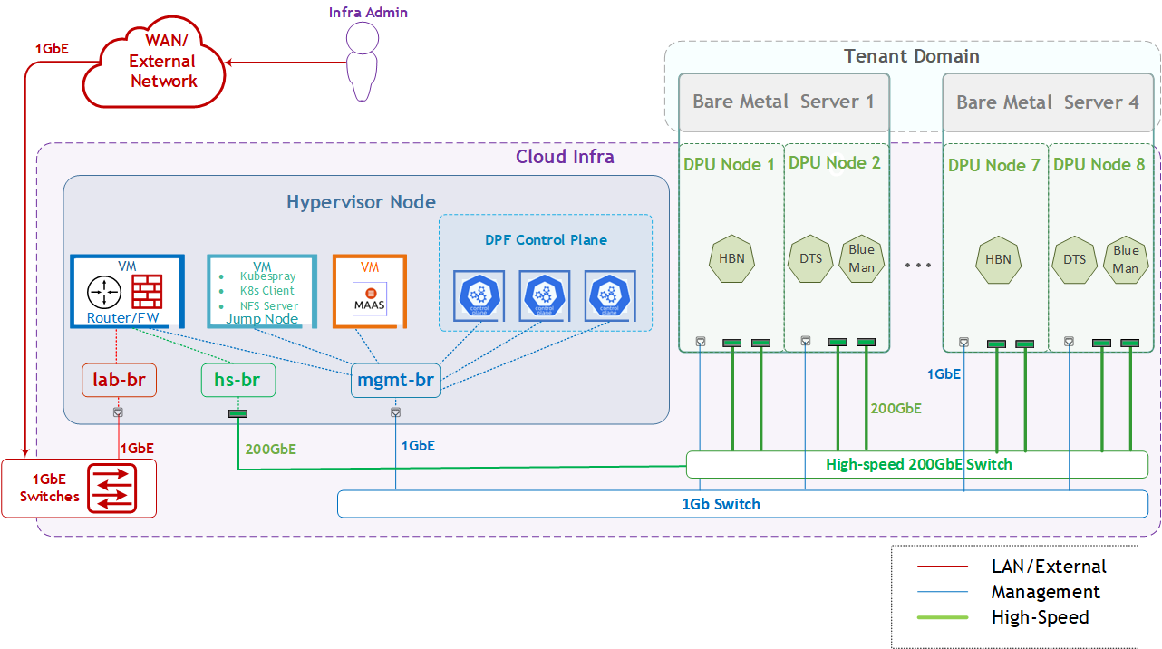
The logical design includes the following components:
-
1 x Hypervisor node (KVM-based) with ConnectX-7:
-
1 x Firewall VM
-
1 x Jump Node VM
-
1 x MaaS VM
-
3 x K8s Master VMs running all K8s management components
-
-
4 x Worker nodes (PCI Gen5), each with 2 x BlueField-3 NIC
-
Single High-Speed (HS) switch
-
1 Gb Host Management network
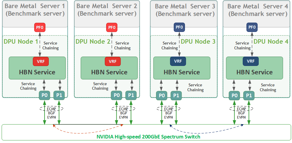
HBN service Logical Design
As part of this RDG, we will:
-
Create two fully isolated logical networks per bare-metal workload server using a single physical function (PF0).
-
Connect each network through the HBN service to a dedicated VLAN/VNI, mapped to separate VRFs (RED or BLUE).
-
-
Route all workload traffic through the HBN service, with routing and isolation enforced inside the DPU.
-
Assign PF0 as the sole network interface for each bare-metal workload server, with no networking configuration on the host.
-
Demonstrate accelerated RDMA and TCP traffic between workload servers running on different bare-metal hosts within the same network (for example, RED ↔ RED).
-
Validate strict network isolation by confirming that traffic between workloads in different networks (RED vs BLUE) is not permitted.
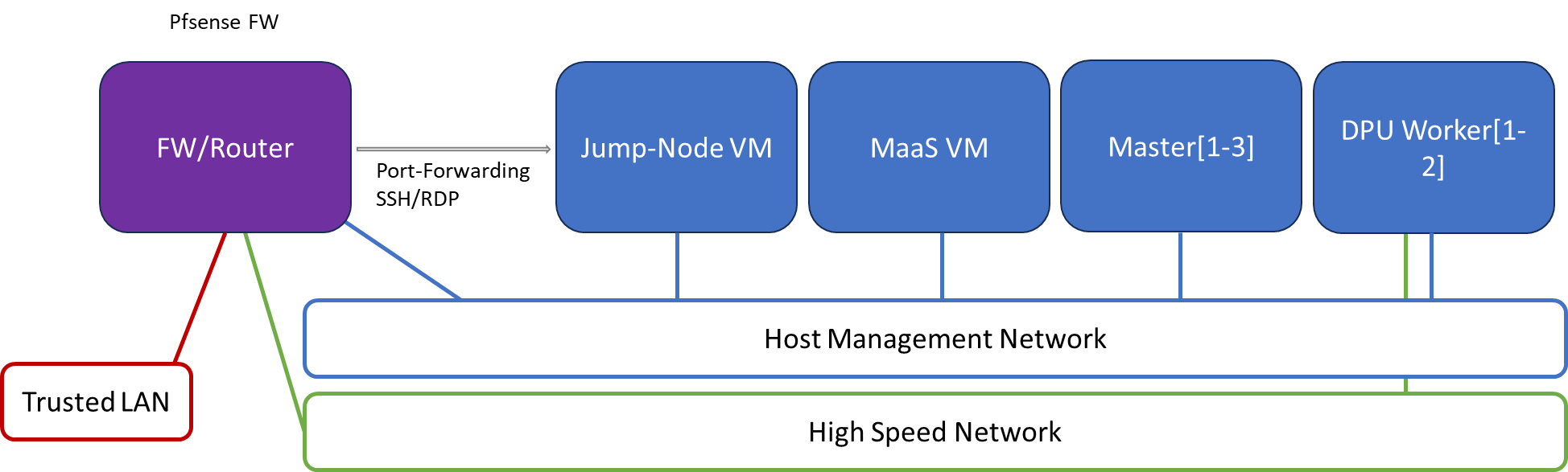
Firewall Design
The pfSense firewall in this solution serves a dual purpose:
-
Firewall—provides an isolated environment for the DPF system, ensuring secure operations
-
Router—enables Internet access for the management network
Port-forwarding rules for SSH and RDP are configured on the firewall to route traffic to the jump node’s IP address in the host management network. From the jump node, administrators can manage and access various devices in the setup, as well as handle the deployment of the Kubernetes (K8s) cluster and DPF components.
The following diagram illustrates the firewall design used in this solution:
Software Stack Components
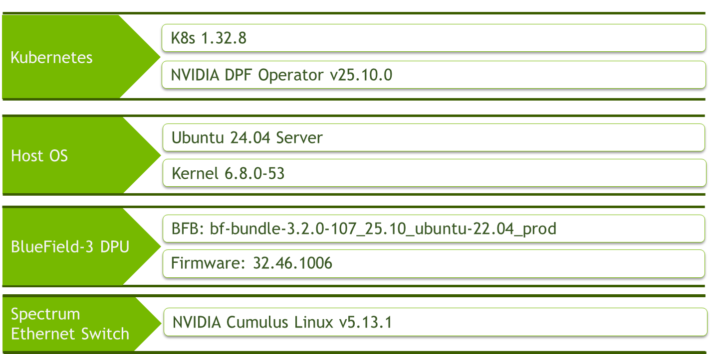
Make sure to use the exact same versions for the software stack as described above.
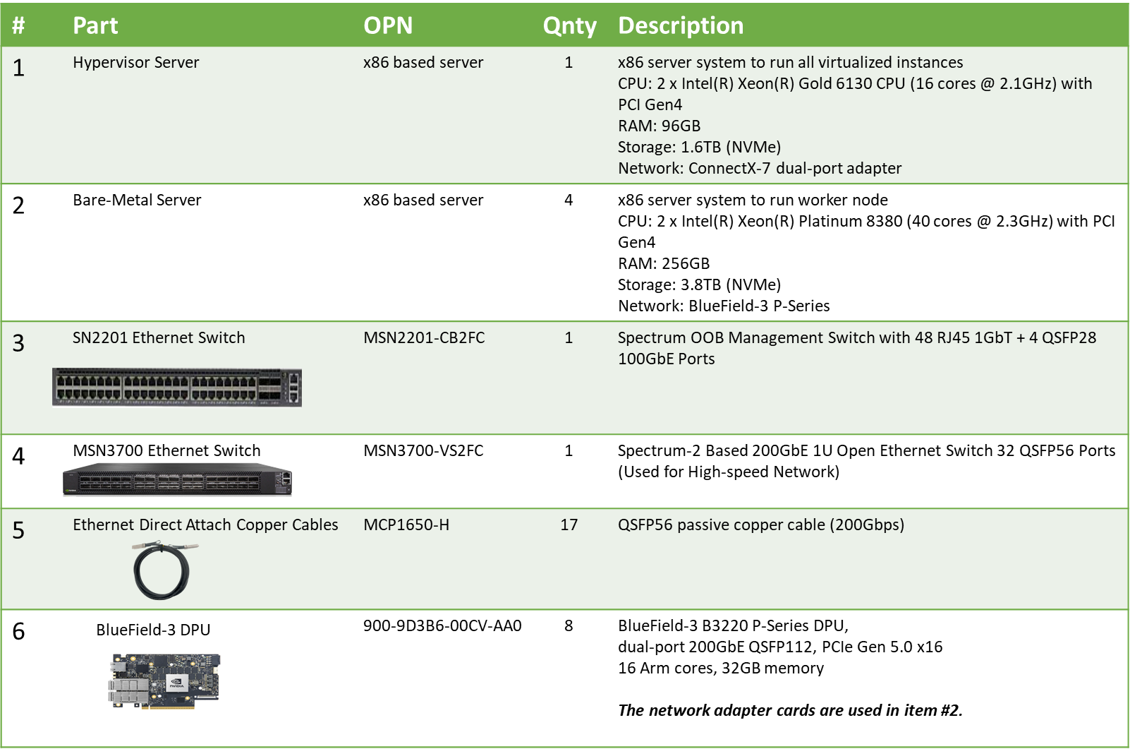
Bill of Materials
Deployment and Configuration
Node and Switch Definitions
These are the definitions and parameters used for deploying the demonstrated fabric:
|
Switches Ports Usage |
||
|---|---|---|
|
Hostname |
Rack ID |
Ports |
|
|
1 |
swp1-3 |
|
|
1 |
swp1-17 |
|
Hosts |
|||||
|---|---|---|---|---|---|
|
Rack |
Server Type |
Server Name |
Switch Port |
IP and NICs |
Default Gateway |
|
Rack1
|
Hypervisor Node |
|
mgmt-switch: hs-switch: |
lab-br (interface eno1): Trusted LAN IP mgmt-br (interface eno2): - hs-br (interface enp1s0): - |
Trusted LAN GW |
|
Rack1 |
Firewall (Virtual) |
|
- |
WAN (lab-br): Trusted LAN IP LAN (mgmt-br): 10.0.110.254/24 OPT1(hs-br): 10.0.123.254/22 |
Trusted LAN GW |
|
Rack1 |
Jump Node (Virtual) |
|
- |
enp1s0: 10.0.110.253/24 |
10.0.110.254 |
|
Rack1 |
MaaS (Virtual) |
|
- |
enp1s0: 10.0.110.252/24 |
10.0.110.254 |
|
Rack1 |
Master Node
|
|
- |
enp1s0: 10.0.110.1/24 |
10.0.110.254 |
|
Rack1 |
Master Node
|
|
- |
enp1s0: 10.0.110.2/24 |
10.0.110.254 |
|
Rack1 |
Master Node
|
|
- |
enp1s0: 10.0.110.3/24 |
10.0.110.254 |
|
Rack1
|
Worker Node |
|
mgmt-switch: hs-switch: |
dpubmc: 10.0.110.21/24 ens1f0np0/ens1f1np1: 10.0.120.0/22 |
10.0.110.254 |
|
Rack1
|
Worker Node |
|
mgmt-switch: hs-switch: |
dpubmc: 10.0.110.22/24 ens1f0np0/ens1f1np1: 10.0.120.0/22 |
10.0.110.254 |
|
Rack1
|
Worker Node |
|
mgmt-switch: hs-switch: |
dpubmc: 10.0.110.23/24 ens1f0np0/ens1f1np1: 10.0.120.0/22 |
10.0.110.254 |
|
Rack1
|
Worker Node |
|
mgmt-switch: hs-switch: |
dpubmc: 10.0.110.24/24 ens1f0np0/ens1f1np1: 10.0.120.0/22 |
10.0.110.254 |
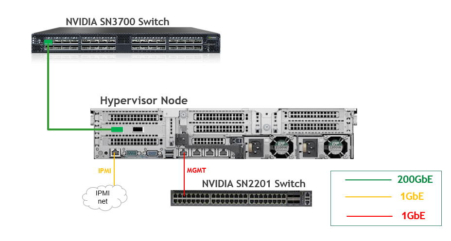
Wiring
Hypervisor Node
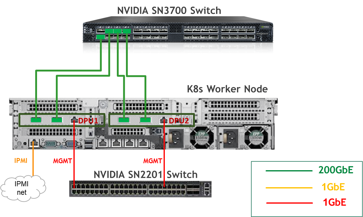
Bare Metal Worker Node
Fabric Configuration
Updating Cumulus Linux
As a best practice, make sure to use the latest released Cumulus Linux NOS version.
For information on how to upgrade Cumulus Linux, refer to the Cumulus Linux User Guide.
Configuring the Cumulus Linux Switch
The SN3700 switch (hs-switch), is configured as follows:
The SN2201 switch (mgmt-switch) is configured as follows:
Host Configuration
Make sure that the BIOS settings on the worker node servers have SR-IOV enabled and that the servers are tuned for maximum performance.
All worker nodes must have the same PCIe placement for the BlueField-3 NIC and must display the same interface name.
Make sure that you have DPU BMC and OOB MAC addresses.
No change from the Reference Deployment Guide (Baseline RDG) (Section "Deployment and Configuration", Subsection "Host Configuration").
Hypervisor Installation and Configuration
No change from the Baseline RDG (Section "Deployment and Configuration", Subsection "Hypervisor Installation and Configuration").
Prepare Infrastructure Servers
No change from the Baseline RDG (Section "Deployment and Configuration", Subsection "Prepare Infrastructure Servers") regarding Firewall VM, Jump VM, MaaS VM.
(Optional) Firewall VM – Bare Metal Server Outside Conection
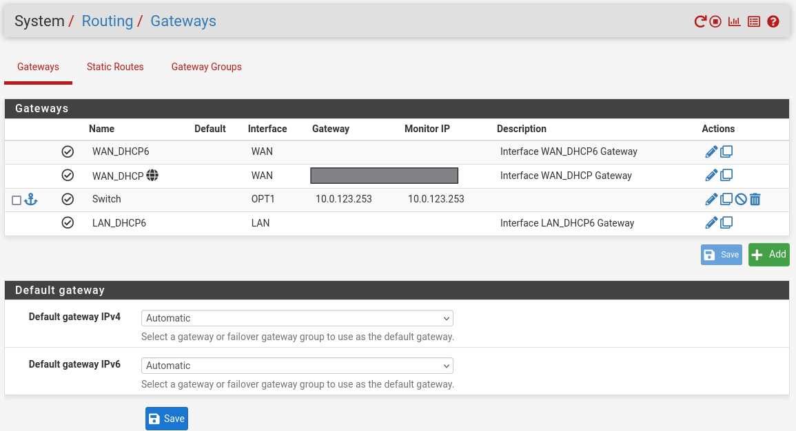
To provide outside connection from Bare Metal Host via High Speed network, open Firefox web browser and go to the pfSense web UI (http://10.0.110.254).
-
System:
-
Routing → Gateways → Add → “Interface”: OPT1, “Address Family”: IPv4, “Name”: switch, “Gateway”: 10.0.123.253 → Click "Save"→ Under "Default Gateway" - "Default gateway IPv4" choose WAN_DHCP → Click "Save"
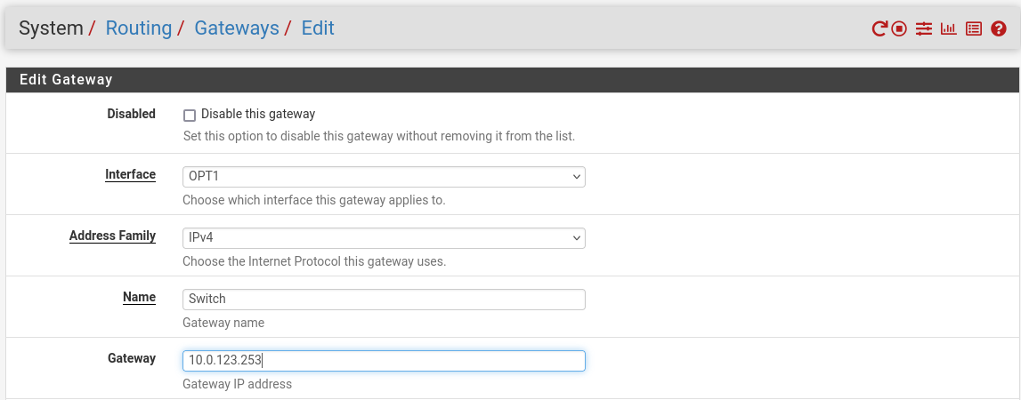
Note that the IP addresses from the Trusted LAN network under "Gateway" and "Monitor IP" are blurred.
-
Provision Master VMs Using MaaS
No change from the Baseline RDG (Section "Deployment and Configuration", Subsection "Provision Master VMs Using MaaS").
K8s Cluster Deployment and Configuration
The procedures for initial Kubernetes cluster deployment using Kubespray for the master nodes, and subsequent verification, remain unchanged from the Baseline RDG (Section "K8s Cluster Deployment and Configuration", Subsections: "Kubespray Deployment and Configuration", "Deploying Cluster Using Kubespray Ansible Playbook","K8s Deployment Verification".
DPF Installation
The DPF installation process (Operator, System components) largely follows the Baseline RDG.
Software Prerequisites and Required Variables
-
Start by installing the remaining software perquisites.
Jump Node Console
## Connect to master1 to copy helm client utility that was installed during kubespray deployment $ depuser@jump:~$ ssh master1 depuser@master1:~$ cp /usr/local/bin/helm /tmp/ ## In another tab depuser@jump:~$ scp master1:/tmp/helm /tmp/ depuser@jump:~$ sudo chown root:root /tmp/helm depuser@jump:~$ sudo mv /tmp/helm /usr/local/bin/ ## Verify that envsubst utility is installed depuser@jump:~$ which envsubst /usr/bin/envsubst -
Proceed to clone the doca-platform Git repository:
Jump Node Console
$ git clone https://github.com/NVIDIA/doca-platform.git -
Change directory to doca-platform and checkout to tag v25.10.0:
Jump Node Console
$ cd doca-platform/ $ git checkout v25.10.0 -
Change directory to readme.md from where all the commands will be run:
Jump Node Console
$ cd doca-platform/docs/public/user-guides/zero-trust/use-cases/hbn -
Change the BMC root's password.
In Zero Trust mode, provisioning DPUs requires authentication with Redfish.
In order to do that, you must set the same root password to access the BMC for all DPUs DPF is going to manage.For more information on how to set the BMC root password refer to BlueField DPU Administrator Quick Start Guide.Connect to the DPU BMC over SSH to change the BMC root's password on all DPUs.
Jump Node Console
$ ssh root@10.0.110.201 root@10.0.110.201's password: <BMC Root Password. Default root/0penBmc. need to change first time to $BMC_ROOT_PASSWORD in the manifests/00-env-vars/envvars.env file> -
Modify the variables in
manifests/00-env-vars/envvars.envto fit your environment, then source the file:Replace the values for the variables in the following file with the values that fit your setup. Specifically, pay attention to
DPUCLUSTER_INTERFACE,BMC_ROOT_PASSWORD, andDPU's serial number.
To get aDPU's serial numberyou can use following command. Sample:
$ curl -k -u root:'BMC root password' https://10.0.110.201/redfish/v1/Systems/Bluefield | jq -r '.SerialNumber | ascii_downcase'
% Total % Received % Xferd Average Speed Time Time Time Current
Dload Upload Total Spent Left Speed
100 4970 100 4970 0 0 4211 0 0:00:01 0:00:01 --:--:-- 4211
mt2402xz0f7xmanifests/00-env-vars/envvars.env
Bash## IP Address for the Kubernetes API server of the target cluster on which DPF is installed. ## This should never include a scheme or a port. ## e.g. 10.10.10.10 export TARGETCLUSTER_API_SERVER_HOST=10.0.110.10 ## Virtual IP used by the load balancer for the DPU Cluster. Must be a reserved IP from the management subnet and not ## allocated by DHCP. export DPUCLUSTER_VIP=10.0.110.200 ## Interface on which the DPUCluster load balancer will listen. Should be the management interface of the control plane node. export DPUCLUSTER_INTERFACE=ens160 ## IP address to the NFS server used as storage for the BFB. export NFS_SERVER_IP=10.0.110.253 ## The repository URL for the NVIDIA Helm chart registry. ## Usually this is the NVIDIA Helm NGC registry. For development purposes, this can be set to a different repository. export HELM_REGISTRY_REPO_URL=https://helm.ngc.nvidia.com/nvidia/doca ## The repository URL for the HBN container image. ## Usually this is the NVIDIA NGC registry. For development purposes, this can be set to a different repository. export HBN_NGC_IMAGE_URL=nvcr.io/nvidia/doca/doca_hbn ## The DPF REGISTRY is the Helm repository URL where the DPF Operator Chart resides. ## Usually this is the NVIDIA Helm NGC registry. For development purposes, this can be set to a different repository. export REGISTRY=https://helm.ngc.nvidia.com/nvidia/doca ## The DPF TAG is the version of the DPF components which will be deployed in this guide. export TAG=v25.10.0 ## URL to the BFB used in the `bfb.yaml` and linked by the DPUSet. export BFB_URL="https://content.mellanox.com/BlueField/BFBs/Ubuntu24.04/bf-bundle-3.2.1-34_25.11_ubuntu-24.04_64k_prod.bfb" ## IP_RANGE_START and IP_RANGE_END ## These define the IP range for DPU discovery via Redfish/BMC interfaces ## Example: If your DPUs have BMC IPs in range 10.0.110.201-224 ## export IP_RANGE_START=10.0.110.201 ## export IP_RANGE_END=10.0.110.224 ## Start of DPUDiscovery IpRange export IP_RANGE_START=10.0.110.201 ## End of DPUDiscovery IpRange export IP_RANGE_END=10.0.110.208 # The password used for DPU BMC root login, must be the same for all DPUs # For more information on how to set the BMC root password refer to BlueField DPU Administrator Quick Start Guide. export BMC_ROOT_PASSWORD=<set your BMC_ROOT_PASSWORD> ## Serial number of DPUs. If you have more than 2 DPUs, you will need to parameterize the system accordingly and expose ## additional variables. ## All serial numbers must be in lowercase. ## Serial number of DPU1 export DPU1_SERIAL=mt2402xz0f7x ## Serial number of DPU2 export DPU2_SERIAL=mt2402xz0f80 ## Serial number of DPU3 export DPU2_SERIAL=mt2402xz0f9n ## Serial number of DPU4 export DPU2_SERIAL=mt2402xz0f8g -
Export environment variables for the installation:
Jump Node Console
$ source manifests/00-env-vars/envvars.env
DPF Operator Installation
No change from the Baseline RDG (Section "DPF Installation", Subsection "DPF Operator Installation").
DPF System Installation
No change from the Baseline RDG (Section "DPF Installation", Subsection "DPF System Installation").
DPU Services Installation
HBN DPU Service Installation
This section focuses on provisioning NVIDIA®BlueField®-3 DPUs using DPF, installing the HBN DPU Service on those DPUs and enabling workload traffic to pass through HBN before leaving the DPU.
-
Export environment variables for the installation:
Jump Node Console
$ source manifests/00-env-vars/envvars.env -
Use the following YAML to define a
BFBresource that downloads the Bluefield Bitstream to a shared volume:--- apiVersion: provisioning.dpu.nvidia.com/v1alpha1 kind: BFB metadata: name: bf-bundle-$TAG namespace: dpf-operator-system spec: url: $BFB_URL -
Change the DPUFlavor using the following YAML.
--- apiVersion: provisioning.dpu.nvidia.com/v1alpha1 kind: DPUFlavor metadata: name: hbn-$TAG namespace: dpf-operator-system spec: dpuMode: zero-trust bfcfgParameters: - UPDATE_ATF_UEFI=yes - UPDATE_DPU_OS=yes - WITH_NIC_FW_UPDATE=yes configFiles: - operation: override path: /etc/mellanox/mlnx-bf.conf permissions: "0644" raw: | ALLOW_SHARED_RQ="no" IPSEC_FULL_OFFLOAD="no" ENABLE_ESWITCH_MULTIPORT="yes" - operation: override path: /etc/mellanox/mlnx-ovs.conf permissions: "0644" raw: | CREATE_OVS_BRIDGES="no" OVS_DOCA="yes" - operation: override path: /etc/mellanox/mlnx-sf.conf permissions: "0644" raw: "" grub: kernelParameters: - console=hvc0 - console=ttyAMA0 - earlycon=pl011,0x13010000 - fixrttc - net.ifnames=0 - biosdevname=0 - iommu.passthrough=1 - cgroup_no_v1=net_prio,net_cls - hugepagesz=2048kB - hugepages=3072 nvconfig: - device: '*' parameters: - PF_BAR2_ENABLE=0 - PER_PF_NUM_SF=1 - PF_TOTAL_SF=20 - PF_SF_BAR_SIZE=10 - NUM_PF_MSIX_VALID=0 - PF_NUM_PF_MSIX_VALID=1 - PF_NUM_PF_MSIX=228 - INTERNAL_CPU_MODEL=1 - INTERNAL_CPU_OFFLOAD_ENGINE=0 - SRIOV_EN=1 - NUM_OF_VFS=46 - LAG_RESOURCE_ALLOCATION=1 - LINK_TYPE_P1=ETH - LINK_TYPE_P2=ETH - EXP_ROM_UEFI_x86_ENABLE=1 ovs: rawConfigScript: | _ovs-vsctl() { ovs-vsctl --no-wait --timeout 15 "$@" } _ovs-vsctl set Open_vSwitch . other_config:doca-init=true _ovs-vsctl set Open_vSwitch . other_config:dpdk-max-memzones=50000 _ovs-vsctl set Open_vSwitch . other_config:hw-offload=true _ovs-vsctl set Open_vSwitch . other_config:pmd-quiet-idle=true _ovs-vsctl set Open_vSwitch . other_config:max-idle=20000 _ovs-vsctl set Open_vSwitch . other_config:max-revalidator=5000 _ovs-vsctl --if-exists del-br ovsbr1 _ovs-vsctl --if-exists del-br ovsbr2 _ovs-vsctl --may-exist add-br br-sfc _ovs-vsctl set bridge br-sfc datapath_type=netdev _ovs-vsctl set bridge br-sfc fail_mode=secure _ovs-vsctl --may-exist add-port br-sfc p0 _ovs-vsctl set Interface p0 type=dpdk _ovs-vsctl set Interface p0 mtu_request=9216 _ovs-vsctl set Port p0 external_ids:dpf-type=physical _ovs-vsctl --may-exist add-port br-sfc p1 _ovs-vsctl set Interface p1 type=dpdk _ovs-vsctl set Interface p1 mtu_request=9216 _ovs-vsctl set Port p1 external_ids:dpf-type=physical _ovs-vsctl --may-exist add-br br-hbn _ovs-vsctl set bridge br-hbn datapath_type=netdev _ovs-vsctl set bridge br-hbn fail_mode=secure -
In multi-DPU configurations—where a single host worker node includes two or more NVIDIA® BlueField® DPUs—using a standard
nodeSelectortargets the host node rather than individual DPUs. As a result, all DPU-scoped services (HBN, DTS, BlueMan) are deployed onto every DPU on that node, which may lead to service conflicts and prevents proper role separation across DPUs.The
dpuSelectormechanism provides fine-grained control over service placement by enabling operators to target specific DPUs directly. This approach improves resource allocation, enforces service isolation, and enables clean scalability in multi-DPU deployments.Using
dpuSelector, you can:-
Run the HBN service exclusively on the first DPU.
-
Deploy the DTS and BlueMan services on the second DPU.
To target a specific DPU, apply labels to the corresponding
DPUDeviceobject. The labeled device can then be referenced bydpuSelector.
Below is an example (replace the serial number with the one from your environment):Jump Node Console
$ kubectl label dpudevice -n dpf-operator-system mt2402xz0f7x mt2402xz0f80 mt2402xz0f9n mt2402xz0f8g provisioning.dpu.nvidia.com/dpudevice-service-name=hbn $ kubectl label dpudevice -n dpf-operator-system mt2511600rc3 mt2511600ruh mt2511600r8p mt2511600rp1 provisioning.dpu.nvidia.com/dpudevice-service-name=dts-blueman -
-
Change the
dpudeployment.yamlfile to reference the DPUFlavor.--- apiVersion: svc.dpu.nvidia.com/v1alpha1 kind: DPUDeployment metadata: name: hbn-only namespace: dpf-operator-system spec: dpus: bfb: bf-bundle-$TAG flavor: hbn-$TAG nodeEffect: hold: true dpuSets: - nameSuffix: "dpuset1" nodeSelector: matchLabels: feature.node.kubernetes.io/dpu-enabled: "true" dpuSelector: provisioning.dpu.nvidia.com/dpudevice-service-name: hbn services: doca-hbn: serviceTemplate: doca-hbn serviceConfiguration: doca-hbn serviceChains: switches: - ports: - serviceInterface: matchLabels: uplink: p0 - service: name: doca-hbn interface: p0_if - ports: - serviceInterface: matchLabels: uplink: p1 - service: name: doca-hbn interface: p1_if - ports: - serviceInterface: matchLabels: interface: pf0hpf - service: interface: pf0hpf_if name: doca-hbnPlease notice that with default nodeEffect above, DPU provisioning workflow will be paused and wait for an external signal (annotation) in order to proceed, as demonstrated in upcoming steps.
To implement a fully automated process that won’t require user intervention, see customAction option. -
Change the rest of the configuration files.
As explained in the introduction, these files create service chains that connect two physical functions PF0(RED) or PF0(BLUE) to the outer fabric through HBN, providing EVPN VXLAN overlay, VNI based isolation, and ECMP redundancy across both DPU uplinks (p0 and p1).
These are the configuration files.-
HBN DPUServiceConfig and DPUServiceTemplate to deploy HBN workloads to the DPUs.
---
apiVersion: svc.dpu.nvidia.com/v1alpha1
kind: DPUServiceConfiguration
metadata:
  name: doca-hbn
  namespace: dpf-operator-system
spec:
  deploymentServiceName: "doca-hbn"
  serviceConfiguration:
    serviceDaemonSet:
      annotations:
        k8s.v1.cni.cncf.io/networks: |-
          [
            {"name": "iprequest", "interface": "ip_lo", "cni-args": {"poolNames": ["loopback"], "poolType": "cidrpool"}},
            {"name": "iprequest", "interface": "ip_pf0hpf_red", "cni-args": {"poolNames": ["pool1"], "poolType": "cidrpool", "allocateDefaultGateway": true}},
            {"name": "iprequest", "interface": "ip_pf0hpf_blue", "cni-args": {"poolNames": ["pool2"], "poolType": "cidrpool", "allocateDefaultGateway": true}}
          ]

    helmChart:
      values:
        configuration:
          perDPUValuesYAML: |
            - hostnamePattern: "*"
              values:
                bgp_peer_group: hbn

            # ---- DPU1, DPU2 => RED only ----
            - hostnamePattern: "dpu-node-${DPU1_SERIAL}-${DPU1_SERIAL}"
              values:
                role: RED
                vrf: RED
                vlan: 11
                l2vni: 10010
                l3vni: 100001
                bgp_autonomous_system: 65101

            - hostnamePattern: "dpu-node-${DPU2_SERIAL}-${DPU2_SERIAL}"
              values:
                role: RED
                vrf: RED
                vlan: 11
                l2vni: 10010
                l3vni: 100001
                bgp_autonomous_system: 65201

            # ---- DPU3, DPU4 => BLUE only ----
            - hostnamePattern: "dpu-node-${DPU3_SERIAL}-${DPU3_SERIAL}"
              values:
                role: BLUE
                vrf: BLUE
                vlan: 21
                l2vni: 10020
                l3vni: 100002
                bgp_autonomous_system: 65301

            - hostnamePattern: "dpu-node-${DPU4_SERIAL}-${DPU4_SERIAL}"
              values:
                role: BLUE
                vrf: BLUE
                vlan: 21
                l2vni: 10020
                l3vni: 100002
                bgp_autonomous_system: 65401

          startupYAMLJ2: |
            - header:
                model: bluefield
                nvue-api-version: nvue_v1
                rev-id: 1.0
                version: HBN 2.4.0

            - set:
                bridge:
                  domain:
                    br_default:
                      vlan:
                        {{ config.vlan }}:
                          vni:
                            {{ config.l2vni }}: {}

                evpn:
                  enable: on
                  route-advertise: {}

                interface:
                  lo:
                    ip:
                      address:
                        {{ ipaddresses.ip_lo.ip }}/32: {}
                    type: loopback

                  p0_if,p1_if,pf0hpf_if:
                    type: swp
                    link:
                      mtu: 9000

                  pf0hpf_if:
                    bridge:
                      domain:
                        br_default:
                          access: {{ config.vlan }}

                  vlan{{ config.vlan }}:
                    type: svi
                    vlan: {{ config.vlan }}
                    ip:
                      address:
                        {% if config.role == "RED" %}
                        {{ ipaddresses.ip_pf0hpf_red.cidr }}: {}
                        {% else %}
                        {{ ipaddresses.ip_pf0hpf_blue.cidr }}: {}
                        {% endif %}
                      vrf: {{ config.vrf }}

                nve:
                  vxlan:
                    arp-nd-suppress: on
                    enable: on
                    source:
                      address: {{ ipaddresses.ip_lo.ip }}

                router:
                  bgp:
                    enable: on
                    graceful-restart:
                      mode: full

                vrf:
                  default:
                    router:
                      bgp:
                        address-family:
                          ipv4-unicast:
                            enable: on
                            redistribute:
                              connected:
                                enable: on
                          l2vpn-evpn:
                            enable: on
                        autonomous-system: {{ config.bgp_autonomous_system }}
                        enable: on
                        neighbor:
                          p0_if:
                            peer-group: {{ config.bgp_peer_group }}
                            type: unnumbered
                          p1_if:
                            peer-group: {{ config.bgp_peer_group }}
                            type: unnumbered
                        path-selection:
                          multipath:
                            aspath-ignore: on
                        peer-group:
                          {{ config.bgp_peer_group }}:
                            address-family:
                              ipv4-unicast:
                                enable: on
                              l2vpn-evpn:
                                enable: on
                            remote-as: external
                        router-id: {{ ipaddresses.ip_lo.ip }}

                  {{ config.vrf }}:
                    evpn:
                      enable: on
                      vni:
                        {{ config.l3vni }}: {}
                    loopback:
                      ip:
                        address:
                          {{ ipaddresses.ip_lo.ip }}/32: {}
                    router:
                      bgp:
                        address-family:
                          ipv4-unicast:
                            enable: on
                            redistribute:
                              connected:
                                enable: on
                            route-export:
                              to-evpn:
                                enable: on
                        autonomous-system: {{ config.bgp_autonomous_system }}
                        enable: on
                        router-id: {{ ipaddresses.ip_lo.ip }}

  interfaces:
    - name: p0_if
      network: mybrhbn
    - name: p1_if
      network: mybrhbn
    - name: pf0hpf_if
      network: mybrhbn
--- apiVersion: svc.dpu.nvidia.com/v1alpha1 kind: DPUServiceTemplate metadata: name: doca-hbn namespace: dpf-operator-system spec: deploymentServiceName: "doca-hbn" helmChart: source: repoURL: $HELM_REGISTRY_REPO_URL version: 1.0.5 chart: doca-hbn values: image: repository: $HBN_NGC_IMAGE_URL tag: 3.2.1-doca3.2.1 resources: memory: 6Gi nvidia.com/bf_sf: 4 -
Physical Interfaces for physical ports on the DPU.
--- apiVersion: svc.dpu.nvidia.com/v1alpha1 kind: DPUServiceInterface metadata: name: p0 namespace: dpf-operator-system spec: template: spec: template: metadata: labels: uplink: "p0" spec: interfaceType: physical physical: interfaceName: p0 --- apiVersion: svc.dpu.nvidia.com/v1alpha1 kind: DPUServiceInterface metadata: name: p1 namespace: dpf-operator-system spec: template: spec: template: metadata: labels: uplink: "p1" spec: interfaceType: physical physical: interfaceName: p1 --- apiVersion: svc.dpu.nvidia.com/v1alpha1 kind: DPUServiceInterface metadata: name: pf0hpf namespace: dpf-operator-system spec: template: spec: template: metadata: labels: interface: "pf0hpf" spec: interfaceType: pf pf: pfID: 0 -
DPU Service IPAM objects to set up IP Address Management on the DPUCluster.
---
apiVersion: svc.dpu.nvidia.com/v1alpha1
kind: DPUServiceIPAM
metadata:
  name: pool1
  namespace: dpf-operator-system
spec:
  ipv4Network:
    network: "10.0.121.0/24"
    gatewayIndex: 2
    prefixSize: 29
    # These preallocations are not necessary. We specify them so that the validation commands are straightforward.
    allocations:
      dpu-node-${DPU1_SERIAL}-${DPU1_SERIAL}: 10.0.121.0/29
      dpu-node-${DPU2_SERIAL}-${DPU2_SERIAL}: 10.0.121.8/29
---
apiVersion: svc.dpu.nvidia.com/v1alpha1
kind: DPUServiceIPAM
metadata:
  name: pool2
  namespace: dpf-operator-system
spec:
  ipv4Network:
    network: "10.0.122.0/24"
    gatewayIndex: 2
    prefixSize: 29
    allocations:
      dpu-node-${DPU3_SERIAL}-${DPU3_SERIAL}: 10.0.122.0/29
      dpu-node-${DPU4_SERIAL}-${DPU4_SERIAL}: 10.0.122.8/29
--- apiVersion: svc.dpu.nvidia.com/v1alpha1 kind: DPUServiceIPAM metadata: name: loopback namespace: dpf-operator-system spec: ipv4Network: network: "11.0.0.0/24" prefixSize: 32It is necessary to set several environment variables before running this command.
$ source manifests/00-env-vars/envvars.env
-
-
Apply all of the YAML files mentioned above using the following command:
Jump Node Console
$ cat manifests/03.1-dpudeployment-installation-pf/*.yaml | envsubst | kubectl apply -f -Jump Node Console
$ kubectl wait --for=condition=ApplicationsReconciled --namespace dpf-operator-system dpuservices --all dpuservice.svc.dpu.nvidia.com/doca-hbn-wb5pg condition met dpuservice.svc.dpu.nvidia.com/flannel condition met dpuservice.svc.dpu.nvidia.com/multus condition met dpuservice.svc.dpu.nvidia.com/nvidia-k8s-ipam condition met dpuservice.svc.dpu.nvidia.com/ovs-cni condition met dpuservice.svc.dpu.nvidia.com/servicechainset-controller condition met dpuservice.svc.dpu.nvidia.com/servicechainset-rbac-and-crds condition met dpuservice.svc.dpu.nvidia.com/sfc-controller condition met dpuservice.svc.dpu.nvidia.com/sriov-device-plugin condition met $ kubectl wait --for=condition=DPUIPAMObjectReconciled --namespace dpf-operator-system dpuserviceipam --all dpuserviceipam.svc.dpu.nvidia.com/loopback condition met dpuserviceipam.svc.dpu.nvidia.com/pool1 condition met dpuserviceipam.svc.dpu.nvidia.com/pool2 condition met $ kubectl wait --for=condition=ServiceInterfaceSetReconciled --namespace dpf-operator-system dpuserviceinterface --all dpuserviceinterface.svc.dpu.nvidia.com/doca-hbn-p0-if-vjqn5 condition met dpuserviceinterface.svc.dpu.nvidia.com/doca-hbn-p1-if-nl8rj condition met dpuserviceinterface.svc.dpu.nvidia.com/doca-hbn-pf0hpf-if-kbfj4 condition met dpuserviceinterface.svc.dpu.nvidia.com/doca-hbn-pf1hpf-if-79zsq condition met dpuserviceinterface.svc.dpu.nvidia.com/p0 condition met dpuserviceinterface.svc.dpu.nvidia.com/p1 condition met dpuserviceinterface.svc.dpu.nvidia.com/pf0hpf condition met dpuserviceinterface.svc.dpu.nvidia.com/pf1hpf condition met $ kubectl wait --for=condition=ServiceChainSetReconciled --namespace dpf-operator-system dpuservicechain --all dpuservicechain.svc.dpu.nvidia.com/hbn-only-8xrrx condition met -
To follow the progress of DPU provisioning, run the following command to check its current phase:Jump Node Console
$ watch -n10 "kubectl describe dpu -n dpf-operator-system | grep 'Node Name\|Type\|Last\|Phase'"
-
Wait for the NodeEffect stage (at this point the provisioning is paused, waintig for external signal).
Run following command on all/specific DPU nodemaintanace object/s to proceed with provisioning:Jump Node Console
$ kubectl annotate dpunodemaintenances -n dpf-operator-system --all provisioning.dpu.nvidia.com/wait-for-external-nodeeffect=false --overwrite -
To follow the progress of DPU provisioning, run the following command to check its current phase:Jump Node Console
$ watch -n10 "kubectl describe dpu -n dpf-operator-system | grep 'Node Name\|Type\|Last\|Phase'" Every 10.0s: kubectl describe dpu -n dpf-operator-system | grep 'Node Name\|Type\|Last\|Phase' setup5-jump: Wed Jan 7 10:47:25 2026 Dpu Node Name: dpu-node-mt2402xz0f7x Last Transition Time: 2026-01-07T08:31:53Z Type: BFBPrepared Last Transition Time: 2026-01-07T08:31:49Z Type: BFBReady Last Transition Time: 2026-01-07T08:36:38Z Type: BFBTransferred Last Transition Time: 2026-01-07T08:31:52Z Type: FWConfigured Last Transition Time: 2026-01-07T08:31:49Z Type: Initialized Last Transition Time: 2026-01-07T08:31:50Z Type: InterfaceInitialized Last Transition Time: 2026-01-07T08:31:49Z Type: NodeEffectReady Last Transition Time: 2026-01-07T08:43:33Z Reason: OemLastState Type: OSInstalled Last Transition Time: 2026-01-07T08:46:37Z Type: Rebooted Phase: Rebooting Dpu Node Name: dpu-node-mt2402xz0f80 Last Transition Time: 2026-01-07T08:31:52Z Type: BFBPrepared Last Transition Time: 2026-01-07T08:31:49Z Type: BFBReady Last Transition Time: 2026-01-07T08:36:33Z Type: BFBTransferred Last Transition Time: 2026-01-07T08:31:51Z Type: FWConfigured Last Transition Time: 2026-01-07T08:31:49Z Type: Initialized Last Transition Time: 2026-01-07T08:31:49Z Type: InterfaceInitialized Last Transition Time: 2026-01-07T08:31:49Z Type: NodeEffectReady Last Transition Time: 2026-01-07T08:43:19Z Reason: OemLastState Type: OSInstalled Last Transition Time: 2026-01-07T08:46:23Z Type: Rebooted Phase: Rebooting ... -
Wait for the Rebooted stage and then Power Cycle the bare-metal host manual.
After the DPU is up, run following command for each DPU worker:Jump Node Console
$ kubectl -n dpf-operator-system annotate dpunode dpu-node-mt2402xz0f7x dpu-node-mt2402xz0f80 dpu-node-mt2402xz0f9n dpu-node-mt2402xz0f8g provisioning.dpu.nvidia.com/dpunode-external-reboot-required- -
At this point, the DPU workers should be added to the cluster. As they being added to the cluster, the DPUs are provisioned.
Jump Node Console
$ watch -n10 "kubectl describe dpu -n dpf-operator-system | grep 'Node Name\|Type\|Last\|Phase'" Every 10.0s: kubectl describe dpu -n dpf-operator-system | grep 'Node Name\|Type\|Last\|Phase' setup5-jump: Wed Jan 7 11:10:49 2026 Dpu Node Name: dpu-node-mt2402xz0f7x Type: InternalIP Type: Hostname Last Transition Time: 2026-01-07T09:09:57Z Type: Ready Last Transition Time: 2026-01-07T08:31:53Z Type: BFBPrepared Last Transition Time: 2026-01-07T08:31:49Z Type: BFBReady Last Transition Time: 2026-01-07T08:36:38Z Type: BFBTransferred Last Transition Time: 2026-01-07T09:09:57Z Type: DPUClusterReady Last Transition Time: 2026-01-07T08:31:52Z Type: FWConfigured Last Transition Time: 2026-01-07T08:31:49Z Type: Initialized Last Transition Time: 2026-01-07T08:31:50Z Type: InterfaceInitialized Last Transition Time: 2026-01-07T08:31:49Z Type: NodeEffectReady Last Transition Time: 2026-01-07T09:09:57Z Type: NodeEffectRemoved Last Transition Time: 2026-01-07T08:43:33Z Reason: OemLastState Type: OSInstalled Last Transition Time: 2026-01-07T09:09:57Z Type: Rebooted Phase: Ready Dpu Node Name: dpu-node-mt2402xz0f80 Type: InternalIP Type: Hostname Last Transition Time: 2026-01-07T09:10:24Z Type: Ready Last Transition Time: 2026-01-07T08:31:52Z Type: BFBPrepared Last Transition Time: 2026-01-07T08:31:49Z Type: BFBReady Last Transition Time: 2026-01-07T08:36:33Z Type: BFBTransferred Last Transition Time: 2026-01-07T09:10:24Z Type: DPUClusterReady Last Transition Time: 2026-01-07T08:31:51Z Type: FWConfigured Last Transition Time: 2026-01-07T08:31:49Z Type: Initialized Last Transition Time: 2026-01-07T08:31:49Z Type: InterfaceInitialized Last Transition Time: 2026-01-07T08:31:49Z Type: NodeEffectReady Last Transition Time: 2026-01-07T09:10:24Z Type: NodeEffectRemoved Last Transition Time: 2026-01-07T08:43:19Z Reason: OemLastState Type: OSInstalled Last Transition Time: 2026-01-07T09:10:24Z Type: Rebooted Phase: Ready ... -
Finally, validate that all the different DPU-related objects are now in the Ready state:
Jump Node Console
$ kubectl get secrets -n dpu-cplane-tenant1 dpu-cplane-tenant1-admin-kubeconfig -o json | jq -r '.data["admin.conf"]' | base64 --decode > /home/depuser/dpu-cluster.config

$ echo "alias ki='KUBECONFIG=/home/depuser/dpu-cluster.config kubectl'" >> ~/.bashrc
$ echo 'alias dpfctl="kubectl -n dpf-operator-system exec deploy/dpf-operator-controller-manager -- /dpfctl "' >> ~/.bashrc

$ dpfctl describe dpudeployments
NAME                                   NAMESPACE            STATUS       REASON    SINCE  MESSAGE
DPFOperatorConfig/dpfoperatorconfig    dpf-operator-system  Ready: True  Success   3m3s
└─DPUDeployments
  └─DPUDeployment/hbn                  dpf-operator-system  Ready: True  Success   22s
    ├─DPUServiceChains
    │ └─DPUServiceChain/hbn-wd7fs      dpf-operator-system  Ready: True  Success   65s
    ├─DPUServiceInterfaces
    │ └─3 DPUServiceInterfaces...      dpf-operator-system  Ready: True  Success   70s    See doca-hbn-p0-if-749n9, doca-hbn-p1-if-fn8w5, doca-hbn-pf0hpf-if-9s8c6
    ├─DPUSets
    │ └─DPUSet/hbn-dpuset1             dpf-operator-system  Ready: True  Success   71s
    │   ├─BFB/bf-bundle-v25.10.0       dpf-operator-system  Ready: True  Ready     39m    File: bf-bundle-3.2.1-34_25.11_ubuntu-24.04_64k_prod.bfb, DOCA: 3.2.1
    │   ├─DPUNodes
    │   │ └─4 DPUNodes...              dpf-operator-system  Ready: True  Ready     98s    See dpu-node-mt2402xz0f7x, dpu-node-mt2402xz0f80, dpu-node-mt2402xz0f8g, dpu-node-mt2402xz0f9n
    │   └─DPUs
    │     └─4 DPUs...                  dpf-operator-system  Ready: True  DPUReady  98s    See dpu-node-mt2402xz0f7x-mt2402xz0f7x, dpu-node-mt2402xz0f80-mt2402xz0f80,
    │                                                                                     dpu-node-mt2402xz0f8g-mt2402xz0f8g, dpu-node-mt2402xz0f9n-mt2402xz0f9n
    └─Services
      ├─DPUServiceTemplates
      │ └─DPUServiceTemplate/doca-hbn  dpf-operator-system  Ready: True  Success   39m
      └─DPUServices
        └─1 DPUServices...             dpf-operator-system  Ready: True  Success   50s    See doca-hbn-jxkxw


$ ki get node -A
NAME                                 STATUS   ROLES    AGE     VERSION
dpu-node-mt2402xz0f7x-mt2402xz0f7x   Ready    <none>   5m18s   v1.34.3
dpu-node-mt2402xz0f80-mt2402xz0f80   Ready    <none>   6m12s   v1.34.3
dpu-node-mt2402xz0f8g-mt2402xz0f8g   Ready    <none>   6m14s   v1.34.3
dpu-node-mt2402xz0f9n-mt2402xz0f9n   Ready    <none>   6m22s   v1.34.3

$ kubectl get dpu -A
NAMESPACE             NAME                                 READY   PHASE   AGE
dpf-operator-system   dpu-node-mt2402xz0f7x-mt2402xz0f7x   True    Ready   36m
dpf-operator-system   dpu-node-mt2402xz0f80-mt2402xz0f80   True    Ready   36m
dpf-operator-system   dpu-node-mt2402xz0f8g-mt2402xz0f8g   True    Ready   36m
dpf-operator-system   dpu-node-mt2402xz0f9n-mt2402xz0f9n   True    Ready   36m

$ kubectl wait --for=condition=ready --namespace dpf-operator-system dpu --all
dpu.provisioning.dpu.nvidia.com/dpu-node-mt2402xz0f7x-mt2402xz0f7x condition met
dpu.provisioning.dpu.nvidia.com/dpu-node-mt2402xz0f80-mt2402xz0f80 condition met
dpu.provisioning.dpu.nvidia.com/dpu-node-mt2402xz0f8g-mt2402xz0f8g condition met
dpu.provisioning.dpu.nvidia.com/dpu-node-mt2402xz0f9n-mt2402xz0f9n condition met

$ ki get pods -A -o wide
NAMESPACE             NAME                                                             READY   STATUS    RESTARTS      AGE     IP             NODE                                 NOMINATED NODE   READINESS GATES
dpf-operator-system   dpu-cplane-tenant1-cni-installer-89kn4                           1/1     Running   0               6m50s   10.244.2.3     dpu-node-mt2402xz0f80-mt2402xz0f80   <none>           <none>
dpf-operator-system   dpu-cplane-tenant1-cni-installer-s8h4z                           1/1     Running   0               7m1s    10.244.0.5     dpu-node-mt2402xz0f9n-mt2402xz0f9n   <none>           <none>
dpf-operator-system   dpu-cplane-tenant1-cni-installer-wb29j                           1/1     Running   0               5m57s   10.244.3.2     dpu-node-mt2402xz0f7x-mt2402xz0f7x   <none>           <none>
dpf-operator-system   dpu-cplane-tenant1-cni-installer-zhzqh                           1/1     Running   0               6m53s   10.244.1.4     dpu-node-mt2402xz0f8g-mt2402xz0f8g   <none>           <none>
dpf-operator-system   dpu-cplane-tenant1-doca-hbn-jxkxw-ds-5sbzs                       2/2     Running   0               2m54s   10.244.0.6     dpu-node-mt2402xz0f9n-mt2402xz0f9n   <none>           <none>
dpf-operator-system   dpu-cplane-tenant1-doca-hbn-jxkxw-ds-ftnpn                       2/2     Running   0               2m54s   10.244.1.5     dpu-node-mt2402xz0f8g-mt2402xz0f8g   <none>           <none>
dpf-operator-system   dpu-cplane-tenant1-doca-hbn-jxkxw-ds-gjsqq                       2/2     Running   0               3m21s   10.244.3.4     dpu-node-mt2402xz0f7x-mt2402xz0f7x   <none>           <none>
dpf-operator-system   dpu-cplane-tenant1-doca-hbn-jxkxw-ds-k78vb                       2/2     Running   0               2m54s   10.244.2.4     dpu-node-mt2402xz0f80-mt2402xz0f80   <none>           <none>
dpf-operator-system   dpu-cplane-tenant1-nvidia-k8s-ipam-controller-5c77854fcc-grchr   1/1     Running   0               127m    10.244.0.3     dpu-node-mt2402xz0f9n-mt2402xz0f9n   <none>           <none>
dpf-operator-system   dpu-cplane-tenant1-nvidia-k8s-ipam-node-ds-krgzw                 1/1     Running   0               6m53s   10.244.1.2     dpu-node-mt2402xz0f8g-mt2402xz0f8g   <none>           <none>
dpf-operator-system   dpu-cplane-tenant1-nvidia-k8s-ipam-node-ds-pr85m                 1/1     Running   0               5m57s   10.244.3.3     dpu-node-mt2402xz0f7x-mt2402xz0f7x   <none>           <none>
dpf-operator-system   dpu-cplane-tenant1-nvidia-k8s-ipam-node-ds-x4lfs                 1/1     Running   0               7m1s    10.244.0.2     dpu-node-mt2402xz0f9n-mt2402xz0f9n   <none>           <none>
dpf-operator-system   dpu-cplane-tenant1-nvidia-k8s-ipam-node-ds-zlzvf                 1/1     Running   0               6m50s   10.244.2.2     dpu-node-mt2402xz0f80-mt2402xz0f80   <none>           <none>
dpf-operator-system   dpu-cplane-tenant1-ovs-cni-arm64-bpljq                           1/1     Running   0               7m1s    10.0.110.213   dpu-node-mt2402xz0f9n-mt2402xz0f9n   <none>           <none>
dpf-operator-system   dpu-cplane-tenant1-ovs-cni-arm64-gls6h                           1/1     Running   0               6m50s   10.0.110.212   dpu-node-mt2402xz0f80-mt2402xz0f80   <none>           <none>
dpf-operator-system   dpu-cplane-tenant1-ovs-cni-arm64-j8wr4                           1/1     Running   0               5m57s   10.0.110.211   dpu-node-mt2402xz0f7x-mt2402xz0f7x   <none>           <none>
dpf-operator-system   dpu-cplane-tenant1-ovs-cni-arm64-kbrrn                           1/1     Running   0               6m53s   10.0.110.214   dpu-node-mt2402xz0f8g-mt2402xz0f8g   <none>           <none>
dpf-operator-system   dpu-cplane-tenant1-sfc-controller-node-ds-vmfq4                  1/1     Running   0               5m57s   10.0.110.211   dpu-node-mt2402xz0f7x-mt2402xz0f7x   <none>           <none>
dpf-operator-system   dpu-cplane-tenant1-sfc-controller-node-ds-x45nl                  1/1     Running   0               6m53s   10.0.110.214   dpu-node-mt2402xz0f8g-mt2402xz0f8g   <none>           <none>
dpf-operator-system   dpu-cplane-tenant1-sfc-controller-node-ds-xskh9                  1/1     Running   0               7m1s    10.0.110.213   dpu-node-mt2402xz0f9n-mt2402xz0f9n   <none>           <none>
dpf-operator-system   dpu-cplane-tenant1-sfc-controller-node-ds-zfmt5                  1/1     Running   1 (5m46s ago)   6m50s   10.0.110.212   dpu-node-mt2402xz0f80-mt2402xz0f80   <none>           <none>
dpf-operator-system   kube-flannel-ds-2shh7                                            1/1     Running   0               7m2s    10.0.110.213   dpu-node-mt2402xz0f9n-mt2402xz0f9n   <none>           <none>
dpf-operator-system   kube-flannel-ds-42mlq                                            1/1     Running   0               6m54s   10.0.110.214   dpu-node-mt2402xz0f8g-mt2402xz0f8g   <none>           <none>
dpf-operator-system   kube-flannel-ds-m7xgt                                            1/1     Running   0               5m58s   10.0.110.211   dpu-node-mt2402xz0f7x-mt2402xz0f7x   <none>           <none>
dpf-operator-system   kube-flannel-ds-vd574                                            1/1     Running   0               6m52s   10.0.110.212   dpu-node-mt2402xz0f80-mt2402xz0f80   <none>           <none>
dpf-operator-system   kube-multus-ds-d5kb4                                             1/1     Running   0               6m53s   10.0.110.214   dpu-node-mt2402xz0f8g-mt2402xz0f8g   <none>           <none>
dpf-operator-system   kube-multus-ds-gnv88                                             1/1     Running   0               6m50s   10.0.110.212   dpu-node-mt2402xz0f80-mt2402xz0f80   <none>           <none>
dpf-operator-system   kube-multus-ds-l66tm                                             1/1     Running   0               7m1s    10.0.110.213   dpu-node-mt2402xz0f9n-mt2402xz0f9n   <none>           <none>
dpf-operator-system   kube-multus-ds-mh4cj                                             1/1     Running   0               5m57s   10.0.110.211   dpu-node-mt2402xz0f7x-mt2402xz0f7x   <none>           <none>
dpf-operator-system   kube-sriov-device-plugin-64c29                                   1/1     Running   0               7m1s    10.0.110.213   dpu-node-mt2402xz0f9n-mt2402xz0f9n   <none>           <none>
dpf-operator-system   kube-sriov-device-plugin-6js9j                                   1/1     Running   0               6m50s   10.0.110.212   dpu-node-mt2402xz0f80-mt2402xz0f80   <none>           <none>
dpf-operator-system   kube-sriov-device-plugin-g5gkx                                   1/1     Running   0               6m53s   10.0.110.214   dpu-node-mt2402xz0f8g-mt2402xz0f8g   <none>           <none>
dpf-operator-system   kube-sriov-device-plugin-lk4z7                                   1/1     Running   0               5m57s   10.0.110.211   dpu-node-mt2402xz0f7x-mt2402xz0f7x   <none>           <none>
kube-system           coredns-66bc5c9577-gqn8d                                         1/1     Running   0               127m    10.244.0.4     dpu-node-mt2402xz0f9n-mt2402xz0f9n   <none>           <none>
kube-system           coredns-66bc5c9577-p2xnm                                         1/1     Running   0               127m    10.244.1.3     dpu-node-mt2402xz0f8g-mt2402xz0f8g   <none>           <none>
kube-system           kube-proxy-64865                                                 1/1     Running   0               5m58s   10.0.110.211   dpu-node-mt2402xz0f7x-mt2402xz0f7x   <none>           <none>
kube-system           kube-proxy-hvjjp                                                 1/1     Running   0               6m52s   10.0.110.212   dpu-node-mt2402xz0f80-mt2402xz0f80   <none>           <none>
kube-system           kube-proxy-qfbwh                                                 1/1     Running   0               6m54s   10.0.110.214   dpu-node-mt2402xz0f8g-mt2402xz0f8g   <none>           <none>
kube-system           kube-proxy-w9gg4                                                 1/1     Running   0               7m2s    10.0.110.213   dpu-node-mt2402xz0f9n-mt2402xz0f9n   <none>           <none>
Congratulations! The DPF system with the HBN service has been successfully installed.
DTS and BlueMan DPU Services Installation
This section focuses on provisioning NVIDIA®BlueField®-3 DPUs using DPF, installing the DTS and BlueMan DPU Services on the second DPU in the first bare-metal host, and enabling a unified interface for accessing essential DPU information, health status, and telemetry metrics.
Before deploying the objects under doca-platform/dpuservices/dts-blueman/directory, a few adjustments are required.
-
Export environment variables for the installation:
Jump Node Console
$ source manifests/00-env-vars/envvars.env -
Create a directory from where all the commands will be run:
Jump Node Console
$ mkdir /home/depuser/doca-platform/dpuservices/dts-blueman/
$ cd /home/depuser/doca-platform/dpuservices/dts-blueman/
-
Create the
DPUFlavorusing the following YAML:--- apiVersion: provisioning.dpu.nvidia.com/v1alpha1 kind: DPUFlavor metadata: name: dpf-provisioning-dts-blueman namespace: dpf-operator-system spec: bfcfgParameters: - UPDATE_ATF_UEFI=yes - UPDATE_DPU_OS=yes - WITH_NIC_FW_UPDATE=yes configFiles: - operation: override path: /etc/mellanox/mlnx-bf.conf permissions: "0644" raw: | ALLOW_SHARED_RQ="no" IPSEC_FULL_OFFLOAD="no" ENABLE_ESWITCH_MULTIPORT="yes" - operation: override path: /etc/mellanox/mlnx-ovs.conf permissions: "0644" raw: | CREATE_OVS_BRIDGES="no" OVS_DOCA="yes" - operation: override path: /etc/mellanox/mlnx-sf.conf permissions: "0644" raw: "" grub: kernelParameters: - console=hvc0 - console=ttyAMA0 - earlycon=pl011,0x13010000 - fixrttc - net.ifnames=0 - biosdevname=0 - iommu.passthrough=1 - cgroup_no_v1=net_prio,net_cls - hugepagesz=2048kB - hugepages=3072 nvconfig: - device: '*' parameters: - PF_BAR2_ENABLE=0 - PER_PF_NUM_SF=1 - PF_TOTAL_SF=20 - PF_SF_BAR_SIZE=10 - NUM_PF_MSIX_VALID=0 - PF_NUM_PF_MSIX_VALID=1 - PF_NUM_PF_MSIX=228 - INTERNAL_CPU_MODEL=1 - INTERNAL_CPU_OFFLOAD_ENGINE=0 - SRIOV_EN=1 - NUM_OF_VFS=46 - LAG_RESOURCE_ALLOCATION=1 - LINK_TYPE_P1=ETH - LINK_TYPE_P2=ETH - EXP_ROM_UEFI_x86_ENABLE=1 ovs: rawConfigScript: | _ovs-vsctl() { ovs-vsctl --no-wait --timeout 15 "$@" } _ovs-vsctl set Open_vSwitch . other_config:doca-init=true _ovs-vsctl set Open_vSwitch . other_config:dpdk-max-memzones=50000 _ovs-vsctl set Open_vSwitch . other_config:hw-offload=true _ovs-vsctl set Open_vSwitch . other_config:pmd-quiet-idle=true _ovs-vsctl set Open_vSwitch . other_config:max-idle=20000 _ovs-vsctl set Open_vSwitch . other_config:max-revalidator=5000 _ovs-vsctl set Open_vSwitch . other_config:ctl-pipe-size=1024 _ovs-vsctl --if-exists del-br ovsbr1 _ovs-vsctl --if-exists del-br ovsbr2 _ovs-vsctl --may-exist add-br br-sfc _ovs-vsctl set bridge br-sfc datapath_type=netdev _ovs-vsctl set bridge br-sfc fail_mode=secure _ovs-vsctl --may-exist add-port br-sfc p0 _ovs-vsctl set Interface p0 type=dpdk _ovs-vsctl set Port p0 external_ids:dpf-type=physical _ovs-vsctl set Open_vSwitch . external-ids:ovn-bridge-datapath-type=netdev _ovs-vsctl --may-exist add-br br-ovn _ovs-vsctl set bridge br-ovn datapath_type=netdev _ovs-vsctl br-set-external-id br-ovn bridge-id br-ovn _ovs-vsctl br-set-external-id br-ovn bridge-uplink puplinkbrovntobrsfc _ovs-vsctl --may-exist add-port br-ovn pf0hpf _ovs-vsctl set Interface pf0hpf type=dpdk -
Create the
DPUDeployment.yamlfile:--- apiVersion: svc.dpu.nvidia.com/v1alpha1 kind: DPUDeployment metadata: name: dts-blueman namespace: dpf-operator-system spec: dpus: bfb: bf-bundle-$TAG dpuSets: - nameSuffix: dpuset-dts-blueman nodeSelector: matchLabels: feature.node.kubernetes.io/dpu-enabled: "true" dpuSelector: provisioning.dpu.nvidia.com/dpudevice-service-name: dts-blueman flavor: dpf-provisioning-dts-blueman nodeEffect: noEffect: true services: dts: serviceTemplate: dts serviceConfiguration: dts blueman: serviceTemplate: blueman serviceConfiguration: blueman -
Create the
DPUServiceconfig_dts.yamlfile:--- apiVersion: svc.dpu.nvidia.com/v1alpha1 kind: DPUServiceConfiguration metadata: name: dts namespace: dpf-operator-system spec: deploymentServiceName: "dts" -
Create the
DPUServicetemplate_dts.yamlfile:--- apiVersion: svc.dpu.nvidia.com/v1alpha1 kind: DPUServiceTemplate metadata: name: dts namespace: dpf-operator-system spec: deploymentServiceName: "dts" helmChart: source: repoURL: $HELM_REGISTRY_REPO_URL version: 1.0.8 chart: doca-telemetry -
Create the
DPUServiceconfig_blueman.yamlfile:--- apiVersion: svc.dpu.nvidia.com/v1alpha1 kind: DPUServiceConfiguration metadata: name: blueman namespace: dpf-operator-system spec: deploymentServiceName: "blueman" -
Create the
DPUServicetemplate_blueman.yamlfile:--- apiVersion: svc.dpu.nvidia.com/v1alpha1 kind: DPUServiceTemplate metadata: name: blueman namespace: dpf-operator-system spec: deploymentServiceName: "blueman" helmChart: source: repoURL: $HELM_REGISTRY_REPO_URL version: 1.0.8 chart: doca-blueman -
Apply all of the YAML files mentioned above using the following command:
Jump Node Console
$ cat *.yaml | envsubst | kubectl apply -f - -
To follow the progress of DPU provisioning, run the following command several time (take 20-30 minutes) to check its current phase:
Jump Node Console
$ dpfctl describe dpudeployments ... │ │ └─DPUs │ │ ├─DPU/dpu-node-mt2511600r8p-mt2511600r8p dpf-operator-system │ │ │ ├─Rebooted False WaitingForManualPowerCycleOrReboot 13m │ │ │ └─Ready False Rebooting 13m │ │ ├─DPU/dpu-node-mt2511600rc3-mt2511600rc3 dpf-operator-system │ │ │ ├─Rebooted False WaitingForManualPowerCycleOrReboot 11m │ │ │ └─Ready False Rebooting 11m │ │ ├─DPU/dpu-node-mt2511600rp1-mt2511600rp1 dpf-operator-system │ │ │ ├─Rebooted False WaitingForManualPowerCycleOrReboot 12m │ │ │ └─Ready False Rebooting 12m │ │ └─DPU/dpu-node-mt2511600ruh-mt2511600ruh dpf-operator-system │ │ ├─Rebooted False WaitingForManualPowerCycleOrReboot 13m │ │ └─Ready False Rebooting 13m ... -
Wait for the Rebooted stage and then Power Cycle the bare-metal host manual.
After the DPU is up, run following command for each DPU worker:Jump Node Console
$ kubectl -n dpf-operator-system annotate dpunode dpu-node-mt2511600rc3 dpu-node-mt2511600ruh dpu-node-mt2511600r8p dpu-node-mt2511600rp1 provisioning.dpu.nvidia.com/dpunode-external-reboot-required- -
At this point, the DPU workers should be added to the cluster. As they being added to the cluster, the DPUs are provisioned.
Jump Node Console
$ dpfctl describe dpudeployments NAME NAMESPACE STATUS REASON SINCE MESSAGE DPFOperatorConfig/dpfoperatorconfig dpf-operator-system Ready: True Success 118s └─DPUDeployments └─2 DPUDeployments... dpf-operator-system Ready: True Success 3m49s See dts-blueman, hbn -
Finally, validate that all the different DPU-related objects are now in the Ready state:
Jump Node Console
$ echo "alias ki='KUBECONFIG=/home/depuser/dpu-cluster.config kubectl'" >> ~/.bashrc
$ kubectl get secrets -n dpu-cplane-tenant1 dpu-cplane-tenant1-admin-kubeconfig -o json | jq -r '.data["admin.conf"]' | base64 --decode > /home/depuser/dpu-cluster.config
$ ki get node -A
NAME                                 STATUS   ROLES    AGE     VERSION
dpu-node-mt2402xz0f7x-mt2402xz0f7x   Ready    <none>   113m    v1.34.3
dpu-node-mt2402xz0f80-mt2402xz0f80   Ready    <none>   114m    v1.34.3
dpu-node-mt2402xz0f8g-mt2402xz0f8g   Ready    <none>   114m    v1.34.3
dpu-node-mt2402xz0f9n-mt2402xz0f9n   Ready    <none>   114m    v1.34.3
dpu-node-mt2511600r8p-mt2511600r8p   Ready    <none>   5m41s   v1.34.3
dpu-node-mt2511600rc3-mt2511600rc3   Ready    <none>   5m20s   v1.34.3
dpu-node-mt2511600rp1-mt2511600rp1   Ready    <none>   5m34s   v1.34.3
dpu-node-mt2511600ruh-mt2511600ruh   Ready    <none>   5m56s   v1.34.3

$ kubectl get dpu -A
NAMESPACE             NAME                                 READY   PHASE   AGE
dpf-operator-system   dpu-node-mt2402xz0f7x-mt2402xz0f7x   True    Ready   118m
dpf-operator-system   dpu-node-mt2402xz0f80-mt2402xz0f80   True    Ready   118m
dpf-operator-system   dpu-node-mt2402xz0f8g-mt2402xz0f8g   True    Ready   118m
dpf-operator-system   dpu-node-mt2402xz0f9n-mt2402xz0f9n   True    Ready   118m
dpf-operator-system   dpu-node-mt2511600r8p-mt2511600r8p   True    Ready   39m
dpf-operator-system   dpu-node-mt2511600rc3-mt2511600rc3   True    Ready   39m
dpf-operator-system   dpu-node-mt2511600rp1-mt2511600rp1   True    Ready   39m
dpf-operator-system   dpu-node-mt2511600ruh-mt2511600ruh   True    Ready   39m


$ kubectl wait --for=condition=ready --namespace dpf-operator-system dpu --all
dpu.provisioning.dpu.nvidia.com/dpu-node-mt2402xz0f7x-mt2402xz0f7x condition met
dpu.provisioning.dpu.nvidia.com/dpu-node-mt2402xz0f80-mt2402xz0f80 condition met
dpu.provisioning.dpu.nvidia.com/dpu-node-mt2402xz0f8g-mt2402xz0f8g condition met
dpu.provisioning.dpu.nvidia.com/dpu-node-mt2402xz0f9n-mt2402xz0f9n condition met
dpu.provisioning.dpu.nvidia.com/dpu-node-mt2511600r8p-mt2511600r8p condition met
dpu.provisioning.dpu.nvidia.com/dpu-node-mt2511600rc3-mt2511600rc3 condition met
dpu.provisioning.dpu.nvidia.com/dpu-node-mt2511600rp1-mt2511600rp1 condition met
dpu.provisioning.dpu.nvidia.com/dpu-node-mt2511600ruh-mt2511600ruh condition met
Congratulations! The DTS and BlueMan services have been successfully deployed on the second DPU in the first bare-metal host.
Zero-Trust Mode Checking
Here's a step-by-step procedure to check the Zero-Trust Mode on your NVIDIA BlueField DPU from the host server, including the installation of the Mellanox Firmware Tools (MFT).
Ubuntu 24.04 was installed on the servers.
-
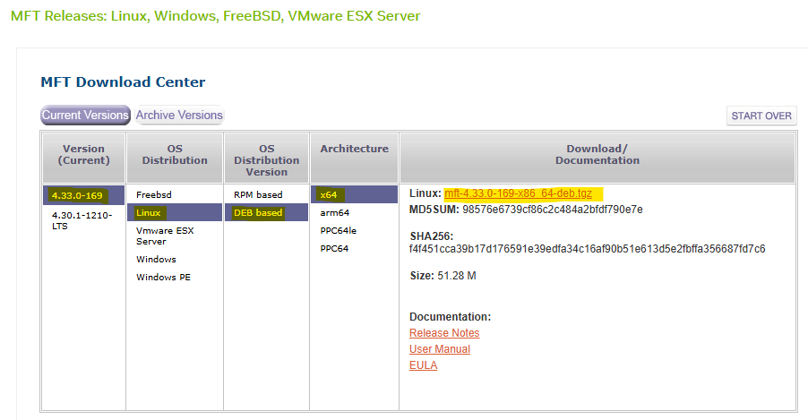
Navigate to the NVIDIA Downloads Site: Open your web browser and go to the official NVIDIA Mellanox software downloads page.
-
Select the Latest Version for your OS:
-
Transfer and Extract MFT Tools on the Worker 1 BareMetal Host.
First Pod Console
root@worker1:~# tar -xvzf /tmp/mft-4.33.0-169-x86_64-deb.tgz -
Navigate into the Extracted Directory.
First Pod Console
root@worker1:~# cd mft-4.33.0-169-x86_64-deb/ -
Run following commands.
First Pod Console
root@worker1:~# apt-get install gcc make dkms root@worker1:~# ./install.sh -
Start MST (Mellanox Software Tools) Service and Identify DPU Device Name.
First Pod Console
root@worker1:~# mst start Starting MST (Mellanox Software Tools) driver set Loading MST PCI module - Success Loading MST PCI configuration module - Success Create devices Unloading MST PCI module (unused) - Success root@worker1:~# mst status MST modules: ------------ MST PCI module is not loaded MST PCI configuration module loaded MST devices: ------------ /dev/mst/mt41692_pciconf0 - PCI configuration cycles access. domain:bus:dev.fn=0000:2b:00.0 addr.reg=88 data.reg=92 cr_bar.gw_offset=-1 Chip revision is: 01 -
Perform Zero-Trust Checking.
First Pod Console
root@worker1:~# mlxprivhost -d 2b:00.0 q
Host configurations
-------------------
level                         : RESTRICTED

Port functions status:
-----------------------
disable_rshim                 : TRUE
disable_tracer                : TRUE
disable_port_owner            : TRUE
disable_counter_rd            : TRUE

#Expected Zero-Trust Output.
This is the most definitive confirmation.
level : RESTRICTEDmeans the host is in Zero-Trust Mode, and theTRUEflags confirm individual security restrictions are active. -
Check Firmware Access with
mlxfwmanager:First Pod Console
root@worker1:~# mlxfwmanager -d 2b:00.0 --query
Querying Mellanox devices firmware ...

Device #1:
----------

  Device Type:      BlueField3
  Part Number:      --
  Description:
  PSID:
  PCI Device Name:  2b:00.0
  Base MAC:         N/A
  Versions:         Current        Available
     FW             --

  Status:           Failed to open device
"Failed to open device" indicates the host is blocked from accessing the DPU for firmware operations, a key aspect of Zero-Trust.
-
Check Device Configuration with
mlxconfig:First Pod Console
root@worker1:~# mlxconfig -d 2b:00.0 q

Device #1:
----------

Device type:        BlueField3
Name:               900-9D3B6-00CV-A_Ax
Description:        NVIDIA BlueField-3 B3220 P-Series FHHL DPU; 200GbE (default mode) / NDR200 IB; Dual-port QSFP112; PCIe Gen5.0 x16 with x16 PCIe extension option; 16 Arm cores; 32GB on-board DDR; integrated BMC; Crypto Enabled
Device:             2b:00.0

Configurations:                                          Next Boot
...
        ALLOW_RD_COUNTERS                           True(1)   # No RO, but restricted by mlxprivhost
...
        PORT_OWNER                                  True(1)   # No RO, but restricted by mlxprivhost
...
        TRACER_ENABLE                               True(1)   # No RO, but restricted by mlxprivhost
Most configuration parameters will be prefixed with
RO(Read-Only). Parameters related to direct host control, likePORT_OWNER,ALLOW_RD_COUNTERS,TRACER_ENABLE, even if shown asTrue(1)for the DPU's internal capability, will be unenforcible by the host due to themlxprivhostrestrictions. The widespreadROstatus shows that the host cannot modify these configurations, reinforcing the DPU's autonomous and secure state. The few parameters withoutROare still overridden by themlxprivhostsecurity policy. -
Check Low-Level Hardware Access with
ethtool:First Pod Console
root@worker1:~# ethtool -d ens1f0np0
Cannot get register dump: Operation not supported
This confirms the DPU is preventing deep, low-level hardware access from the host, aligning with Zero-Trust's isolation goals.
Conclusion
The command outputs of mlxprivhost, mlxfwmanager, mlxconfig (showing RO flags), and ethtool (showing "Operation not supported"), then your NVIDIA BlueField DPU is indeed operating in Zero-Trust Mode.
This means the host has significantly restricted privileges and cannot perform sensitive operations on the DPU, ensuring its security and isolation.
Infrastructure Bandwidth & Latency Validation
Verify the deployment and confirm that the DPU system achieves link-speed performance and low latency by running various tests:
-
Iperf TCP—for bandwidth measurements
-
RDMA—for bandwidth and latency measurements
-
Network isolation
Each test is described in detail. At the end of each test, the achieved performance is displayed.
Notes
Make sure that the servers are tuned for maximum performance (not covered in this document).
Performance and Isolation Tests
Now that the test deployment is running, perform bandwidth and latency performance tests between two bare-metal workload servers.
Ubuntu 24.04 was installed on the servers.
-
Before running the tests, check the Gateway address on each HBN pod:
Jump Node Console
$ ki -n dpf-operator-system get pod -o wide | grep doca-hbn
dpu-cplane-tenant1-doca-hbn-jxkxw-ds-5sbzs                       2/2     Running   0             15m    10.244.0.6     dpu-node-mt2402xz0f9n-mt2402xz0f9n   <none>           <none>
dpu-cplane-tenant1-doca-hbn-jxkxw-ds-ftnpn                       2/2     Running   0             15m    10.244.1.5     dpu-node-mt2402xz0f8g-mt2402xz0f8g   <none>           <none>
dpu-cplane-tenant1-doca-hbn-jxkxw-ds-gjsqq                       2/2     Running   0             16m    10.244.3.4     dpu-node-mt2402xz0f7x-mt2402xz0f7x   <none>           <none>
dpu-cplane-tenant1-doca-hbn-jxkxw-ds-k78vb                       2/2     Running   0             15m    10.244.2.4     dpu-node-mt2402xz0f80-mt2402xz0f80   <none>           <none>


$ ki exec -it -n dpf-operator-system dpu-cplane-tenant1-doca-hbn-jxkxw-ds-gjsqq -- bash
Defaulted container "doca-hbn" out of: doca-hbn, hbn-sidecar, hbn-init (init)

root@dpu-cplane-tenant1-doca-hbn-jxkxw-ds-gjsqq:/tmp# ip a s
...
9: vlan11@br_default: <BROADCAST,MULTICAST,UP,LOWER_UP> mtu 9216 qdisc noqueue master RED state UP group default qlen 1000
    link/ether 0a:ff:4e:3e:99:24 brd ff:ff:ff:ff:ff:ff
    inet 10.0.121.2/29 scope global vlan11
       valid_lft forever preferred_lft forever
    inet6 fe80::8ff:4eff:fe3e:9924/64 scope link
       valid_lft forever preferred_lft forever
...

$ exit

$  ki exec -it -n dpf-operator-system dpu-cplane-tenant1-doca-hbn-jxkxw-ds-k78vb -- bash
Defaulted container "doca-hbn" out of: doca-hbn, hbn-sidecar, hbn-init (init)

root@dpu-cplane-tenant1-doca-hbn-jxkxw-ds-k78vb:/tmp# ip a s
...
9: vlan11@br_default: <BROADCAST,MULTICAST,UP,LOWER_UP> mtu 9216 qdisc noqueue master RED state UP group default qlen 1000
    link/ether 0e:7d:99:41:2e:11 brd ff:ff:ff:ff:ff:ff
    inet 10.0.121.10/29 scope global vlan11
       valid_lft forever preferred_lft forever
    inet6 fe80::c7d:99ff:fe41:2e11/64 scope link
       valid_lft forever preferred_lft forever
...

$ exit
-
Connect to a first Workload Server console, install iperf, perftest, check DPU Hight Speed Interfaces, set route to ethernet and identify the relevant RDMA device:
First Pod Console
root@worker1:~# apt install iperf3 root@worker1:~# apt install perftest root@worker1:~# ip a s ... 6: ens1f0np0: <BROADCAST,MULTICAST> mtu 1500 qdisc noop state DOWN group default qlen 1000 link/ether 58:a2:e1:73:69:e6 brd ff:ff:ff:ff:ff:ff altname enp43s0f0np0 ... root@worker1:~# ip route add 10.0.123.0/22 via 10.0.121.2 depuser@worker2:~$ ping 8.8.8.8 PING 8.8.8.8 (8.8.8.8) 56(84) bytes of data. 64 bytes from 8.8.8.8: icmp_seq=1 ttl=117 time=5.35 ms 64 bytes from 8.8.8.8: icmp_seq=2 ttl=117 time=5.10 ms 64 bytes from 8.8.8.8: icmp_seq=3 ttl=117 time=5.15 ms root@worker1:~# rdma link | grep ens1f0np0 link mlx5_0/1 state DOWN physical_state DISABLED netdev ens1f0np0 -
Configure the
ens1f0np0interface on Ubuntu 24.04 usingiproute2.
Configuration OverviewInterface
IP Address
Default Gateway
ens1f0np0
10.0.121.1/29
10.0.121.2/29
First Pod Console
# Bring up physical interfaces
root@worker1:~# ip link set dev ens1f0np0 up

# Assign IP addresses
root@worker1:~# ip addr add 10.0.121.1/29 dev ens1f0np0

# Set default route
root@worker1:~# ip route add default via 10.0.121.2 dev ens1f0np0
-
Using another console window, reconnect to the jump node and connect to a second Workload Server.
From within the servers, install iperf, perftest, check DPU Hight Speed Interfaces, set route to ethernet and identify the relevant RDMA device:First Pod Console
root@worker2:~# apt install iperf3 root@worker2:~# apt install perftest root@worker2:~# ip a s ... 6: ens1f0np0: <BROADCAST,MULTICAST> mtu 9000 qdisc noop state DOWN group default qlen 1000 link/ether 58:a2:e1:73:6a:58 brd ff:ff:ff:ff:ff:ff altname enp43s0f0np0 ... root@worker2:~# ip route add 10.0.123.0/22 via 10.0.121.10 depuser@worker2:~$ ping 8.8.8.8 PING 8.8.8.8 (8.8.8.8) 56(84) bytes of data. 64 bytes from 8.8.8.8: icmp_seq=1 ttl=117 time=5.35 ms 64 bytes from 8.8.8.8: icmp_seq=2 ttl=117 time=5.10 ms 64 bytes from 8.8.8.8: icmp_seq=3 ttl=117 time=5.15 ms root@worker2:~# rdma link | grep ens1f0np0 link mlx5_0/1 state DOWN physical_state DISABLED netdev ens1f0np0 -
Configure the
ens1f0np0interface on Ubuntu 24.04 usingiproute2.Configuration Overview
Interface
IP Address
Default Gateway
ens1f0np0
10.0.121.9/29
10.0.121.10/29
First Pod Console
# Bring up physical interfaces
root@worker2:~# ip link set dev ens1f0np0 up

# Assign IP addresses
root@worker2:~# ip addr add 10.0.121.9/29 dev ens1f0np0

# Set default route
root@worker2:~# ip route add default via 10.0.121.10 dev ens1f0np0
iPerf TCP Bandwidth Test
Move back to the first server console.
-
Start the
iperf3server side:First BM Server Console
root@worker1:~# iperf3 -s ------------------------------------------------------------ Server listening on TCP port 5001 TCP window size: 128 KByte (default) ------------------------------------------------------------ -
Move to the second server console.
Start theiperfclient side:Second BM Server Console
root@worker2:~#  iperf3 -c 10.0.121.1 -P 16
------------------------------------------------------------
Client connecting to 10.0.121.1, TCP port 5001
TCP window size: 16.0 KByte (default)
------------------------------------------------------------
[  9] local 10.0.121.9 port 48620 connected with 10.0.121.1 port 5001 (icwnd/mss/irtt=14/1448/827)
[ 10] local 10.0.121.9 port 48610 connected with 10.0.121.1 port 5001 (icwnd/mss/irtt=14/1448/881)
[  1] local 10.0.121.9 port 48712 connected with 10.0.121.1 port 5001 (icwnd/mss/irtt=14/1448/608)
[ 14] local 10.0.121.9 port 48728 connected with 10.0.121.1 port 5001 (icwnd/mss/irtt=14/1448/722)
[ 11] local 10.0.121.9 port 48710 connected with 10.0.121.1 port 5001 (icwnd/mss/irtt=14/1448/870)
[  4] local 10.0.121.9 port 48622 connected with 10.0.121.1 port 5001 (icwnd/mss/irtt=14/1448/945)
[  7] local 10.0.121.9 port 48690 connected with 10.0.121.1 port 5001 (icwnd/mss/irtt=14/1448/906)
[ 15] local 10.0.121.9 port 48736 connected with 10.0.121.1 port 5001 (icwnd/mss/irtt=14/1448/689)
[  2] local 10.0.121.9 port 48616 connected with 10.0.121.1 port 5001 (icwnd/mss/irtt=14/1448/796)
[  3] local 10.0.121.9 port 48618 connected with 10.0.121.1 port 5001 (icwnd/mss/irtt=14/1448/940)
[ 12] local 10.0.121.9 port 48706 connected with 10.0.121.1 port 5001 (icwnd/mss/irtt=14/1448/892)
[ 16] local 10.0.121.9 port 48696 connected with 10.0.121.1 port 5001 (icwnd/mss/irtt=14/1448/810)
[  8] local 10.0.121.9 port 48626 connected with 10.0.121.1 port 5001 (icwnd/mss/irtt=14/1448/801)
[  6] local 10.0.121.9 port 48692 connected with 10.0.121.1 port 5001 (icwnd/mss/irtt=14/1448/891)
[  5] local 10.0.121.9 port 48624 connected with 10.0.121.1 port 5001 (icwnd/mss/irtt=14/1448/931)
[ 13] local 10.0.121.9 port 48686 connected with 10.0.121.1 port 5001 (icwnd/mss/irtt=14/1448/903)
[ ID] Interval       Transfer     Bandwidth
[  3] 0.0000-10.0058 sec  14.1 GBytes  12.1 Gbits/sec
[ 13] 0.0000-10.0057 sec  14.2 GBytes  12.2 Gbits/sec
[  7] 0.0000-10.0056 sec  13.4 GBytes  11.5 Gbits/sec
[ 12] 0.0000-10.0057 sec  15.2 GBytes  13.1 Gbits/sec
[  4] 0.0000-10.0058 sec  14.1 GBytes  12.1 Gbits/sec
[ 11] 0.0000-10.0058 sec  15.8 GBytes  13.6 Gbits/sec
[  8] 0.0000-10.0057 sec  13.9 GBytes  11.9 Gbits/sec
[  9] 0.0000-10.0058 sec  13.8 GBytes  11.9 Gbits/sec
[ 15] 0.0000-10.0057 sec  14.3 GBytes  12.3 Gbits/sec
[ 16] 0.0000-10.0058 sec  14.6 GBytes  12.5 Gbits/sec
[  1] 0.0000-10.0057 sec  14.6 GBytes  12.6 Gbits/sec
[  6] 0.0000-10.0058 sec  13.1 GBytes  11.3 Gbits/sec
[ 14] 0.0000-10.0059 sec  13.6 GBytes  11.6 Gbits/sec
[ 10] 0.0000-10.0055 sec  13.5 GBytes  11.6 Gbits/sec
[  2] 0.0000-10.0057 sec  14.0 GBytes  12.0 Gbits/sec
[  5] 0.0000-10.0058 sec  14.6 GBytes  12.6 Gbits/sec
[SUM] 0.0000-10.0010 sec   227 GBytes   195 Gbits/sec
RoCE Latency Test
Return to the first server console.
-
Start the
ib_read_latserver side:First BM Server Console
root@worker1:~# ib_read_lat -F -n 20000 -d mlx5_0 ************************************ * Waiting for client to connect... * ************************************ -
Move to the second server console.
Start theib_read_latclient side:
Second BM Server Console
root@worker2:~# ib_read_lat -F -n 20000 -d mlx5_0 10.0.121.1

---------------------------------------------------------------------------------------
                    RDMA_Read Latency Test
 Dual-port       : OFF          Device         : mlx5_0
 Number of qps   : 1            Transport type : IB
 Connection type : RC           Using SRQ      : OFF
 PCIe relax order: ON
 ibv_wr* API     : ON
 TX depth        : 1
 Mtu             : 1024[B]
 Link type       : Ethernet
 GID index       : 3
 Outstand reads  : 16
 rdma_cm QPs     : OFF
 Data ex. method : Ethernet
---------------------------------------------------------------------------------------
 local address: LID 0000 QPN 0x0048 PSN 0x77ae88 OUT 0x10 RKey 0x186ded VAddr 0x005fe0b3e3a000
 GID: 00:00:00:00:00:00:00:00:00:00:255:255:10:00:121:09
 remote address: LID 0000 QPN 0x0048 PSN 0x51948d OUT 0x10 RKey 0x186ded VAddr 0x00577584a67000
 GID: 00:00:00:00:00:00:00:00:00:00:255:255:10:00:121:01
---------------------------------------------------------------------------------------
 #bytes #iterations    t_min[usec]    t_max[usec]  t_typical[usec]    t_avg[usec]    t_stdev[usec]   99% percentile[usec]   99.9% percentile[usec]
 2       20000          3.98           65.30        4.08               7.89             7.17            31.51                   36.33
---------------------------------------------------------------------------------------
RoCE Bandwidth Test
Return to the first server console.
-
Start the
ib_write_bwserver side:First BM Server Console
root@worker1:~# ib_write_bw -s 1048576 -F -D 30 -q 64 -d mlx5_0 ************************************ * Waiting for client to connect... * ************************************ -
Move to the second server console.
Start theib_write_bwclient side:Second BM Server Console
root@worker2:~# ib_write_bw -s 1048576 -F  -D 30 -q 64 -d mlx5_0 10.0.121.1 --report_gbit
 ---------------------------------------------------------------------------------------
                    RDMA_Write BW Test
 Dual-port       : OFF          Device         : mlx5_0
 Number of qps   : 64           Transport type : IB
 Connection type : RC           Using SRQ      : OFF
 PCIe relax order: ON
 ibv_wr* API     : ON
 TX depth        : 128
 CQ Moderation   : 1
 Mtu             : 1024[B]
 Link type       : Ethernet
 GID index       : 3
 Max inline data : 0[B]
 rdma_cm QPs     : OFF
 Data ex. method : Ethernet
---------------------------------------------------------------------------------------
…
---------------------------------------------------------------------------------------
#bytes     #iterations    BW peak[Gb/sec]    BW average[Gb/sec]   MsgRate[Mpps]
 1048576    420000           0.00               220.72             0.026312
---------------------------------------------------------------------------------------
Network Isolation Test
Finally, verify that the two servers running on different networks—using virtual functions on PF0 and PF0 can't communicate with each other.
Connect to the first workload server, with the PF0 network, and try to ping the PF0 on second node.
-
Run the
pingcommands from PF0 to PF0:First BM Server Console
root@worker1:~# ping -c 3 10.0.121.9 PING 10.0.121.9 (10.0.121.9) 56(84) bytes of data. 64 bytes from 10.0.121.9: icmp_seq=1 ttl=62 time=0.896 ms 64 bytes from 10.0.121.9: icmp_seq=2 ttl=62 time=0.241 ms 64 bytes from 10.0.121.9: icmp_seq=3 ttl=62 time=0.258 ms -
Try to ping the PF0 on nodes 3 and 4. Run the
pingcommands from PF0 to PF0:First BM Server Console
root@worker1:~# ping -c 3 10.0.122.1
PING 10.0.122.1 (10.0.122.1) 56(84) bytes of data.
From 10.0.121.2 icmp_seq=1 Destination Host Unreachable
From 10.0.121.2 icmp_seq=2 Destination Host Unreachable
From 10.0.121.2 icmp_seq=3 Destination Host Unreachable

--- 10.0.122.1 ping statistics ---
3 packets transmitted, 0 received, +3 errors, 100% packet loss, time 2045ms

root@worker1:~# ping -c 3 10.0.122.9
PING 10.0.122.9 (10.0.122.9) 56(84) bytes of data.
From 10.0.121.2 icmp_seq=1 Destination Host Unreachable
From 10.0.121.2 icmp_seq=2 Destination Host Unreachable
From 10.0.121.2 icmp_seq=3 Destination Host Unreachable

--- 10.0.122.9 ping statistics ---
3 packets transmitted, 0 received, +3 errors, 100% packet loss, time 2067ms
This ping operation should fail due to the network isolation implemented in HBN using different VLANs, VNIs and VRFs.
DTS and BlueMan Services Verification
Here's a step-by-step procedure to check the DTS and Blueman DPUServices were deployed on your NVIDIA BlueField DPU.
To be able to log into BlueMan and view the local DTS instance data in a convenient way, the management IP address of the DPU should be entered to a web browser located in the same network as the DPU. In this RDG, it will be demonstrated by using RDP to connect to the Jump node and opening a web browser in it (same as with MaaS, Firewall).
-
To find out the DPU management IP address in the
10.0.110.0/24subnet, obtain the DPU names.Jump Node Console
$ kubectl get dpus -n dpf-operator-system
NAME                                 READY   PHASE   AGE
dpu-node-mt2402xz0f7x-mt2402xz0f7x   True    Ready   150m
dpu-node-mt2402xz0f80-mt2402xz0f80   True    Ready   150m
dpu-node-mt2402xz0f8g-mt2402xz0f8g   True    Ready   150m
dpu-node-mt2402xz0f9n-mt2402xz0f9n   True    Ready   150m
dpu-node-mt2511600r8p-mt2511600r8p   True    Ready   70m
dpu-node-mt2511600rc3-mt2511600rc3   True    Ready   70m
dpu-node-mt2511600rp1-mt2511600rp1   True    Ready   70m
dpu-node-mt2511600ruh-mt2511600ruh   True    Ready   70m
-
Obtain the DPU management IP:
Jump Node Console
$ $ kubectl get dpus -n dpf-operator-system -o json \ | jq -r ' .items[] | "\(.metadata.name)\t\(.status.addresses[].address)" ' dpu-node-mt2402xz0f7x-mt2402xz0f7x 10.0.110.211 dpu-node-mt2402xz0f7x-mt2402xz0f7x dpu-node-mt2402xz0f7x-mt2402xz0f7x dpu-node-mt2402xz0f80-mt2402xz0f80 10.0.110.212 dpu-node-mt2402xz0f80-mt2402xz0f80 dpu-node-mt2402xz0f80-mt2402xz0f80 dpu-node-mt2402xz0f8g-mt2402xz0f8g 10.0.110.214 dpu-node-mt2402xz0f8g-mt2402xz0f8g dpu-node-mt2402xz0f8g-mt2402xz0f8g dpu-node-mt2402xz0f9n-mt2402xz0f9n 10.0.110.213 dpu-node-mt2402xz0f9n-mt2402xz0f9n dpu-node-mt2402xz0f9n-mt2402xz0f9n dpu-node-mt2511600r8p-mt2511600r8p 10.0.110.217 dpu-node-mt2511600r8p-mt2511600r8p dpu-node-mt2511600r8p-mt2511600r8p dpu-node-mt2511600rc3-mt2511600rc3 10.0.110.215 dpu-node-mt2511600rc3-mt2511600rc3 dpu-node-mt2511600rc3-mt2511600rc3 dpu-node-mt2511600rp1-mt2511600rp1 10.0.110.218 dpu-node-mt2511600rp1-mt2511600rp1 dpu-node-mt2511600rp1-mt2511600rp1 dpu-node-mt2511600ruh-mt2511600ruh 10.0.110.216 dpu-node-mt2511600ruh-mt2511600ruh dpu-node-mt2511600ruh-mt2511600ruh -
In the RDP session, open a web browser and enter https://<DPU_INTERNAL_IP>. A warning of self-signed certificate should appear; click accept the risk and proceed.
Afterwards it will open the login page: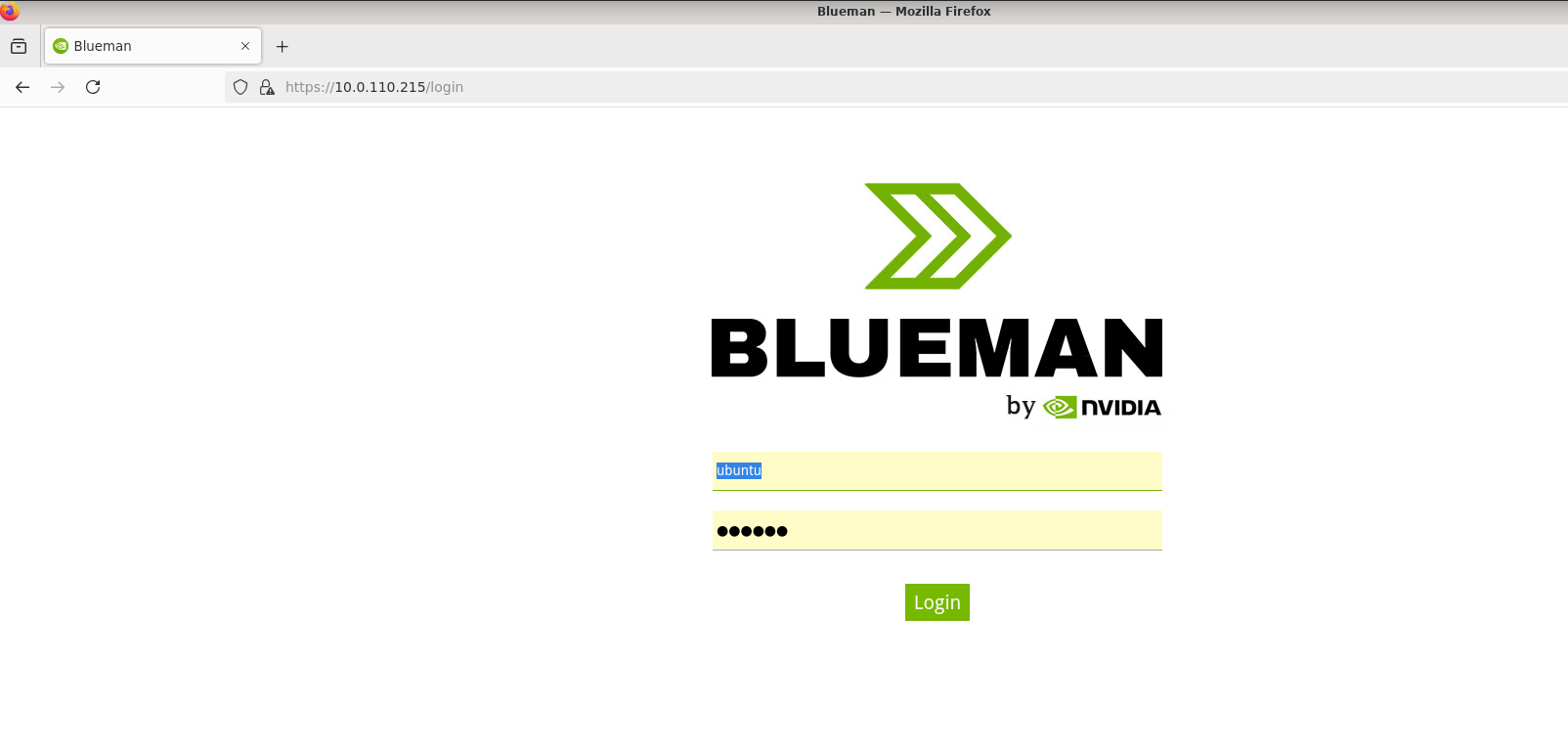
The login credentials to use are the same pair used for the SSH connection to the DPU (ubuntu/ubuntu). However, login straight away won't work and an additional certificate exception in the browser has to be made. -
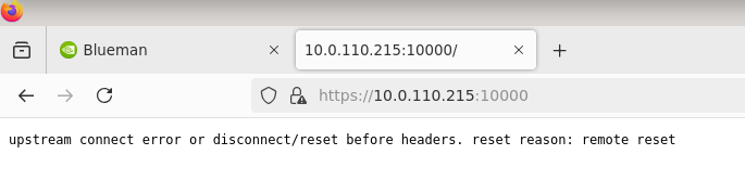
Open another tab in the browser and enter https://<DPU_INTERNAL_IP>:10000. It will again prompt a warning of self-signed certificate; click accept the risk to add it to your browser exception list. An error message similar to the following will be displayed, but it doesn't matter since it's an internal address to fetch resources from–in other words, the error message can be ignored.
-
Return to the BlueMan login page, enter the credentials, and you should be able to login.
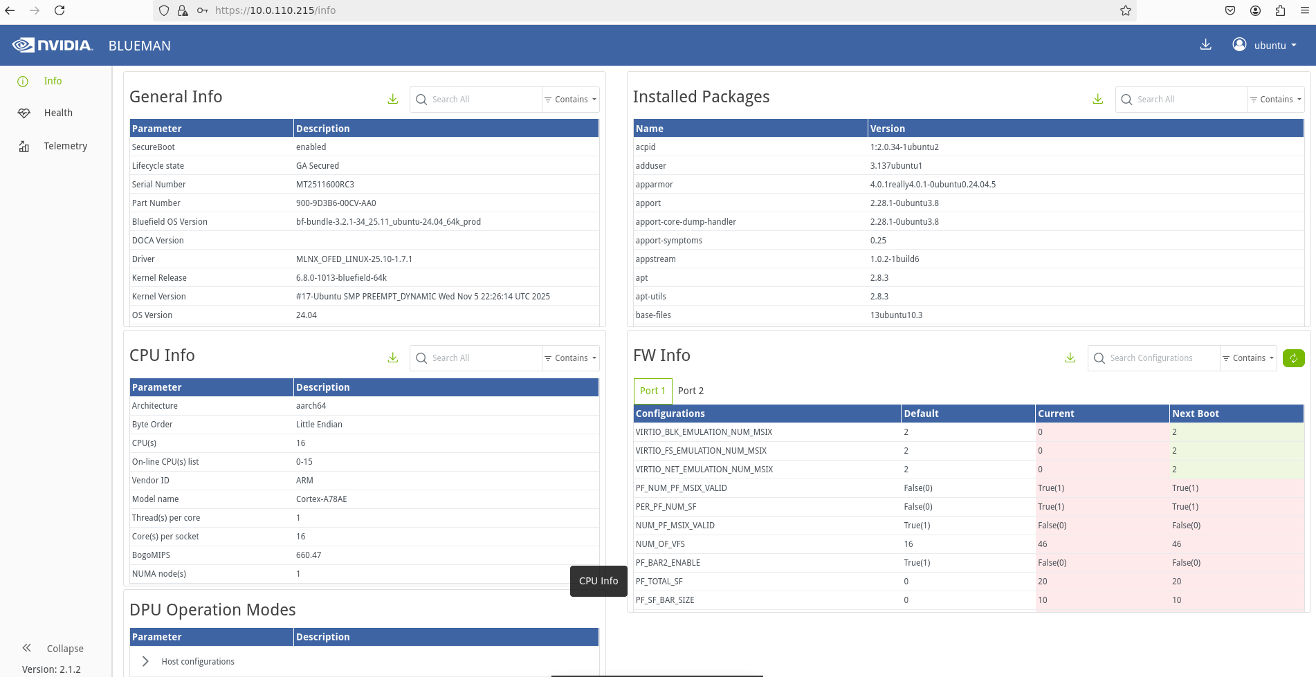
Done.
Authors
|
|
Boris Kovalev
Boris Kovalev has worked for the past several years as a Solutions Architect, focusing on NVIDIA Networking/Mellanox technology, and is responsible for complex machine learning, Big Data and advanced VMware-based cloud research and design. Boris previously spent more than 20 years as a senior consultant and solutions architect at multiple companies, most recently at VMware. He has written multiple reference designs covering VMware, machine learning, Kubernetes, and container solutions which are available at the NVIDIA Documents website. |

NVIDIA, the NVIDIA logo, and BlueField are trademarks and/or registered trademarks of NVIDIA Corporation in the U.S. and other countries. Other company and product names may be trademarks of the respective companies with which they are associated.™
2025 NVIDIA Corporation. All rights reserved.©
Last updated: