

Created on Apr 3, 2021 by Boris Kovalev
Updated on May 26, 2022 by Boris Kovalev
On This Page
Scope
This document describes how to configure VMware vSAN over RoCE in VMware vSphere 7.0 Update 3d over NVIDIA® end-to-end 100 Gb/s Ethernet solution.
Abbreviations and Acronyms
|
Term |
Definition |
|---|---|
|
DAC |
Direct Attached Cable |
|
DHCP |
Dynamic Host Configuration Protocol |
|
NOS |
Network Operation System |
|
NVMe |
Non-Volatile Memory express |
|
PVRDMA |
Paravirtual RDMA |
|
RDMA |
Remote Direct Memory Access |
|
RoCE |
RDMA over Converged Ethernet |
|
SDS |
Software-Defined Storage |
|
vDS |
vSphere Distributed Switch |
|
VM |
Virtual Machine |
Introduction
Hybrid cloud has become the dominant architecture for enterprises seeking to extend their compute capabilities by using public clouds while maintaining on-premises clusters that are fully interoperable with their cloud service providers.
To meet demands, provide services and allocate resources efficiently, enterprise IT teams have deployed hyperconverged architectures that use the same servers for compute and storage. These architectures include three core technologies: software-defined-compute (or server virtualization), software-defined-networking and software-defined storage (SDS). Taken together, these enable a software-defined data center. Also widely adopted: high-performance Ethernet for server-to-server and server-to-storage communication.
vSAN is VMware’s enterprise storage solution for SDS that supports hyperconverged infrastructure systems and is fully integrated with VMware vSphere as a distributed layer of software within the ESXi hypervisor. vSAN eliminates the need for external shared storage and simplifies storage configuration through storage policy-based management. Deploying virtual machine storage policies, users can define storage requirements and capabilities.
vSAN aggregates local, direct-attached storage devices to create and share a single storage pool across all hosts in the hyperconverged cluster, utilizing faster flash SSD for cache and inexpensive HDD to maximize capacity.
RDMA (Remote Direct Memory Access) is an innovative technology that boosts data communication performance and efficiency. RDMA makes data transfers more efficient and enables fast data movement between servers and storage without using the OS or burdening the server’s CPU. Throughput is increased, latency reduced and the CPU is freed to run applications.
RDMA technology is already widely used for efficient data transfer in render farms and large cloud deployments, such as HPC (including machine/deep learning), NVMe-oF and iSER-based storage, NFSoRDMA, mission-critical SQL databases such as Oracle’s RAC (Exadata), IBM DB2 pureScale, Microsoft SQL solutions and Teradata.
For the last several years, VMware has been adding RDMA support to ESXi, including PVRDMA (paravirtual RDMA) to accelerate data transfers between virtual servers and iSER and NVMe-oF for remote storage acceleration.
VMware’s vSANoRDMA is now fully qualified and available as of the ESXi 7.0 U3d release, making it ready for deployments.
This document provides instructions on how to configure vSAN over RoCE Datastores located on local NVMe disks in VMware vSphere 7.0 U3d over NVIDIA end-to-end 100 Gb/s Ethernet solution.
HCI Bench v2.6.1 VDBENCH will be used for benchmarks to show performance improvements between vSAN over RDMA and TCP protocols by using the same hardware.
References
-
What is RDMA?
-
RDMA over Converged Ethernet (RoCE)
-
ConnectX® Ethernet Driver for VMware® ESXi Server
-
VMware vSAN 7 Design guide
-
vSAN Network Design
-
HCIBench | VMware Flings
Solution Architecture
Key Components and Technologies
-
vSAN over RoCE Support for VMware
vSAN over RDMA provides increased performance for vSAN.
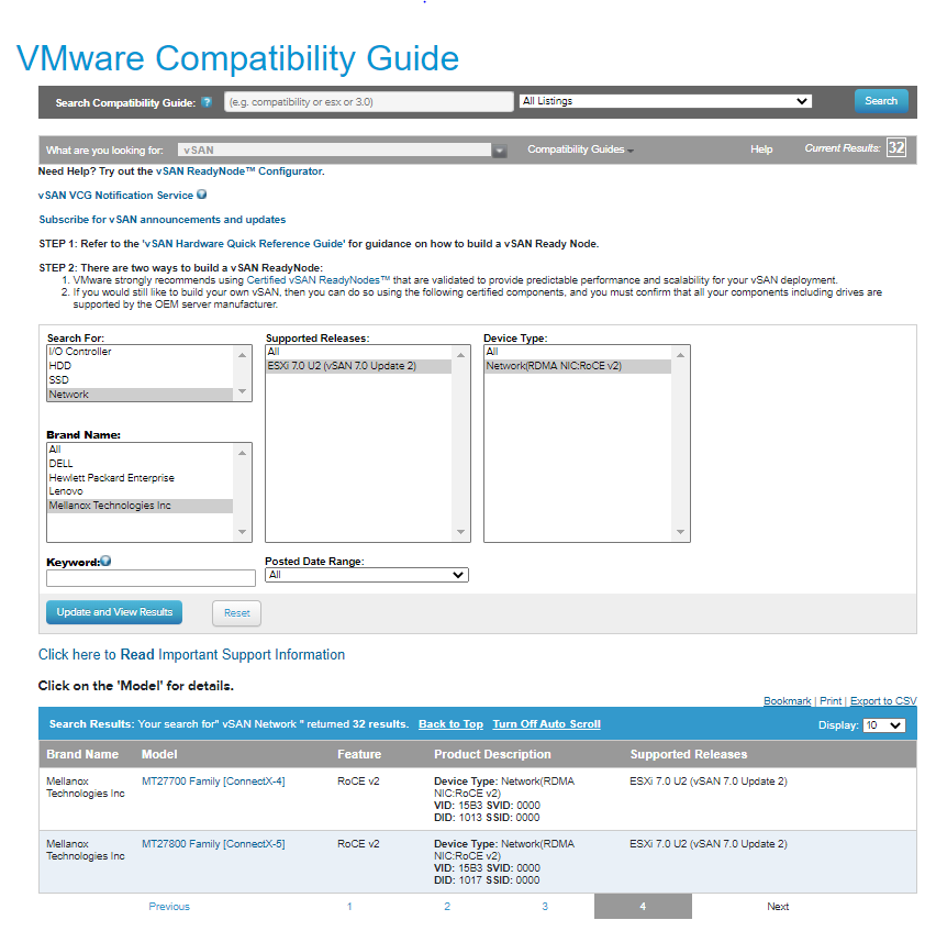
Each vSAN host must have a vSAN certified RDMA-capable NIC, as listed in the vSAN section of the VMware Compatibility Guide. Use only the same model network adapters from the same vendor on each end of the connection.
All hosts in the cluster must support RDMA. If any host loses RDMA support, the entire vSAN cluster switches to TCP.
vSAN with RDMA supports NIC failover, but does not support LACP or IP-hash-based NIC teaming.
- NVIDIA Cumulus Linux
NVIDIA® Cumulus® Linux is the industry's most innovative open network operating system that allows you to automate, customize, and scale your data center network like no other.
-
NVIDIA ConnectX SmartNICs
10/25/40/50/100/200 and 400G Ethernet Network Adapters
The industry-leading NVIDIA® ConnectX® family of smart network interface cards (SmartNICs) offer advanced hardware offloads and accelerations.
NVIDIA Ethernet adapters enable the highest ROI and lowest Total Cost of Ownership for hyperscale, public and private clouds, storage, machine learning, AI, big data, and telco platforms.
- NVIDIA Spectrum Ethernet Switches
Flexible form-factors with 16 to 128 physical ports, supporting 1GbE through 400GbE speeds.
Based on a ground-breaking silicon technology optimized for performance and scalability, NVIDIA Spectrum switches are ideal for building high-performance, cost-effective, and efficient Cloud Data Center Networks, Ethernet Storage Fabric, and Deep Learning Interconnects.
NVIDIA combines the benefits of NVIDIA Spectrum™ switches, based on an industry-leading application-specific integrated circuit (ASIC) technology, with a wide variety of modern network operating system choices, including NVIDIA Cumulus® Linux, SONiC and NVIDIA Onyx®.
-
NVIDIA LinkX Cables
The NVIDIA® LinkX® product family of cables and transceivers provides the industry’s most complete line of 10, 25, 40, 50, 100, 200, and 400GbE in Ethernet and 100, 200 and 400Gb/s InfiniBand products for Cloud, HPC, hyperscale, Enterprise, telco, storage and artificial intelligence, data center applications.
Logical Design
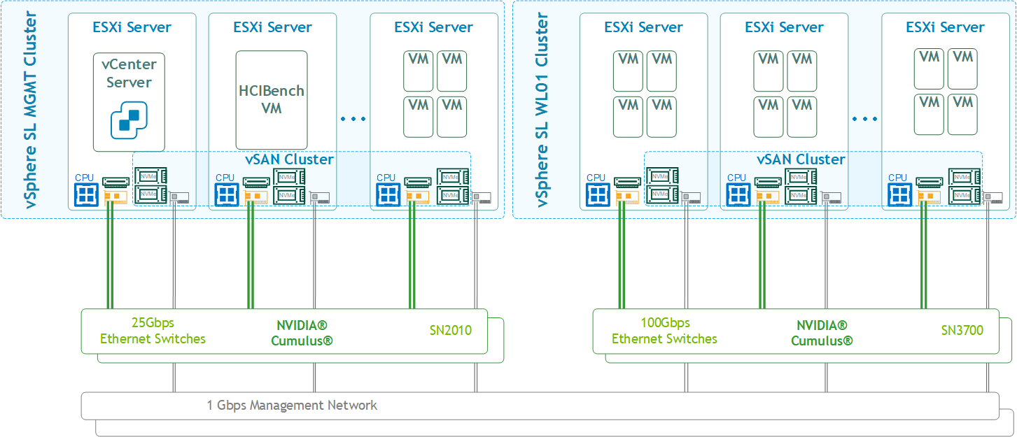
Software Stack Components
This guide assumes the following software and drivers are installed:
-
VMware ESXi 7.0.3d, build 19482537
-
VMware vCenter 7.0.3, build 19234570
-
Distributed Switch 7.0.3
-
NVIDIA® ConnectX® Driver for VMware ESXi Server v4.21.71.101
-
NVIDIA® ConnectX®-6DX FW version 22.32.2004
-
NVIDIA® ConnectX®-6LX FW version 26.32.1010
-
Network Operational System (NOS): NVIDIA Cumulus™ v5.1
-
HCIBench version 2.6.1
Bill of Materials
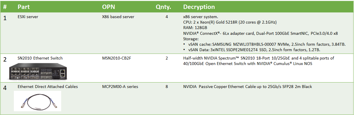
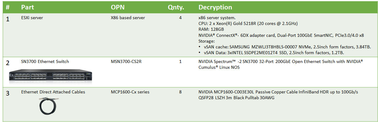
The following hardware setup is utilized in the vSphere environment described in this guide.
Management Cluster:
Workload Cluster:
Deployment and Configuration
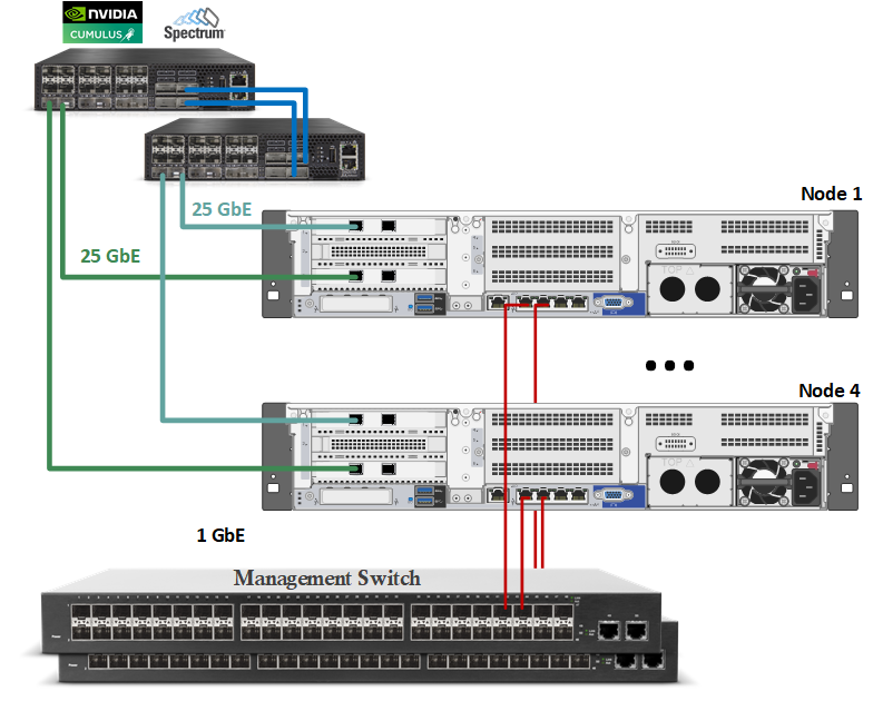
Wiring
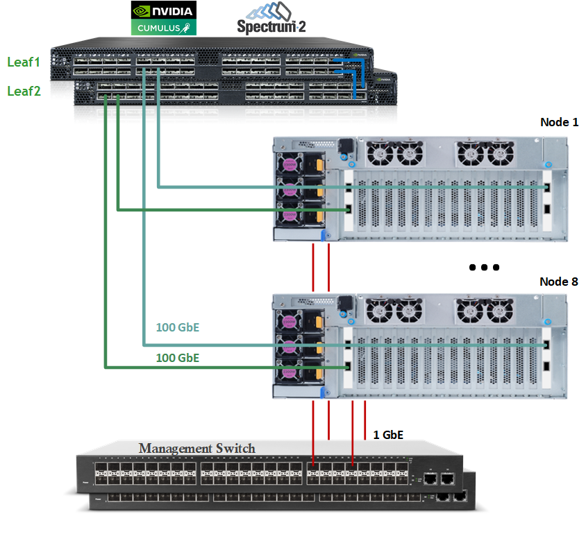
This document covers highly available VMware vSphere cluster deployment.
Management Cluster:
Workload Cluster:
Network
Prerequisites
-
Switch OS
NVIDIA Cumulus 5.1 -
Network adapter
2x ConnectX-6 Dx or LX
Latest FW and Driver Versions. For more information, please see:
How-to: Firmware update for NVIDIA ConnectX-4/5 adapter on VMware ESXi 6.5 and above
How-to: NVIDIA driver upgrade on VMware ESXi 6.5 and above -
vSAN over RDMA
vSAN RDMA Ready network adapter is required and can be found on the vSAN VCG.
-
Management Network
DHCP and DNS services are required. The components installation and configuration are not covered in this guide
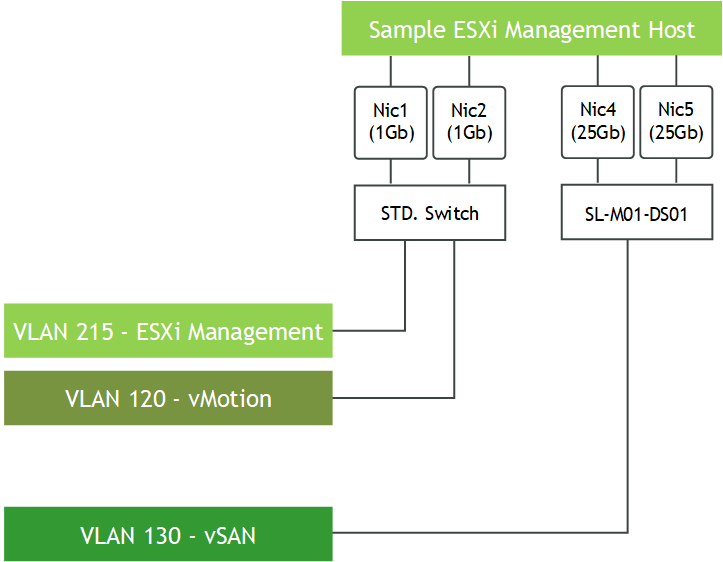
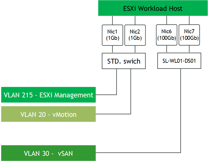
vSphere Switches design
Management Cluster Host
Workload Cluster Host
Hosts Network Configuration
This table provides details of the ESXi server, switches and storage system names and their network configuration.
The one distributed port group (DPG per cluster (vSAN-VLAN1630-DPG, vSAN-VLAN30-DPG)) is required to support Active/Passive vSAN connectivity.
SL MGMT Cluster
|
Server |
Server Name |
IP and NICs |
|
|---|---|---|---|
|
High-Speed Ethernet Network |
Management Network 10.7.215.0/24 |
||
|
SL MGMT Cluster |
|||
|
ESXi-01 |
clx-host-51 |
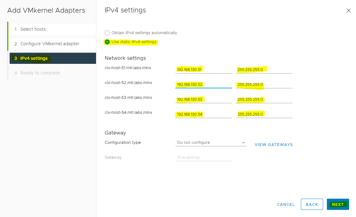
vmk1: 192.168.120.51 (vMotion) vmk2: 192.168.130.51 (vSAN) |
vmk0: 10.7.215.51 From DHCP (reserved) |
|
ESXi-02 |
clx-host-52 |
vmk1: 192.168.120.52 (vMotion) vmk2: 192.168.130.52 (vSAN) |
vmk0: 10.7.215.52 From DHCP (reserved) |
|
ESXi-03 |
clx-host-53 |
vmk1: 192.168.120.53(vMotion) vmk2: 192.168.130.53 (vSAN) |
vmk0: 10.7.215.53 From DHCP (reserved) |
|
ESXi-04 |
clx-host-54 |
vmk1: 192.168.120.54(vMotion) vmk2: 192.168.130.54 (vSAN) |
vmk0: 10.7.215.54 From DHCP (reserved) |
|
Leaf-01 |
clx-swx-033 |
|
10.7.215.233 |
|
Leaf-02 |
clx-swx-034 |
|
10.7.215.234 |
SL WL01 Cluster
|
Server |
Server Name |
IP and NICs |
|
|---|---|---|---|
|
High-Speed Ethernet Network |
Management Network 10.7.215.0/24 |
||
|
ESXi-05 |
clx-host-069 |
vmk1: 192.168.20.169 (vMotion) vmk2: 192.168.30.169 (vSAN) |
vmk0: 10.7.215.169 From DHCP (reserved) |
|
ESXi-06 |
clx-host-070 |
vmk1: 192.168.20.170 (vMotion) vmk2: 192.168.30.170 (vSAN) |
vmk0: 10.7.215.170 From DHCP (reserved) |
|
ESXi-07 |
clx-host-071 |
vmk1: 192.168.20.171 (vMotion) vmk2: 192.168.30.171 (vSAN) |
vmk0: 10.7.215.171 From DHCP (reserved) |
|
ESXi-08 |
clx-host-072 |
vmk1: 192.168.20.172 (vMotion) vmk2: 192.168.30.172 (vSAN) |
vmk0: 10.7.215.172 From DHCP (reserved) |
|
ESXi-09 |
clx-host-073 |
vmk1: 192.168.20.173 (vMotion) vmk2: 192.168.30.173 (vSAN) |
vmk0: 10.7.215.173 From DHCP (reserved) |
|
ESXi-010 |
clx-host-074 |
vmk1: 192.168.20.174 (vMotion) vmk2: 192.168.30.174 (vSAN) |
vmk0: 10.7.215.174 From DHCP (reserved) |
|
ESXi-11 |
clx-host-075 |
vmk1: 192.168.20.175 (vMotion) vmk2: 192.168.30.175 (vSAN) |
vmk0: 10.7.215.175 From DHCP (reserved) |
|
ESXi-12 |
clx-host-076 |
vmk1: 192.168.20.176 (vMotion) vmk2: 192.168.30.176 (vSAN) |
vmk0: 10.7.215.176 From DHCP (reserved) |
|
Leaf-03 |
clx-swx-035 |
|
10.7.215.37 |
|
Leaf-04 |
clx-swx-036 |
|
10.7.215.38 |
Network Switch Configuration
Port channel and VLAN configuration
Run the following commands on both Leaf switches in the Management Cluster to configure port channel and VLAN.
nv set interface bond1 type bond
nv set interface bond1 bond member swp21-22
nv set interface bond1 bridge domain br_default
nv set bridge domain br_default vlan 1630
nv set bridge domain br_default vlan 100
nv set interface bond1 bridge domain br_default vlan all 1630
nv set interface bond1 bridge domain br_default untagged 100
nv set interface bond1 bridge domain br_default vlan all add 1620
nv config apply
nv config save
Run the following commands on both Leaf switches in the Workload Cluster to configure port channel and VLAN.
nv set interface bond1 type bond
nv set interface bond1 bond member swp31-32
nv set interface bond1 bridge domain br_default
nv set bridge domain br_default vlan 215
nv set bridge domain br_default vlan 20
nv set bridge domain br_default vlan 30
nv set interface bond1 bridge domain br_default untagged 215
nv set interface bond1 bridge domain br_default vlan all 20
nv set interface bond1 bridge domain br_default vlan all 30
nv config apply
nv config save
Enable RDMA over Converged Ethernet Lossless (with PFC and ETS)
RoCE transport is utilized to accelerate vSAN networking. To get the highest possible results, the network is configured to be lossless.
Run the following commands on all Leaf switches to configure a lossless networks for NVIDIA Cumulus.
nv set qos roce
nv config apply
nv config save
To Check RoCE configuration, run the following command:
$sudo nv show qos roce

                    operational  applied   description
------------------  -----------  --------  ------------------------------------------------------
enable                           on        Turn the feature 'on' or 'off'.  The default is 'off'.
mode                lossless     lossless  Roce Mode
cable-length        100          100       Cable Length(in meters) for Roce Lossless Config
congestion-control
  congestion-mode   ECN                    Congestion config mode
  enabled-tc        0,3                    Congestion config enabled Traffic Class
  max-threshold     1.43 MB                Congestion config max-threshold
  min-threshold     146.48 KB              Congestion config min-threshold
pfc
  pfc-priority      3                      switch-prio on which PFC is enabled
  rx-enabled        enabled                PFC Rx Enabled status
  tx-enabled        enabled                PFC Tx Enabled status
trust
  trust-mode        pcp,dscp               Trust Setting on the port for packet classification


RoCE PCP/DSCP->SP mapping configurations
===========================================
        pcp  dscp                     switch-prio
    --  ---  -----------------------  -----------
    0   0    0,1,2,3,4,5,6,7          0
    1   1    8,9,10,11,12,13,14,15    1
    2   2    16,17,18,19,20,21,22,23  2
    3   3    24,25,26,27,28,29,30,31  3
    4   4    32,33,34,35,36,37,38,39  4
    5   5    40,41,42,43,44,45,46,47  5
    6   6    48,49,50,51,52,53,54,55  6
    7   7    56,57,58,59,60,61,62,63  7


RoCE SP->TC mapping and ETS configurations
=============================================
        switch-prio  traffic-class  scheduler-weight
    --  -----------  -------------  ----------------
    0   0            0              DWRR-50%
    1   1            0              DWRR-50%
    2   2            0              DWRR-50%
    3   3            3              DWRR-50%
    4   4            0              DWRR-50%
    5   5            0              DWRR-50%
    6   6            6              strict-priority
    7   7            0              DWRR-50%


RoCE pool config
===================
        name                   mode     size   switch-priorities  traffic-class
    --  ---------------------  -------  -----  -----------------  -------------
    0   lossy-default-ingress  Dynamic  50.0%  0,1,2,4,5,6,7      -
    1   roce-reserved-ingress  Dynamic  50.0%  3                  -
    2   lossy-default-egress   Dynamic  50.0%  -                  0,6
    3   roce-reserved-egress   Dynamic  inf    -                  3


Exception List
=================
        description
vSAN Cluster Creation
VMware vSAN Requirements
There are many considerations to be made from a requirements perspective when provisioning a VMware vSAN software-defined storage solution.
Please refer to the official VMware vSAN 7 Design guide, chapter 2 "Requirements for Enabling vSAN".
vSAN with RDMA Requirements
vSAN 7.0 Update 2 and above supports RDMA communication. To use it:
-
Each vSAN host must have a vSAN certified RDMA-capable NIC, as listed in the vSAN section of the VMware Compatibility Guide
-
Only the same model network adapters from the same vendor can be used on each end of the connection
-
All hosts in the cluster must support RDMA. If any host loses RDMA support, the entire vSAN cluster switches to TCP
Preparing vSphere Cluster for vSAN
Prerequisites
-
Physical server configuration
All ESXi servers must have the same PCIe placement for the NIC and expose the same interface name. -
vSphere cluster with minimum 3 VMware vSphere ESXi 7.0.3d or above hosts
-
vCenter 7.0.3d or above
-
Installer privileges: The installation requires administrator privileges on the target machine
-
Connection to ESXi host management interface
-
High speed network connectivity
-
Verify that in your environment NTP configured and works properly.
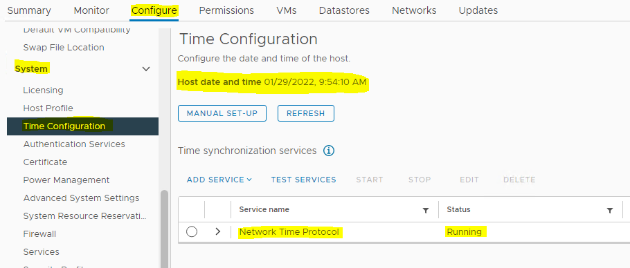
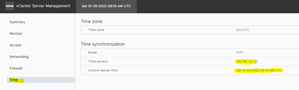
To create a vSAN cluster, create a vSphere host cluster and enable vSAN on the cluster.
Installation of vCenter, ESXi hosts, and configuration vSphere cluster are beyond the scope of this document.
To enable the exchange of data in the vSAN cluster, you must provide a VMkernel network adapter for vSAN traffic on each ESXi host.
Firstly, make sure to create a vSphere Distributed Switch (vDS) with a distributed port group on a vSphere cluster with one Active and Standby uplinks.
vSAN with RDMA supports NIC failover, but does not support LACP or IP-hash-based NIC teaming.
Creating a Distributed Switch for vSAN Traffic
To create a new vDS:
-
Launch the vSphere Web Client and connect to a vCenter Server instance.

-
On the vSphere Web Client home screen, select the vCenter object from the list on the left.
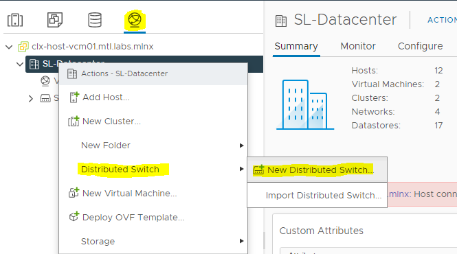
Hover over the Distributed Switches from the Inventory Lists area, then click New Distributed Switch (see image below) to launch the New vDS creation wizard:
-
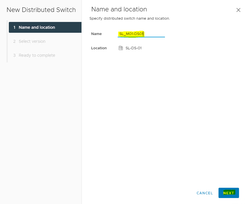
Provide a name for the new distributed switch and select the location within the vCenter inventory where you would like to store the new vDS (a data center object or a folder).
Click NEXT.
-
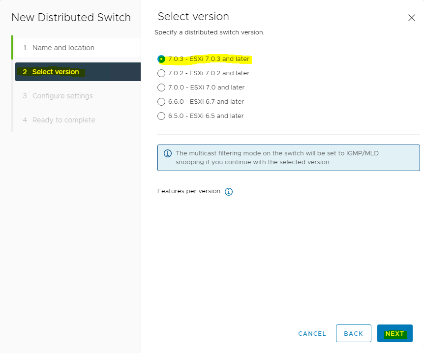
Select the version of the vDS to create.
Click NEXT.
-
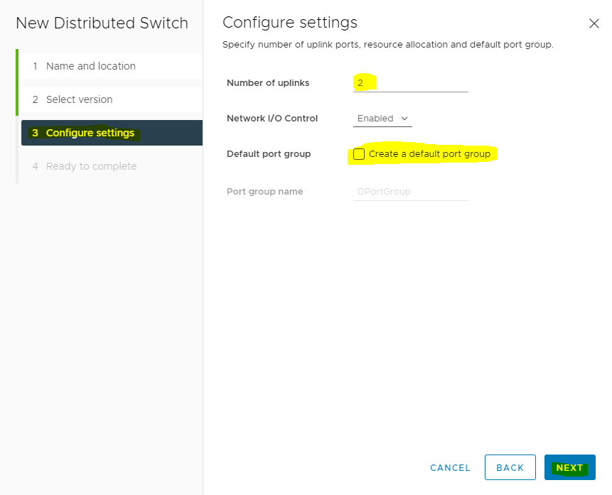
Specify the number of uplink ports as 2, uncheck the Create a default port group box and enter a name to that group.
Click NEXT.
-
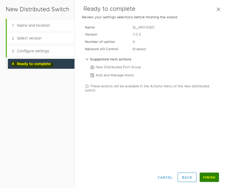
Click Finish.
-
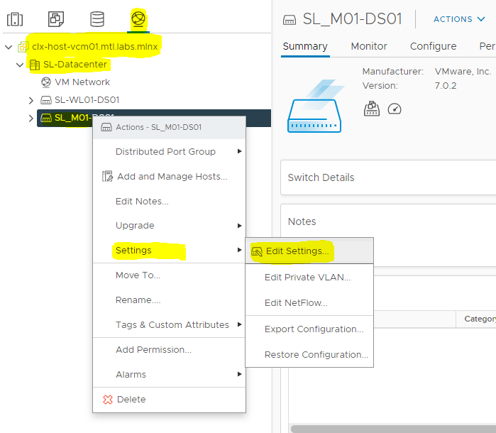
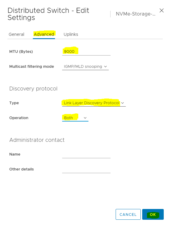
Set the MTU for the newly created distributed switch.
Right-click the new distributed switch in the list of objects and select Settings → Edit Settings... from the Actions menu.
-
In the Storage-DSwitch-Edit Settings dialog box, set the MTU to 9000, Discovery protocol to Link Layer Discovery Protocol and Operation to Both.
Click OK.
Adding Hosts to vDS
To add an ESXi host to an existing vDS:
-
Launch the vSphere Web Client, and connect to a vCenter Server instance.
-
Navigate to the list of Hosts in the SL MGMT cluster and select ESXi host.
-
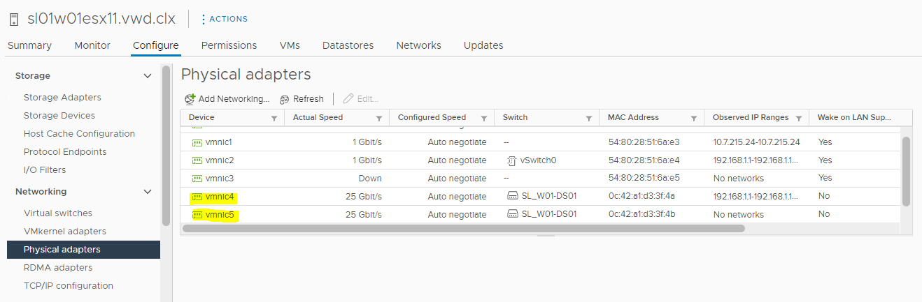
Select Configure → Networking → Physical adapters.
-
Check the network ports that you are going to use. In this case, vmnic4 and vmnic5 are used.
-
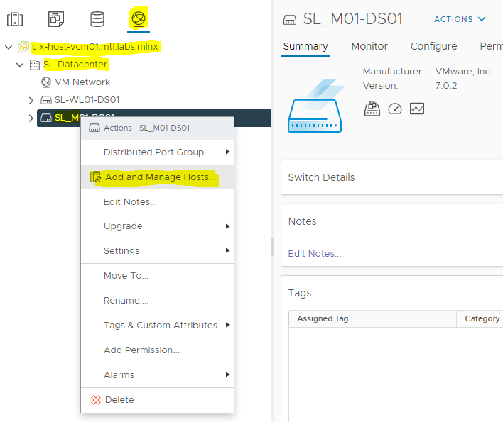
Navigate to the list of distributed switches.
-
Right-click the new distributed switch in the list of objects and select Add and Manage Hosts from the Actions menu.
-
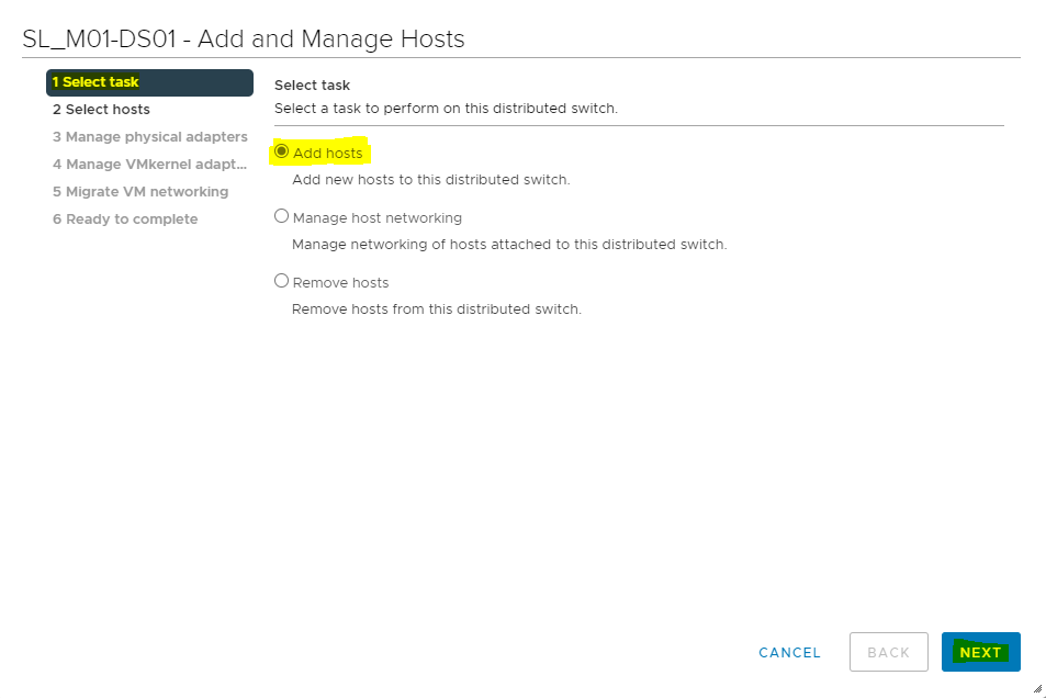
Select the Add hosts button and click NEXT.
-
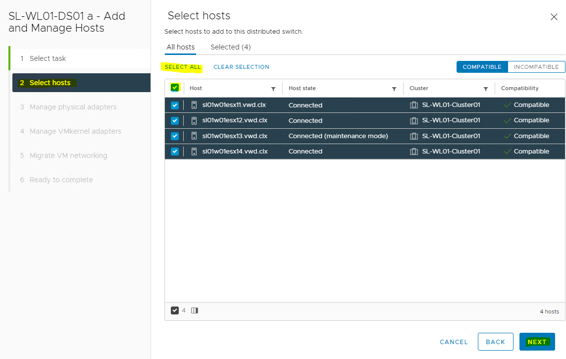
From the list of the new hosts, check the boxes with the names of each ESXi host you would like to add to the VDS.
Click NEXT.
-
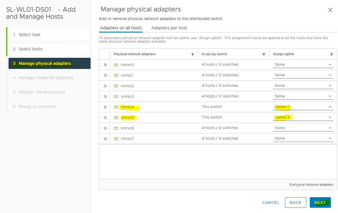
In the next Manage physical adapters menu click on Adapters on all hosts and configure vmnic4 and vmnic5 (Sample) in an ESXi host as Uplink 1 and Uplink 2 for the VDS.
-
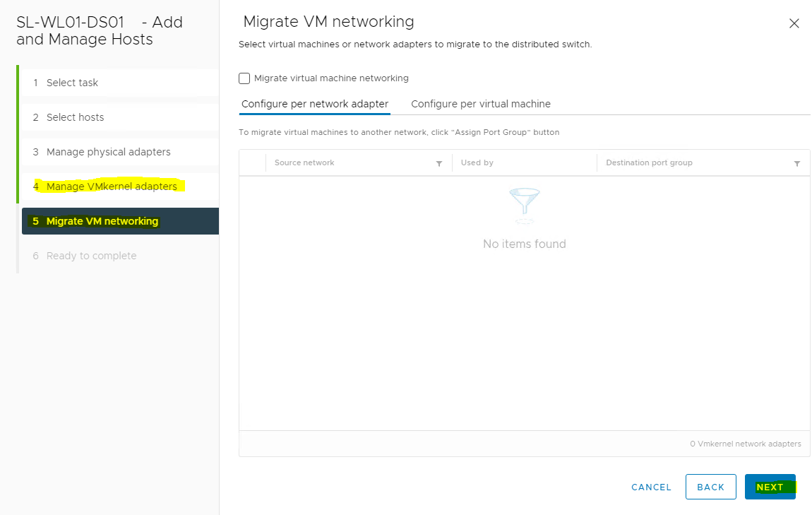
In the next Manage VMkernel adapters and Migrate VM networking menus, click NEXT to continue.
-
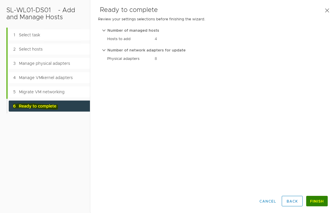
Click FINISH.
-
Repeat the Distributed Switch for vSAN Traffic steps for Workload cluster.
Creating Distributed Port Groups for Storage Traffic
This section lists the steps required to create two distributed port groups with one Active and one Standby uplinks.
-
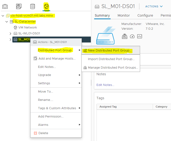
Add VMkernel Adapters for Distributed Port Groups by right-clicking on Distributed switch, and select Distributed Port Group>New Distributed Port Group.
-
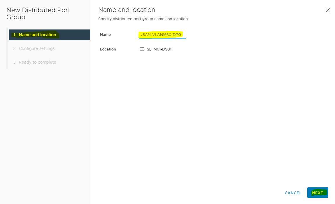
On the New Distributed Port Group dialog box, enter Name as <vSAN-VLAN1630-DPG> and click NEXT.
-
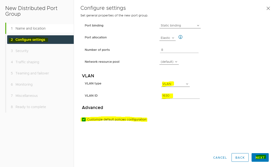
Select VLAN type as VLAN, set the VLAN ID to your VLAN (sample 1630), and check the Customize default policies configuration checkbox, and click NEXT.
-
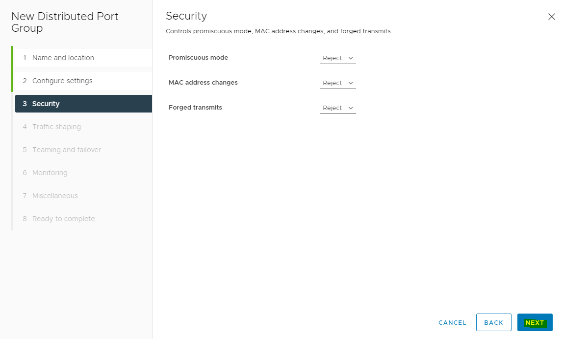
On the Security dialog box, click NEXT.
-
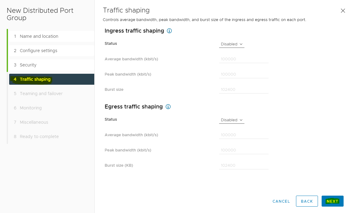
On the Traffic shaping dialog box, click NEXT.
-
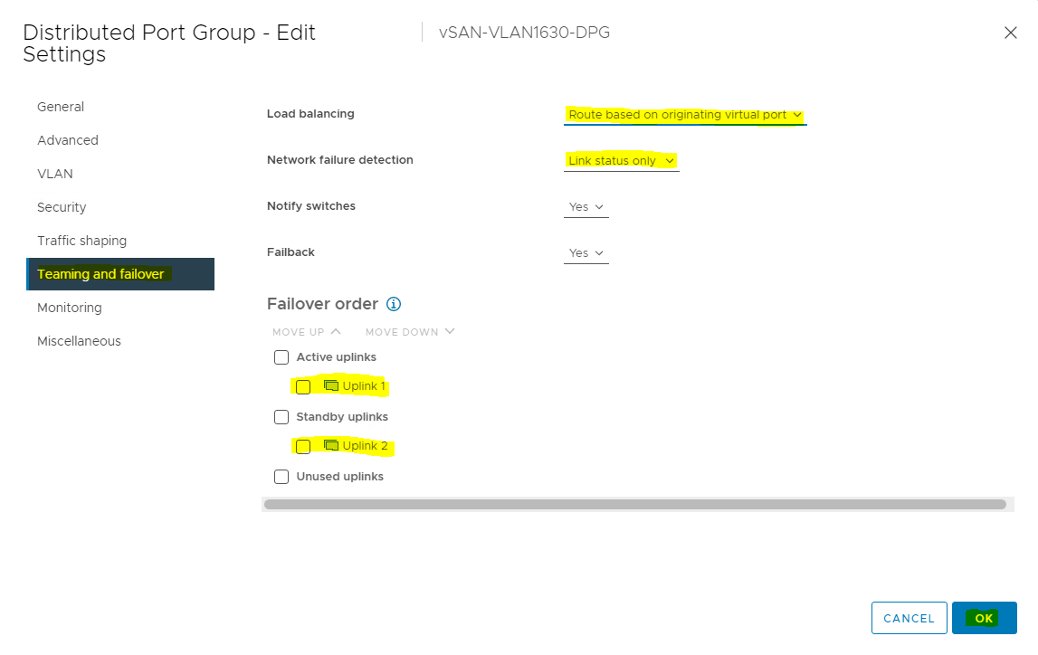
NIC Teaming with RDMA
RDMA for vSAN supports the following teaming policies for virtual switches.
• Route-based on originating virtual port
• Route-based on source MAC hash
• Use explicit failover order
-
In the Teaming and failover dialog box, select Uplink 1 as active uplink and set Uplink 2 to standby uplink. Click NEXT.
-
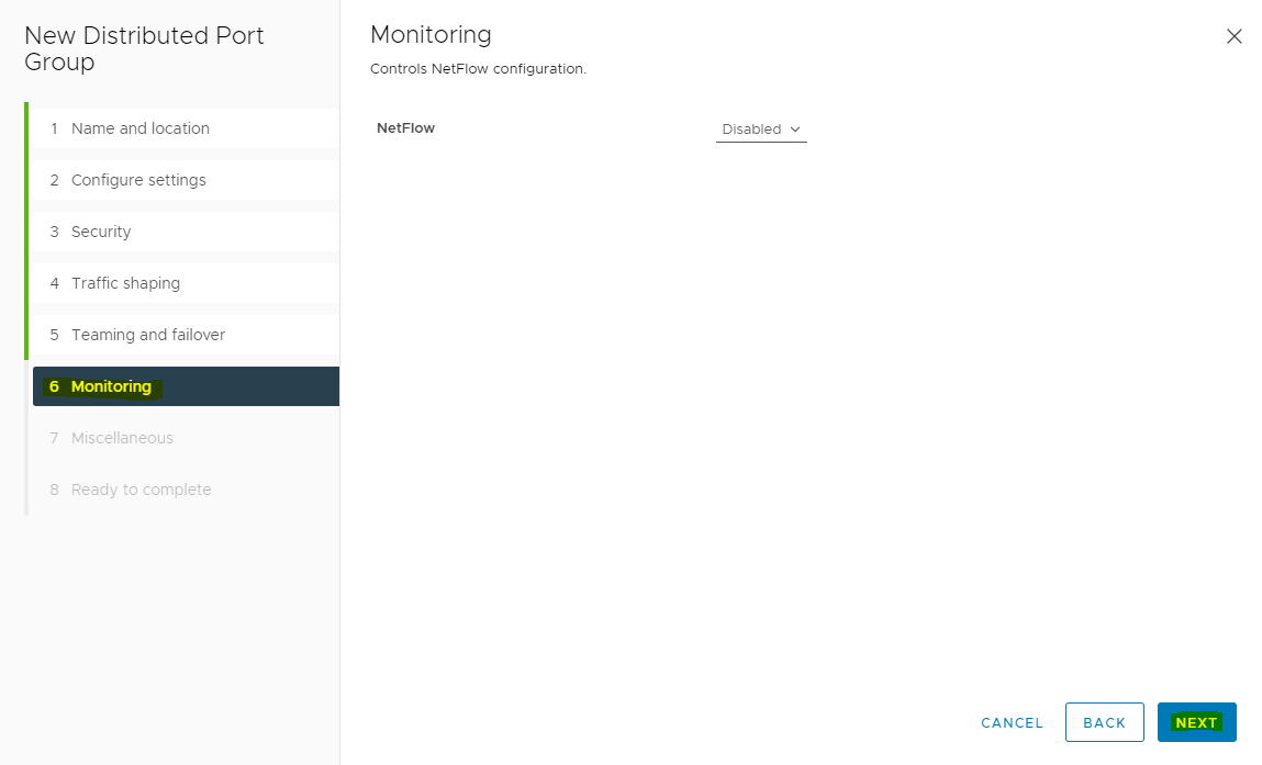
In the Monitoring dialog box, set NetFlow to Disabled, and click NEXT.
-
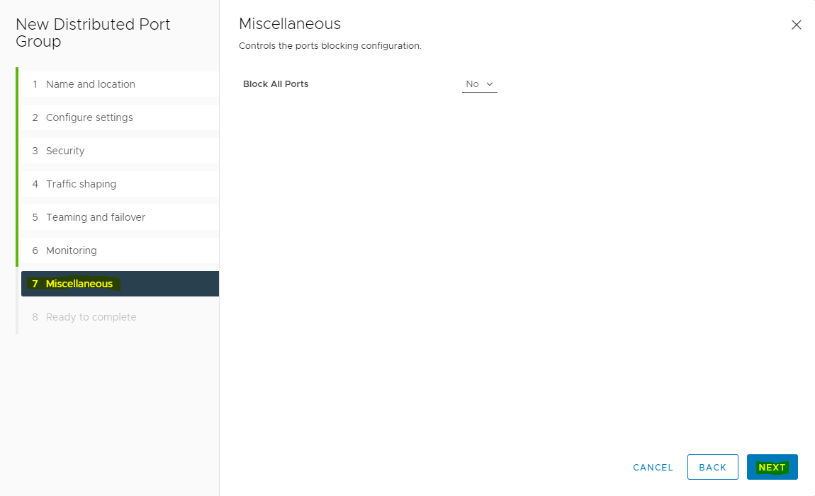
In the Miscellaneous dialog box, set Block All Ports to No, and click NEXT.
-
In the Ready to complete dialog box, review all the changes before you click FINSIH.
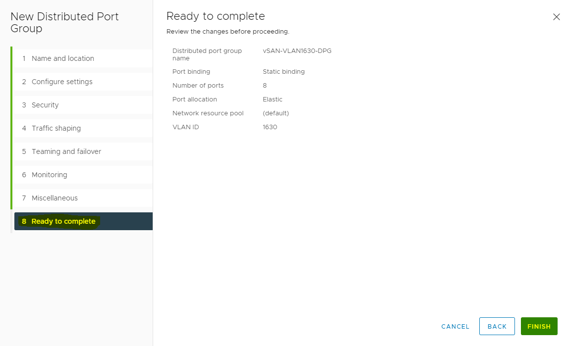
Adding a VMkernel Network for vSAN
To add VMkernel adapters for distributed port groups, follow the steps below.
-
Right click the distributed port group and select Add VMkernel Adapters.
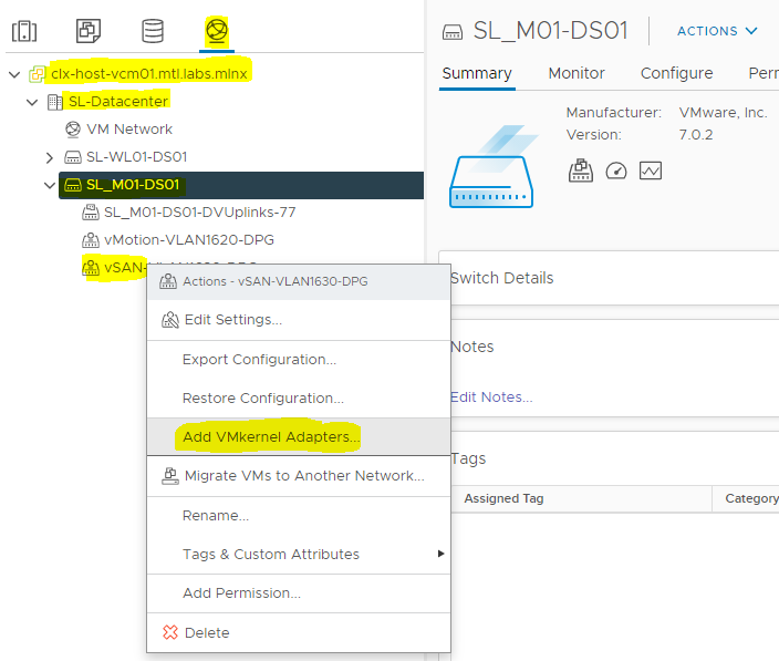
-
Click Attached Hosts...
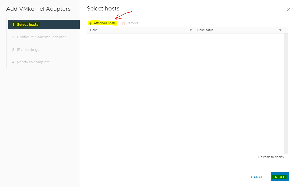
-
Select the hosts and click OK.
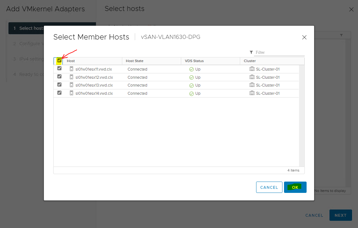
-
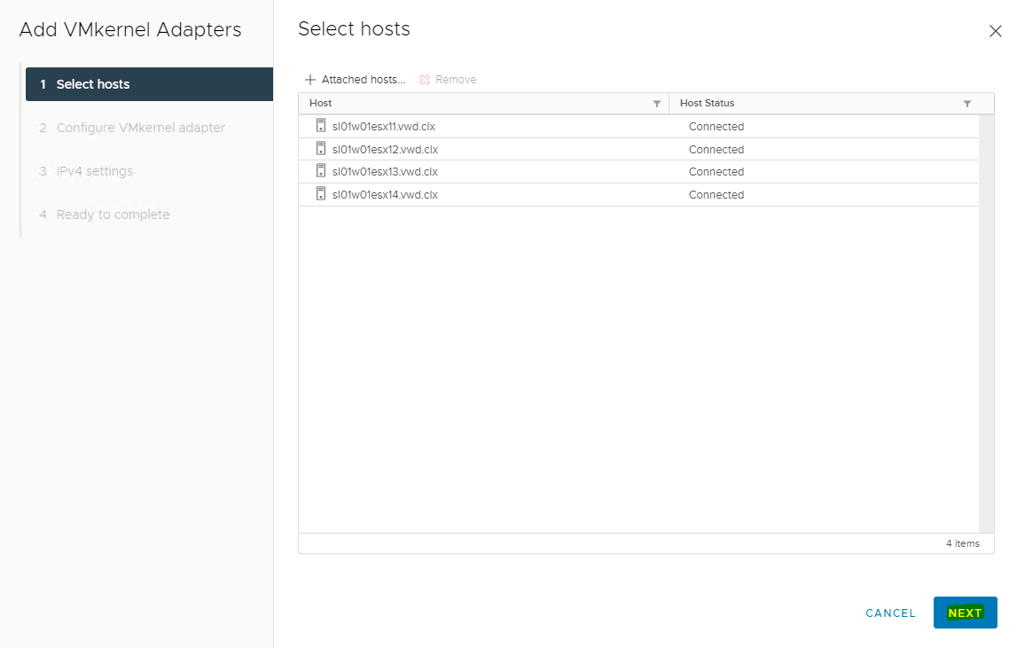
Click NEXT in the Select hosts dialog box.
-
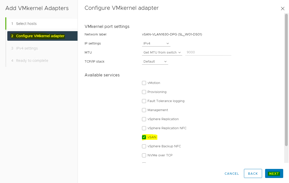
Select vSAN(sample) in Available services, and click NEXT.
-
Enter the Network Settings and Gateway details, and click NEXT.
-
Click FINISH.
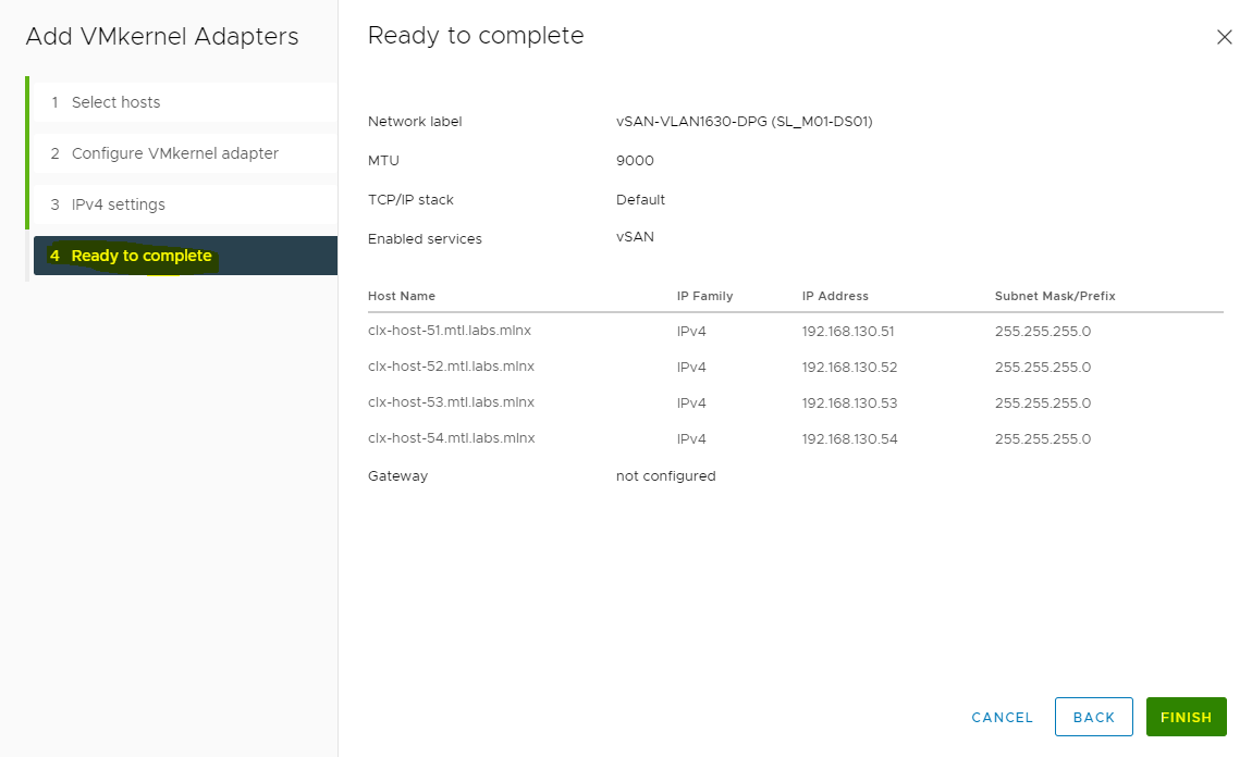
Once the ESXi Cluster Networking configuration is complete, it can be verified under the Distributed Switch>Configure>Topology tab.
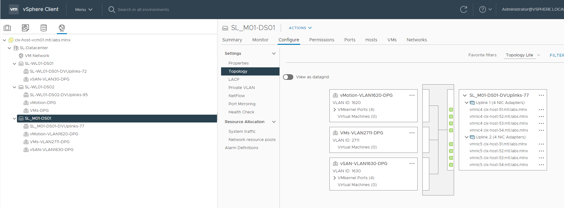
vSAN network is enabled for the host.
Manually Enabling vSAN
Use the HTML5-based vSphere Client to configure your vSAN cluster.
You can use Quickstart to quickly create and configure a vSAN cluster. For more information, please see Using Quickstart to Configure and Expand a vSAN Cluster.
To enable and configure vSAN, follow the steps below.
-
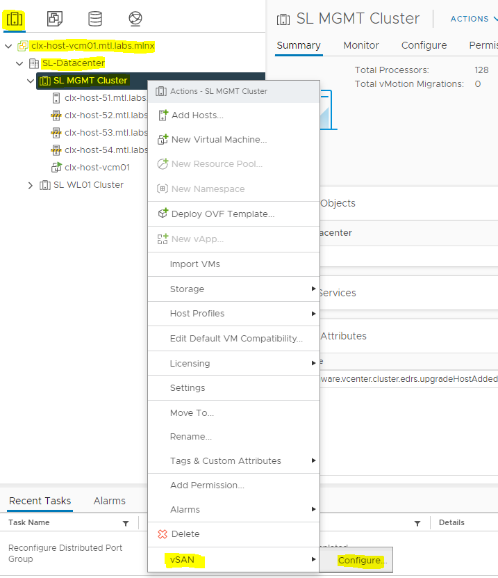
Navigate to an existing host cluster. Sample SL MGMT Cluster.
-
Right click the cluster and select vSAN → Configure... from the Actions menu.
-
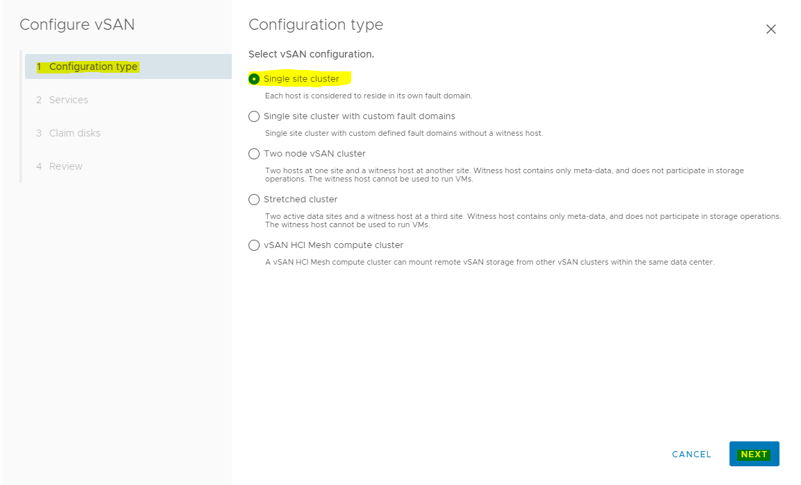
Select the Single site cluster type of vSAN cluster to configure, and click Next.
-
Single site cluster - see vSAN Deployment Options
-
Single site cluster with custom fault domains - see "Managing Fault Domains in vSAN Clusters" in Administering VMware vSAN
-
Two node vSAN cluster - see vSAN Deployment Options
-
Stretched cluster - see Introduction to Stretched Clusters
-
vSAN HCI Mesh compute cluster - see "Sharing Remote Datastores with HCI Mesh" in Administering VMware vSAN
-
-
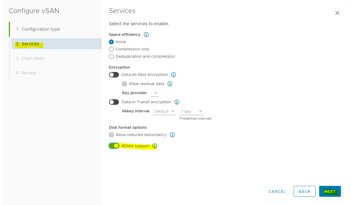
Configure the vSAN services to use, and click NEXT.
-
Configure the data management features, including deduplication and compression, data-at-rest encryption, data-in-transit encryption and RDMA support.
For more details, see Edit vSAN Settings.
-
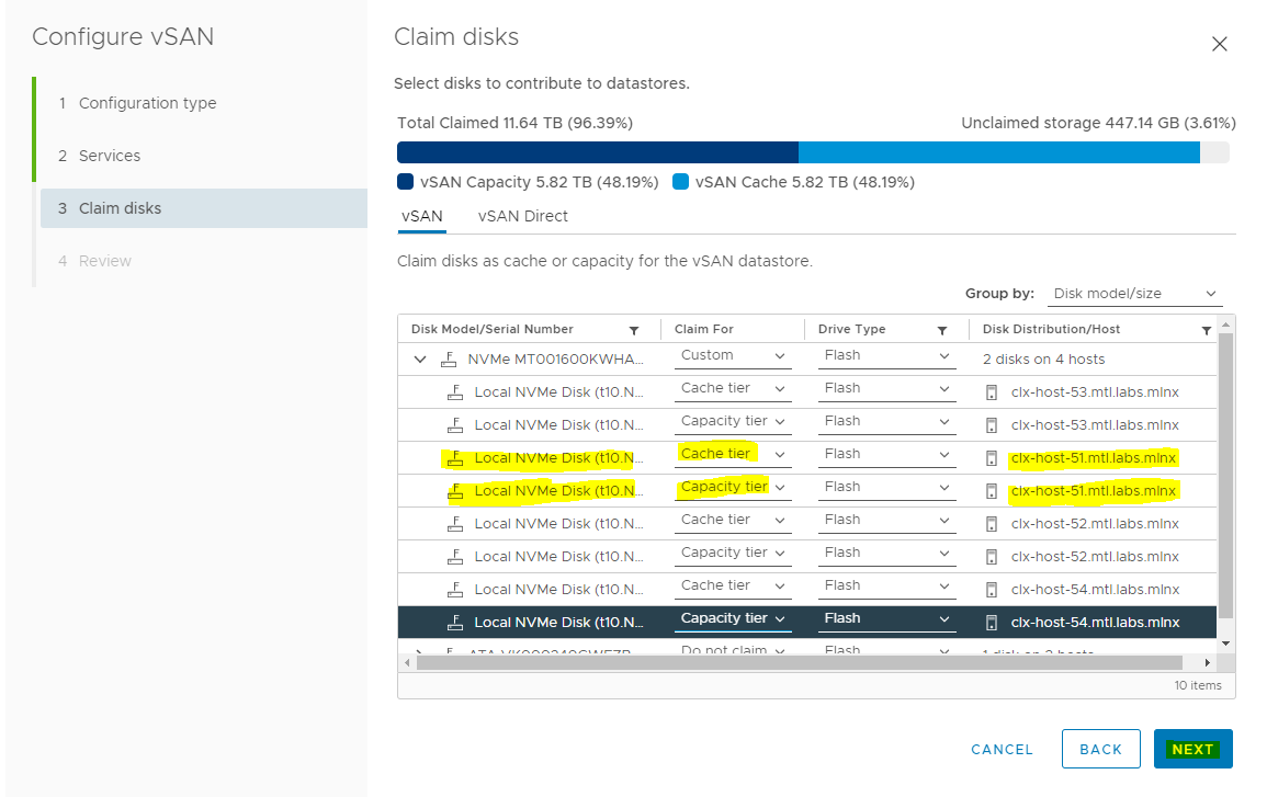
Claim disks for the vSAN cluster, and click Next.
Each host requires at least one flash device in the cache tier, and one or more devices in the capacity tier.
For more details, see "Managing Disk Groups and Devices" in Administering VMware vSAN.
-
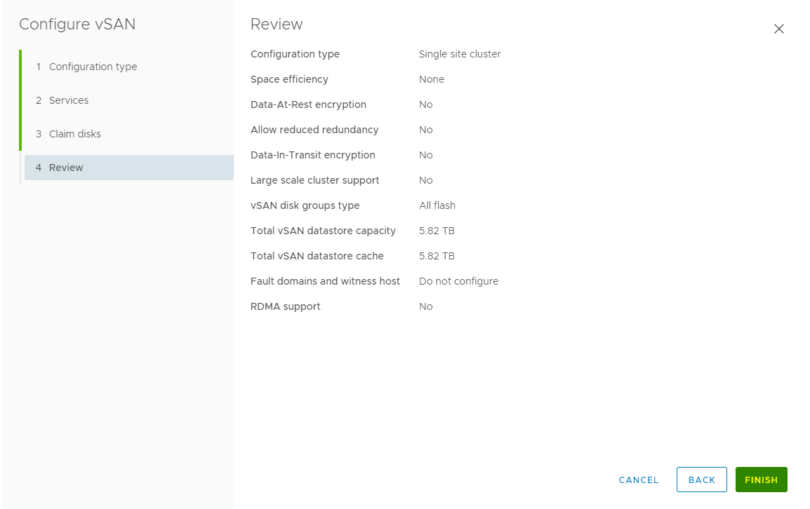
Review the configuration, and click FINISH.
Configure License Settings for a vSAN Cluster
You must assign a license to a vSAN cluster before its evaluation period or its currently assigned license expire.
Some advanced features, such as all-flash configuration and stretched clusters, require a license that supports the feature.
Prerequisites
-
To view and manage vSAN licenses, you must have the Global.Licenses privilege enabled on the vCenter Server systems.
To assign a license to a vSAN cluster, follow the steps below.
-
Navigate to your vSAN cluster.
-
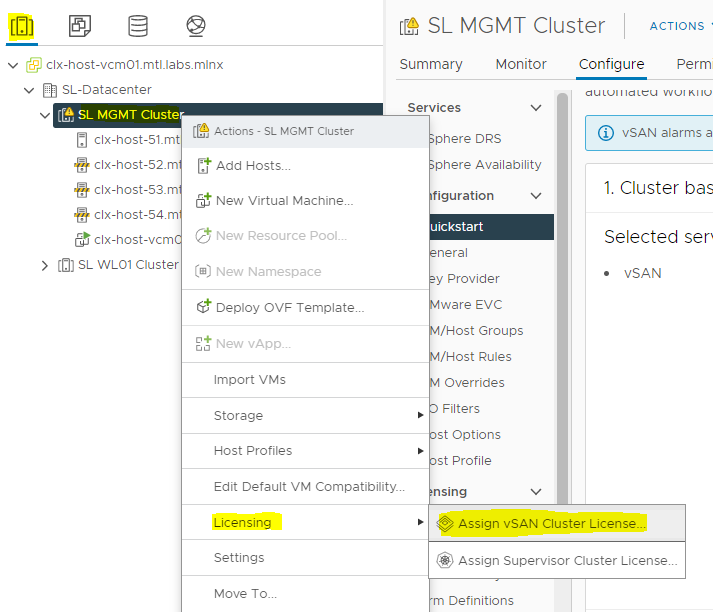
Right click the cluster and select Licensing → Assign vSAN Cluster License... from the Actions menu.
-
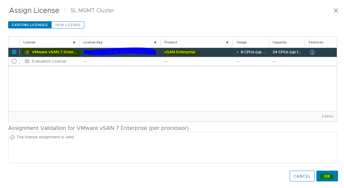
Select an existing license and click OK.
-
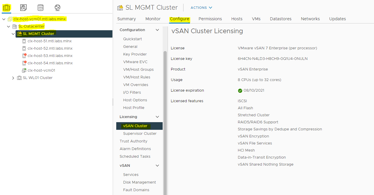
Validate the Assigned License by:
-
Navigating to your vSAN cluster.
-
Clicking the Configure tab.
-
Selecting vSAN Cluster under Licensing.
-
-
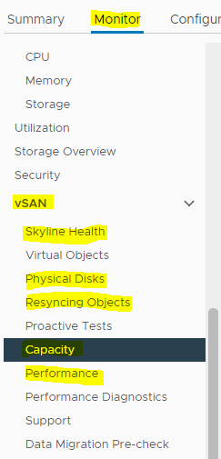
After you enable vSAN, a single datastore is created.
You can review the Skyline Health, Physical Disks, Resyncing Objects, Capacity and Performance.
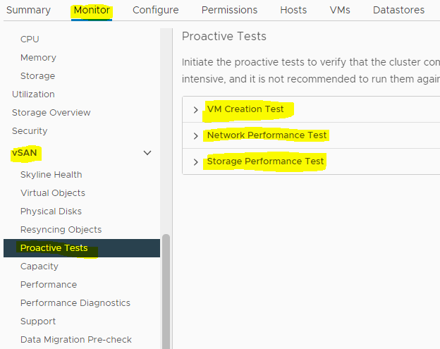
In addition, you can run Proactive Tests of the vSAN datastore.
Done!
Appendix
Test the Environment
Hardware and Software Components
Host under test:
• Server, with 2 x Gigabyte SYS-2028U-TN24R4T+ host, with 2 x Intel(R) Xeon(R) CPU E5-2660 v4 @ (28 cores @ 2.00GHz each), 128GB of RAM
• Dual-port NVIDIA ConnectX®-6DX Adapter Card, with the driver 4.21.71.1-1OEM.702.0.0.17473468 and FW 22.33.1048 versions
• VMware ESXi™ 7.0 Update 3, 19898904
Network:
• NVIDIA Spectrum® SN3700 Open Ethernet Switch
NVIDIA® Cumulus® Linux v5.1 Network OS
• NVIDIA MCP1600-C003E30L Passive Copper Cable InfiniBand HDR up to 100Gb/s QSFP28 LSZH 3m Black Pulltab 30AWG
Virtual Machine and Benchmark Configuration
We used HCI Bench v2.6.1 FIO benchmark workloads to measure performance with following parameter configurations:
|
HCIBench |
|
|
Benchmarking Tool |
FIO |
|
Number of VMs |
24 |
|
VM's Number of CPU |
4 |
|
VM's Number of Data Disk |
8 |
|
VM's Size of RAM in GB |
8 |
|
VM's Size of Data Disk in GiB |
14 |
|
Number of Disks to Test |
8 |
|
Working-Set Percentage |
100 |
|
Number of Threads Per Disk |
4 |
|
Random Percentage |
100 |
Performance Results
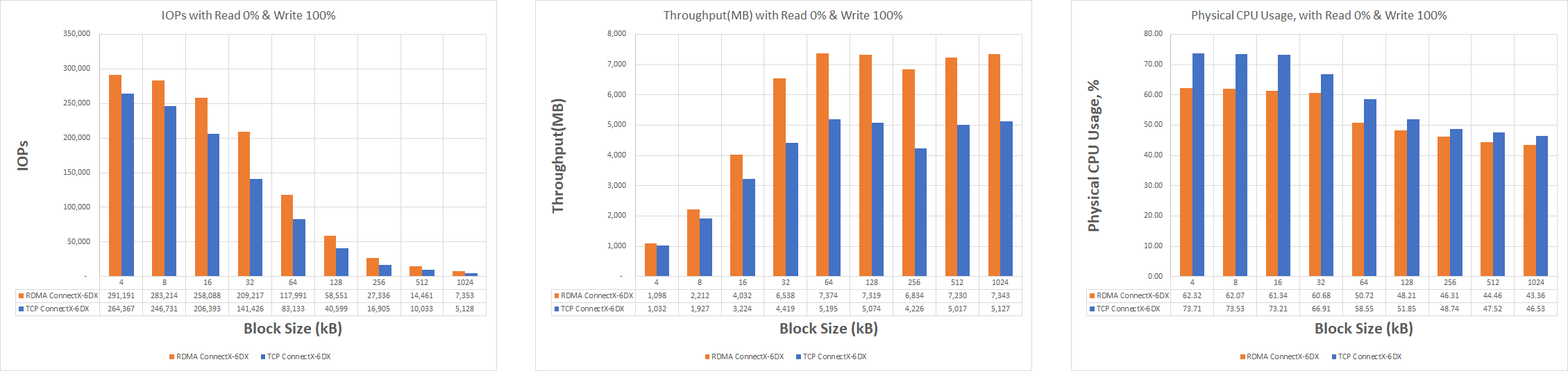
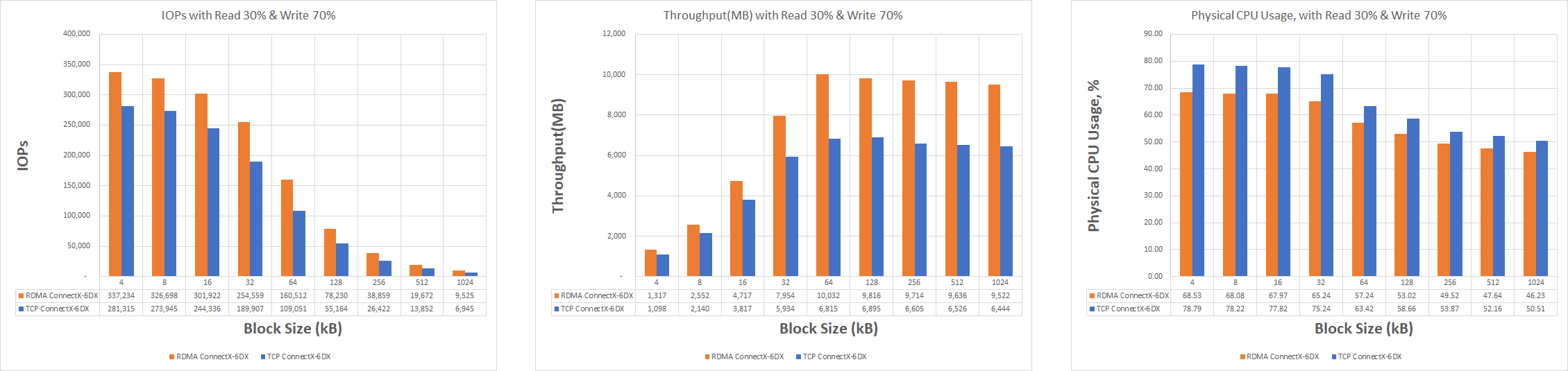
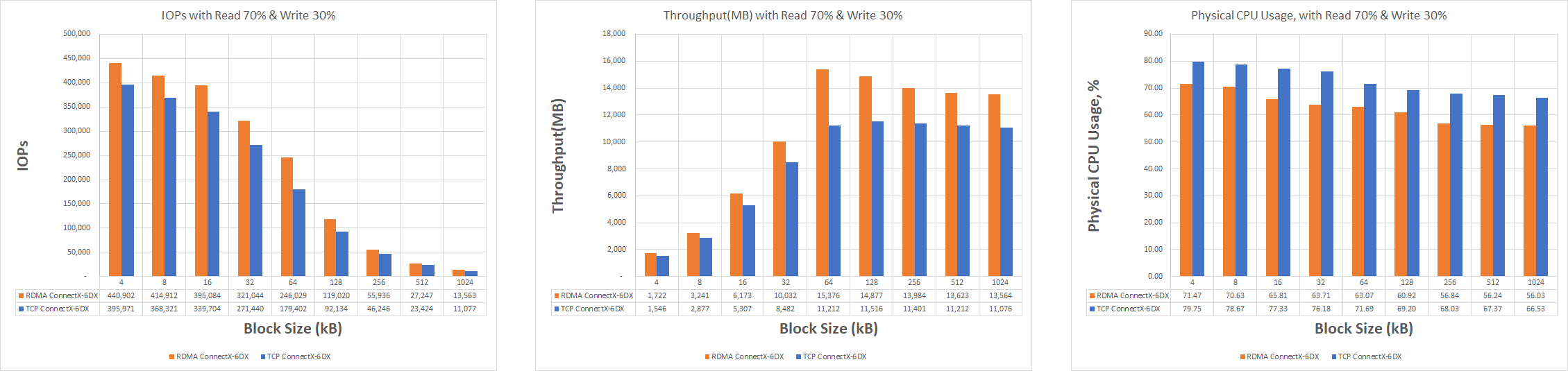
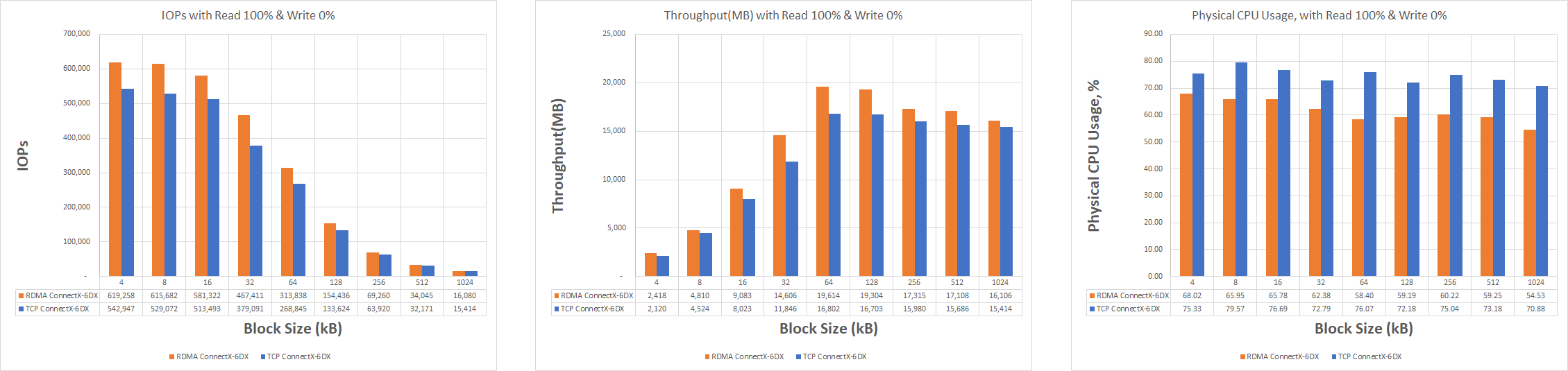
The HCI Bench used Random Read and Random Write IO patterns with various IO sizes from 4 KB to 1024 KB.
We compare the IOPS, Throughput and CPU usage between vSAN over RDMA and TCP on the cluster.
The benchmark runs had the virtual disks placed on:
Disk Group 1:
-
vSAN cache: SAMSUNG MZWLJ3T8HBLS-00007 NVMe, 2.5inch form factors, 3.84TB
-
vSAN data: 3xINTEL SSDPE2ME012T4 SSD, 2.5inch form factors, 1.2TB
Disk Group 2:
-
vSAN cache: SAMSUNG MZWLJ3T8HBLS-00007 NVMe, 2.5inch form factors, 3.84TB
-
vSAN data: 3xINTEL SSDPE2ME012T4 SSD, 2.5inch form factors, 1.2TB
Please note that these results were obtained using a FIO benchmark and with our lab configurations.
Performance with other configurations, number of ESXi servers may vary.
Conclusion
The benchmark results in this performance study show consistent supremacy of vSAN over RDMA protocol for all block sizes tested and shows that compared to vSAN over TCP.
vSAN over RDMA was able to deliver compared to vSAN over TCP for every IO size tested over NVIDIA® ConnectX®-6DX:
-
Up to 48% more IOPs.
-
Up to 48% higher throughput .
-
Up to 77% Read and up to 76% Write lower latency.
-
Up to 17.6% lower physical CPU consumption.
As result, vSAN over RDMA allows to run more VMs on the same hardware with more performance and lower latency.
Running vSAN over RoCE, which offloads the CPU from performing the data communication tasks, generates a significant performance boost that is critical in the new era of accelerated computing associated with a massive amount of data transfers.
It is expected that vSAN over RoCE will eventually replace vSAN over TCP and become the leading transport technology in vSphere-enabled data centers.
Authors
|
|
Boris Kovalev
Boris Kovalev has worked for the past several years as a Solutions Architect, focusing on NVIDIA Networking/Mellanox technology, and is responsible for complex machine learning, Big Data and advanced VMware-based cloud research and design. Boris previously spent more than 20 years as a senior consultant and solutions architect at multiple companies, most recently at VMware. He has written multiple reference designs covering VMware, machine learning, Kubernetes, and container solutions which are available at the NVIDIA Documents website. |

Last updated: