Created on Aug 14, 2022
Scope
This document provides background and guidelines on how to evaluate Nvidia Accelerated Network Computing technology through a NAT and Routing network application acceleration in K8s cluster environment.
Abbreviations and Acronyms
|
Term |
Definition |
Term |
Definition |
|---|---|---|---|
|
PF |
Physical Function |
DPDK |
Data Plane Development Kit |
|
VF |
Virtual Function |
CNI |
Container Network Interface |
|
SRIOV |
Single Root Input Output Virtualization |
RDMA |
Remote Direct Memory Access |
|
VPP |
Vector Packet Processing |
NIC |
Network Interface |
|
PMD |
Poll Mode Driver |
DAC |
Direct Attach Copper |
|
DUT |
Device Under Test |
TG |
Traffic generator |
|
MPPS |
Millions packets per second |
CNF |
Cloud native Network Function |
|
CRD |
Custom Resources Definition |
SDK |
Software Development Kit |
|
K8s |
Kubernetes |
NAT |
Network address translation |
|
TP |
Technology Preview |
SW |
Software |
|
VNF |
Virtual Network Function |
NF |
Network Function |
References
kubernetes
kubespray
Nvidia Network ConnectX-6 DX
Nvidia Network DPDK PMD
Cisco Trex - traffic generator
TRex in a few steps using Nvidia ConnectX adapters
DPDK RTE_FLOW
FD.io VPP processing platform
Introduction
Cloud computing is the preferred architecture for modern data centers, including Telecom data centers. Under this architecture, Network Functions (NF) run as a Virtualized or Containerized Network Functions (CNFs or VNFs respectively).
NFs must keep up with the growing demand for throughput, message rate and low and predictable latency coming from technologies such as 5G and AI. As cloud applications, NF greatly depends on the server’s CPUs which are general purpose and not optimized for network application. As a result, a NF may demand many CPU cores to meet the expected performance, leading to a very inefficient implementation or potentially not be able to meet the expected performance at all.
Accelerated Network Computing is an NVIDIA technology allowing to accelerate NFs using dedicate application accelerators located on a Data Processing Unit (DPU) or a SmartNIC. The NF’s application logic (or control plane) continues to run on the host’s CPU while the NF’s data plane is accelerated, through a set of well define APIs, resulting in unprecedented efficiency and performance. Accelerated Network Computing supports cloud and cloud native environments and can be used with modern orchestration frameworks such as K8s, in a multi-tenant environment.
This document demonstrates the use of Accelerated Network Computing to accelerate a sample CNF. This sample CNF implements router application which is accelerated by a ConnectX-6 Dx SmartNIC in k8s cloud environment, using generic standard DPDK APIs.
We will compare the performance and efficiency of the accelerated CNF to a SW implementation of the same CNF based on the popular Vector Packet Processing (VPP) framework.
Accelerating CNF
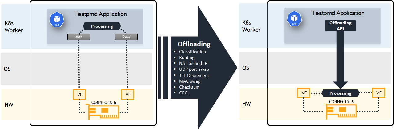
Accelerated Network Computing is the use of a physical network accelerator such as the Nvidia SmartNIC to perform NF data-plane functionalities, originally performed by the x86 CPU. Such data-plane functionalities include packets classification, packet steering, QoS, NAT, etc.
Accelerating CNF functionalities to the NIC dismisses the CNF from handling the data-plane and by that reduces CPU resources needs and makes room for the CNF to handle additional use cases. The accelerated functions are executed more efficiently on the SmartNIC accelerator than on the x86 CPU. As a result, operations can be executed in higher throughputs, lower latencies and a reduced number of CPU cores, allowing operators to load additional CNF applications on the same servers, or alternatively, use less/cheaper servers.
Beneath figure compares the two approaches. The left system runs the application on the host CPU (SW only) while on the right the application accelerates the data-plane by programing ConnectX-6 Dx application accelerator.
Solution Architecture
Key Components and Technologies
-
NVIDIA ConnectX SmartNICs
10/25/40/50/100/200 and 400G Ethernet Network Adapters
The industry-leading NVIDIA® ConnectX® family of smart network interface cards (SmartNICs) offer advanced hardware offloads and accelerations.
NVIDIA Ethernet adapters enable the highest ROI and lowest Total Cost of Ownership for hyperscale, public and private clouds, storage, machine learning, AI, big data, and telco platforms.
-
NVIDIA LinkX Cables
The NVIDIA® LinkX® product family of cables and transceivers provides the industry’s most complete line of 10, 25, 40, 50, 100, 200, and 400GbE in Ethernet and 100, 200 and 400Gb/s InfiniBand products for Cloud, HPC, hyperscale, Enterprise, telco, storage and artificial intelligence, data center applications.
-
NVIDIA Spectrum Ethernet Switches
Flexible form-factors with 16 to 128 physical ports, supporting 1GbE through 400GbE speeds.
Based on a ground-breaking silicon technology optimized for performance and scalability, NVIDIA Spectrum switches are ideal for building high-performance, cost-effective, and efficient Cloud Data Center Networks, Ethernet Storage Fabric, and Deep Learning Interconnects.
NVIDIA combines the benefits of NVIDIA Spectrum™ switches, based on an industry-leading application-specific integrated circuit (ASIC) technology, with a wide variety of modern network operating system choices, including NVIDIA Cumulus® Linux, SONiC and NVIDIA Onyx®.
-
Kubernetes
Kubernetes is an open-source container orchestration platform for deployment automation, scaling, and management of containerized applications.
-
Kubespray
Kubespray is a composition ofAnsible
playbooks, inventory, provisioning tools, and domain knowledge for generic OS/Kubernetes clusters configuration management tasks and provides:
-
A highly available cluster
-
Composable attributes
-
Support for most popular Linux distributions
-
-
NVIDIA Network Operator
The NVIDIA Network Operator simplifies the provisioning and management of NVIDIA networking resources in a Kubernetes cluster. The operator automatically installs the required host networking software - bringing together all the needed components to provide high-speed network connectivity. These components include the NVIDIA networking driver, Kubernetes device plugin, CNI plugins, IP address management (IPAM) plugin and others. The NVIDIA Network Operator works in conjunction with the NVIDIA GPU Operator to deliver high-throughput, low-latency networking for scale-out, GPU computing clusters.
-
NVIDIA PMD
Poll Mode Driver (PMD) is an open-source upstream driver, embedded within dpdk.org releases, designed for fast packet processing and low latency by providing kernel bypass for receive and send, and by avoiding the interrupt processing performance overhead.
-
TRex - Realistic Traffic Generator
TRex is an open-source, low-cost, stateful, and stateless traffic generator fueled by DPDK. It generates L4-7 traffic based on pre-processing and smart replay of L7 traffic templates. TRex amplifies both client and server side traffic and can scale up to 200Gb/sec with one UCS.
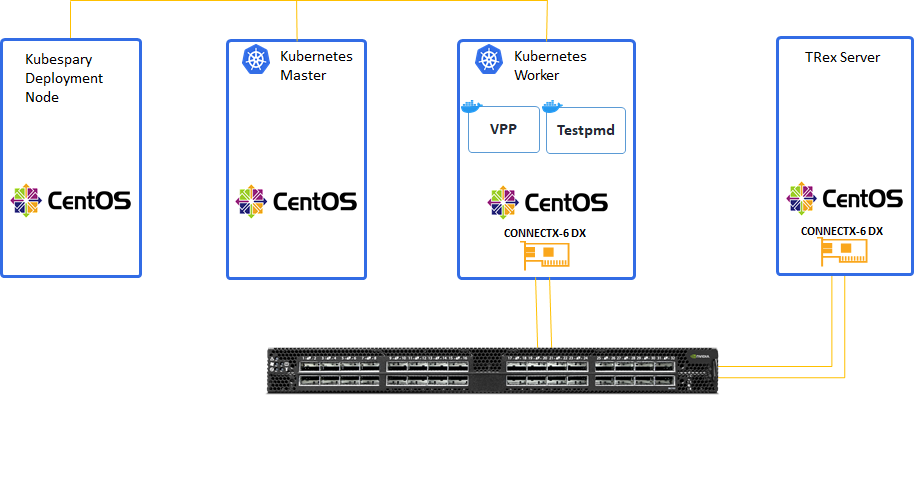
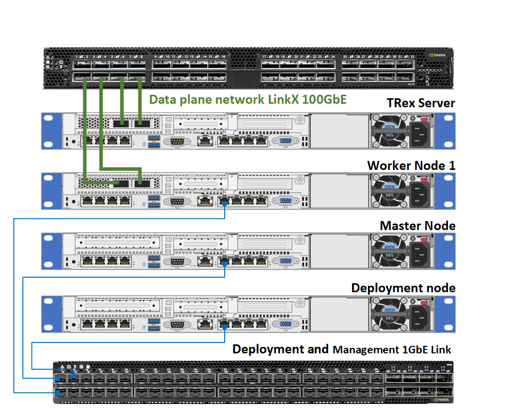
Servers Role Scheme
Server role and networking description:
-
One compute layer:
-
Deployment node
-
K8s Master node
-
K8s Worker nodes installed with Nvidia ConnectX-6 DX adapter hosting Testpmd/VPP PODs
-
TRex server node installed with Nvidia ConnectX-6 DX adapter.
-
-
Two separate networking layers:
-
Management K8s primary network of 1Gb link speed
-
High-speed 100Gb Ethernet Nvidia switch for DPDK K8s secondary network
-
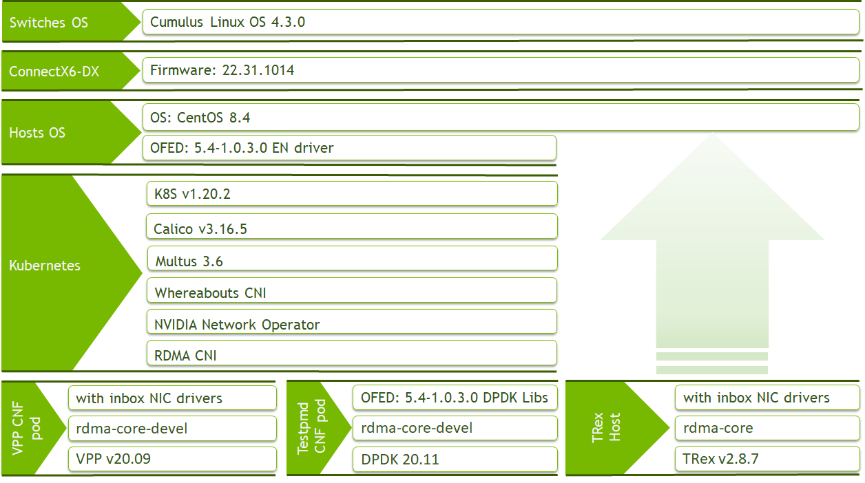
Software Stack Components
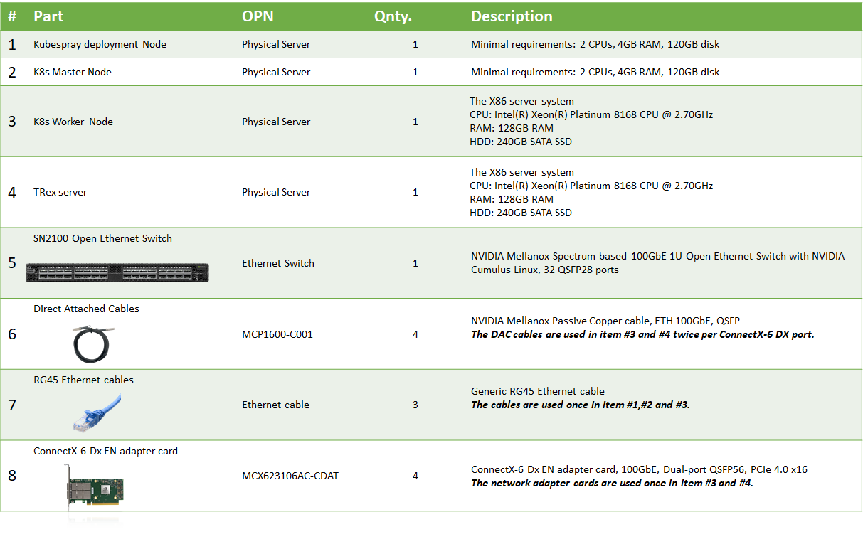
Bill of Materials
Deployment and Configuration
Wiring
Trex and worker nodes are connected to a 100GE data plane K8s secondary network.
In addition, the Worker, Master and Deployment nodes are connected to a 1GE management K8s primary network.
Host prerequisites
-
Install CentOS 8.4 for k8s master, worker and deployment nodes.
-
Install OFED >= 5.4 on worker node.
Download latest Nvidia OFED/EN. Download from Nvidia network OFED/EN official download website.
Install the required libraries and kernel modules by:Worker node console
./mlnxofedinstall --dpdk -
K8s worker node BIOS settings:
- Set electricity power saving to performance mode
- Set VT-D flag - on
- Set Turbo-boost - on
- SRIOV - enabled -
Find which NUMA node is used for NVIDIA NIC (In our example NIC name is ens2f0):
Worker node console
cat /sys/class/net/ens2f0/device/numa_nodeExtract list of cores from the same NUMA node used by NVIDIA NIC:
Worker node console
lscpu | grep NUMA -
Edit worker node grub file for optimal DPDK performance tuning and hugepages:
core-list include list of cores dedicated only for pods usage. Our example will use cores 4-23. Remaining cores not in the list can be reserved cores for K8sc system.
Using isolcpus kernel boot command-line isolates the CPUs from the kernel scheduler. This will ensure that a user-space process will not be scheduled by the kernel.intel_iommu=on iommu=pt default_hugepagesz=1G hugepagesz=1G hugepages=32 isolcpus=<core-list>
RDMA subsystem configuration
RDMA subsystem configuration is required on each Worker Node.
-
Set PF interfaces to link "UP" on boot (In our example NICs ens2f0, ens2f1):
Worker node console
sed -i 's/\(ONBOOT=\)no/\1yes/g' /etc/sysconfig/network-scripts/ifcfg-ens2f0 sed -i 's/\(ONBOOT=\)no/\1yes/g' /etc/sysconfig/network-scripts/ifcfg-ens2f1 -
Set RDMA subsystem network namespace mode to exclusive mode
RDMA subsystem network namespace mode (netns parameter in ib_core module) in exclusive mode allows network namespace isolation for RDMA workloads on the Worker Node servers. Please create /etc/modprobe.d/ib_core.conf configuration file to change ib_core module parameters:Worker node console
echo "options ib_core netns_mode=0" > /etc/modprobe.d/ib_core.conf
dracut -f
Reboot worker server:
Worker node console
rebootAfter the server comes back, check netnsmode:
Worker node console
rdma systemOutput should be: "netns exclusive"
Installing Kubespray on deployment server
Deployment node console
yum install python3-pip jq git -y
git clone https://github.com/kubernetes-sigs/kubespray.git
cd kubespray
pip3 install -r requirements.txt
Deploy K8s cluster with Kubespray
-
Set local IPs for master and worker nodes and generate configuration file per each:
Deployment node console
cp -rfp inventory/sample inventory/mycluster
declare -a IPS=(192.168.200.3 192.168.200.2)
CONFIG_FILE=inventory/mycluster/hosts.yaml python3 contrib/inventory_builder/inventory.py ${IPS[@]}
Validate cluster information in file inventory/mycluster/hosts.yaml and edit in case needed.
In this example node1 is master node and node2 is worker node. See file example for this deployment:all: hosts: node1: ansible_host: 192.168.200.3 ip: 192.168.200.3 access_ip: 192.168.200.3 node2: ansible_host: 192.168.200.2 ip: 192.168.200.2 access_ip: 192.168.200.2 children: kube-master: hosts: node1: kube-node: hosts: node2: etcd: hosts: node1: k8s-cluster: children: kube-master: kube-node: calico-rr: hosts: {} -
Change deployment parameters in file inventory/mycluster/group_vars/k8s-cluster/k8s-cluster.yml
Set k8s version to :kube_version: v1.21.5 -
Set RSA key for passwordless ssh authentication for Kubespary server
Generate RSA key ~/.ssh/id_rsa :Deployment node console
ssh-keygenCopy RSA key to master and worker nodes:
Deployment node console
ssh-copy-id root@<Node-IP> -
Install K8s cluster:
Deployment node console
ansible-playbook -i inventory/mycluster/hosts.yaml -e 'ansible_python_interpreter=/usr/bin/python3' --become --become-user=root cluster.ymlHere is an example output of successful installation:
PLAY RECAP ************************************************************************************************************************************************************************************************* localhost : ok=1 changed=0 unreachable=0 failed=0 skipped=0 rescued=0 ignored=0 node1 : ok=551 changed=24 unreachable=0 failed=0 skipped=1142 rescued=0 ignored=0 node2 : ok=350 changed=11 unreachable=0 failed=0 skipped=587 rescued=0 ignored=0 Tuesday 24 November 2020 09:31:22 +0200 (0:00:00.029) 0:04:50.249 ****** =============================================================================== kubernetes-apps/ansible : Kubernetes Apps | Lay Down CoreDNS Template ------------------------------------------------------------------------------------------------------------------------------ 14.73s container-engine/docker : ensure docker packages are installed ------------------------------------------------------------------------------------------------------------------------------------- 10.24s kubernetes/master : Master | wait for kube-scheduler ------------------------------------------------------------------------------------------------------------------------------------------------ 8.52s kubernetes-apps/network_plugin/multus : Multus | Start resources ------------------------------------------------------------------------------------------------------------------------------------ 7.91s kubernetes-apps/ansible : Kubernetes Apps | Start Resources ----------------------------------------------------------------------------------------------------------------------------------------- 7.76s network_plugin/multus : Multus | Copy manifest files ------------------------------------------------------------------------------------------------------------------------------------------------ 4.43s network_plugin/calico : Calico | Create calico manifests -------------------------------------------------------------------------------------------------------------------------------------------- 4.37s Gather necessary facts ------------------------------------------------------------------------------------------------------------------------------------------------------------------------------ 4.34s kubernetes/preinstall : Get current version of calico cluster version ------------------------------------------------------------------------------------------------------------------------------- 4.17s download : check_pull_required | Generate a list of information about the images on a node --------------------------------------------------------------------------------------------------------- 4.11s network_plugin/calico : Get current version of calico cluster version ------------------------------------------------------------------------------------------------------------------------------- 3.88s kubernetes/master : kubeadm | Check if apiserver.crt contains all needed SANs ----------------------------------------------------------------------------------------------------------------------- 3.52s kubernetes/master : slurp kubeadm certs ------------------------------------------------------------------------------------------------------------------------------------------------------------- 3.27s policy_controller/calico : Create calico-kube-controllers manifests --------------------------------------------------------------------------------------------------------------------------------- 2.98s network_plugin/cni : CNI | Copy cni plugins --------------------------------------------------------------------------------------------------------------------------------------------------------- 2.92s network_plugin/calico : Start Calico resources ------------------------------------------------------------------------------------------------------------------------------------------------------ 2.82s kubernetes/master : Backup old certs and keys ------------------------------------------------------------------------------------------------------------------------------------------------------- 2.75s kubernetes-apps/cluster_roles : PriorityClass | Create k8s-cluster-critical ------------------------------------------------------------------------------------------------------------------------- 2.60s network_plugin/calico : Calico | wait for etcd ------------------------------------------------------------------------------------------------------------------------------------------------------ 2.44s policy_controller/calico : Start of Calico kube controllers ----------------------------------------------------------------------------------------------------------------------------------------- 2.23s -
Set "worker" label for node2:
Master node console
kubectl label nodes node2 node-role.kubernetes.io/worker=
NVIDIA Network Operator Installation for K8S Cluster
Nvidia Network Operator leverages Kubernetes CRDs and Operator SDK to manage Networking related Components in order to enable Fast networking and RDMA for workloads in K8s cluster. The Fast Network is a secondary network of the K8s cluster for application that require high bandwidth or low latency.
To make it work, you need to provision and configure several components. All Operator configuration and installation steps should be performed from the K8S Master Node with the root user account.
Perpetrations
-
Install Helm on master node server following Helm install documentation.
-
Install additional RDMA CNI plugin
RDMA CNI plugin allows network namespace isolation for RDMA workloads in a containerized environment.
Deploy CNI's using the following YAML files:Master node console
kubectl apply -f https://raw.githubusercontent.com/Mellanox/rdma-cni/master/deployment/rdma-cni-daemonset.yaml -
To ensure the plugin is installed correctly, run the following command:
Master node console
kubectl -n kube-system get pods -o wide | egrep  "rdma"
kube-rdma-cni-ds-c9cml                        1/1     Running   0          22s     1.1.1.2        node1   <none>           <none>
kube-rdma-cni-ds-cw22n                        1/1     Running   0          22s     1.1.1.3        node2   <none>           <none>
kube-rdma-cni-ds-dh28z                        1/1     Running   0          22s     1.1.1.4        node3   <none>           <none>
Deployment
-
Add the NVIDIA Network Operator Helm repository:
Master node console
helm repo add mellanox https://mellanox.github.io/network-operator helm repo update -
Create values.yaml file (example):
nfd: enabled: true sriovNetworkOperator: enabled: true # NicClusterPolicy CR values: deployCR: true ofedDriver: deploy: false nvPeerDriver: deploy: false rdmaSharedDevicePlugin: deploy: false sriovDevicePlugin: deploy: false secondaryNetwork: deploy: true cniPlugins: deploy: true image: containernetworking-plugins repository: mellanox version: v0.8.7 imagePullSecrets: [] multus: deploy: true image: multus repository: nfvpe version: v3.6 imagePullSecrets: [] config: '' ipamPlugin: deploy: true image: whereabouts repository: mellanox version: v0.3 imagePullSecrets: [] -
Deploy the operator:
Master node console
helm install -f values.yaml -n network-operator --create-namespace --wait mellanox/network-operator --generate-name

NAME: network-operator
LAST DEPLOYED: Sun Jul 11 23:06:54 2021
NAMESPACE: network-operator
STATUS: deployed
REVISION: 1
TEST SUITE: None
NOTES:
Get Network Operator deployed resources by running the following commands:

$ kubectl -n network-operator get pods
$ kubectl -n mlnx-network-operator-resources get pods
To ensure that the Operator is deployed correctly, run the following commands:
Master node console
kubectl -n network-operator get pods -o wide
NAME                                                              READY   STATUS    RESTARTS   AGE   IP             NODE    NOMINATED NODE   READINESS GATES
network-operator-1635068237-57c94ff559-fm7kb                      1/1     Running   0          22s   10.233.90.10   node1   <none>           <none>
network-operator-1635068237-node-feature-discovery-master-ms57h   1/1     Running   0          22s   10.233.90.9    node1   <none>           <none>
network-operator-1635068237-node-feature-discovery-worker-fqw9g   1/1     Running   0          22s   10.233.96.3    node2   <none>           <none>
network-operator-1635068237-node-feature-discovery-worker-kh29n   1/1     Running   0          22s   10.233.90.8    node1   <none>           <none>
network-operator-1635068237-sriov-network-operator-5c9486726pj9   1/1     Running   0          22s   10.233.90.7    node1   <none>           <none>
sriov-network-config-daemon-gj7zp                                 1/1     Running   0          16s   10.7.215.90    node2   <none>           <none>
High-speed network configuration
-
After installing the operator, please check the SriovNetworkNodeState CRs to see all SRIOV-enabled devices in worker node.
In our deployment chosen network interfaces are with name ens2f0,ens2f1. To review the interface status please use following command:Master node console
kubectl -n network-operator get sriovnetworknodestates.sriovnetwork.openshift.io node2 -o yaml ... - deviceID: 101d driver: mlx5_core linkSpeed: 100000 Mb/s linkType: ETH mac: 1c:34:da:54:cd:34 mtu: 1500 name: ens2f0 pciAddress: 0000:61:00.0 totalvfs: 2 vendor: 15b3 - deviceID: 101d driver: mlx5_core linkSpeed: 100000 Mb/s linkType: ETH mac: 1c:34:da:54:cd:35 mtu: 1500 name: ens2f1 pciAddress: 0000:61:00.1 totalvfs: 2 vendor: 15b3 ... -
Create SriovNetworkNodePolicy CR - policy-1.yaml file for first PF interface and policy-2.yaml file for second PF interface, by specifying interfaces name and vendor in the 'nicSelector' (this example include ens2f0 and ensf1 interfaces):
apiVersion: sriovnetwork.openshift.io/v1
kind: SriovNetworkNodePolicy
metadata:
  name: mlnxnics-1
  namespace: network-operator
spec:
  nodeSelector:
    feature.node.kubernetes.io/network-sriov.capable: "true"
  resourceName: mlnx2f0
  mtu: 1500
  numVfs: 2
  nicSelector:
    vendor: "15b3"
    pfNames: [ "ens2f0" ]
  deviceType: netdevice
  isRdma: true
apiVersion: sriovnetwork.openshift.io/v1 kind: SriovNetworkNodePolicy metadata: name: mlnxnics-2 namespace: network-operator spec: nodeSelector: feature.node.kubernetes.io/network-sriov.capable: "true" resourceName: mlnx2f1 mtu: 1500 numVfs: 2 nicSelector: vendor: "15b3" pfNames: [ "ens2f1" ] deviceType: netdevice isRdma: true -
Deploy policy-1.yaml and policy-2.yaml:
Master node console
kubectl apply -f policy-1.yaml kubectl apply -f policy-2.yaml -
Create a SriovNetwork CRs - network-1.yaml and network-2.yaml files, which refer to the 'resourceName' as defined in SriovNetworkNodePolicy per each PF interface (in this example, 1.1.1.0/24 and 2.2.2.0/24 defined as CIDR range for high-speed network):
apiVersion: sriovnetwork.openshift.io/v1
kind: SriovNetwork
metadata:
  name: "netmlnx2f0"
  namespace: network-operator
spec:
  ipam: |
    {
      "datastore": "kubernetes",
      "kubernetes": {
         "kubeconfig": "/etc/cni/net.d/whereabouts.d/whereabouts.kubeconfig"
      },
      "log_file": "/tmp/whereabouts.log",
      "log_level": "debug",
      "type": "whereabouts",
      "range": "1.1.1.0/24"
    }
  vlan: 0
  networkNamespace: "default"
  spoofChk: "off"
  resourceName: "mlnx2f0"
  linkState: "enable"
  metaPlugins: |
    {
      "type": "rdma"
    }
apiVersion: sriovnetwork.openshift.io/v1 kind: SriovNetwork metadata: name: "netmlnx2f1" namespace: network-operator spec: ipam: | { "datastore": "kubernetes", "kubernetes": { "kubeconfig": "/etc/cni/net.d/whereabouts.d/whereabouts.kubeconfig" }, "log_file": "/tmp/whereabouts.log", "log_level": "debug", "type": "whereabouts", "range": "2.2.2.0/24" } vlan: 0 networkNamespace: "default" spoofChk: "off" resourceName: "mlnx2f1" linkState: "enable" metaPlugins: | { "type": "rdma" } -
Deploy network-1.yaml and network-2.yaml:
Master node console
kubectl apply -f network-1.yaml kubectl apply -f network-2.yaml -
Validating the deployment
Check deployed network:Master node console
kubectl get network-attachment-definitions.k8s.cni.cncf.io
NAME         AGE
netmlnx2f0   3m
netmlnx2f1   3m
Check Worker Node resources:
kubectl describe nodes node2
...
Addresses:
  InternalIP:  192.168.200.2
  Hostname:    node2
Capacity:
  cpu:                 24
  ephemeral-storage:   45093936Ki
  hugepages-1Gi:       32Gi
  hugepages-2Mi:       0
  memory:              96076Mi
  nvidia.com/mlnx2f0:  2
  nvidia.com/mlnx2f1:  2
  pods:                110
Allocatable:
  cpu:                 23900m
  ephemeral-storage:   41558571349
  hugepages-1Gi:       32Gi
  hugepages-2Mi:       0
  memory:              62952Mi
  nvidia.com/mlnx2f0:  2
  nvidia.com/mlnx2f1:  2
  pods:                110
...
Topology manager settings
Performance sensitive applications requires topology aligned resource allocation avoiding incurring of additional latency.
Topology manager ensure devices being allocated from Uniform Memory Access (NUMA) Nodes.
For additional information please refer to Control Topology Management Policies on a node and Control Topology Management Policies on a node.
-
Define the cores reserved for K8s operational system services:
Worker node console
numactl --hardware
available: 1 nodes (0)
node 0 cpus: 0 1 2 3 4 5 6 7 8 9 10 11 12 13 14 15 16 17 18 19 20 21 22 23
node 0 size: 92611 MB
node 0 free: 53873 MB
node distances:
node   0
  0:  10
In our example Numa node 0 includes cores 0-23.
To reserve cores 0-3 for K8s add this line to kubelet-config.yaml file:/etc/kubernetes/kubelet-config.yaml
reservedSystemCPUs:0-3Now cores 4-23 are free for pods usage. Make sure grub file is set with same core-list for isolated cores (isolcpus=4-23) as specified in hot prerequisites section.
-
Enable topology manger by adding the following lines to kubelet configuration file - /etc/kubernetes/kubelet-config.yaml in worke node:
/etc/kubernetes/kubelet-config.yaml
cpuManagerPolicy: static reservedSystemCPUs: 0-3 topologyManagerPolicy: single-numa-node -
Due to changes in cpuManagerPolicy, you should remove /var/lib/kubelet/cpu_manager_state and restart kubelet service on Worker Node as follow:
rm -f /var/lib/kubelet/cpu_manager_state
systemctl daemon-reload && systemctl restart kubelet
Configuring VFs to be trusted
-
Extract PF network interface PCI slot number using this command (In our example PCI slot number is 61:00.0):
Worker node console
lspci | grep "Mellanox" | grep -v "Virtual" | cut -d " " -f 1 -
Using mlxreg to configure ALL VF's to be trusted by firmware:
Worker node console
mlxreg -d 61:00.0 --reg_id 0xc007 --reg_len 0x40 --indexes "0x0.0:32=0x80000000" --yes --set "0x4.0:32=0x1" mlxreg -d 61:00.1 --reg_id 0xc007 --reg_len 0x40 --indexes "0x0.0:32=0x80000000" --yes --set "0x4.0:32=0x1" -
Set VF's to be trusted from driver side (In our example VFs are part of interface ens2f0,ensf1):
Worker node console
PF=($(ibdev2netdev | grep mlx5_ | awk '{print $5}')); for i in ${PF[@]}; do cat /sys/class/net/${i}/settings/vf_roce &> /dev/null; RESULT=$?; if [ $RESULT -eq 0 ]; then VFS=($(cat /sys/class/net/${i}/settings/vf_roce | awk '{print $2}' | tr -d :)); for j in ${VFS[@]}; do ip link set $i vf $j trust on; echo "Set inteface $i VF $j to trusted"; done fi; done -
Bind and unbind VFs ethernet driver:
Worker node console
VFS_PCI=($(lspci | grep "Mellanox" | grep "Virtual" | cut -d " " -f 1));
     for i in ${VFS_PCI[@]};
     do
         echo "unbinding VF $i";
         echo "0000:${i}" >> /sys/bus/pci/drivers/mlx5_core/unbind;
		 echo "binding VF $i";
         echo "0000:${i}" >> /sys/bus/pci/drivers/mlx5_core/bind;
     done
TRex server installation with L2 interfaces
For building Trex server please follow the steps in this guide: Installing TRex in a few steps using Nvidia ConnectX adapters.
-
Make sure to configure MAC based config.
-
Set destination MAC address for first TRex port of testpmd or VPP port 0 MAC address.
-
Set destination MAC address for second TRex port of testpmd or VPP port 1 MAC address.
See install process example here:
Performance Evaluation
In this section will evaluate the performance of a CNF doing NAT and IPv4 Routing. The SW implementation will be based on VPP while the accelerated use case will use Testpmd to program the SmartNIC accelerator with the same data-plane as the VPP application.
Testing bidirectional IPv4 Routing and NAT Scheme
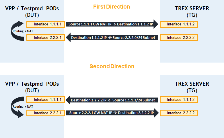
-
VPP/Testpmd pods are set with two interfaces 1.1.1.1/24 and 2.2.2.1/24
-
TRex server is set with the two interfaces 1.1.1.2/24 and 2.2.2.2/2
-
Source subnet 2.2.2.0/24 is hided behind gateway IP of 1.1.1.1 when packet destination is Trex IP 1.1.1.2
-
Source subnet 1.1.1.0/24 is hided behind gateway IP of 2.2.2.1 when packet destination is Trex IP 2.2.2.2
-
Packets from Trex subnet 2.2.2.0/24 destined to Trex IP 1.1.1.2 are routed and nated back to Trex by Testpmd/VPP pods.
-
Packets from Trex subnet 1.1.1.0/24 destined to Trex IP 2.2.2.2 are routed and nated back to Trex by Testpmd/VPP pods.
VPP bring up
Launch CNF with CentOS
In this Pod CR example:
-
network-1 and network-2 attached
-
8Gb hugepages mounted
-
2 SRIOV interfaces attached from nvidia.com/mlnx2f0, nvidia.com/mlnx2f1 resources.
-
8 Cores allocated
Launch POD:
Master node console
kubectl create -f VPP_PodCR.yaml
Install VPP application
This guide assume no pre built container image is available for download.
In order to install VPP login into container bash shell:
Master node console
kubectl exec --stdin --tty vpp -- /bin/bash
Continue with VPP installation following this guide: Build and Run Vector Packet Processing (VPP) Applications Over NVIDIA SmartNICs.
Performance evaluation for VPP
Configure VPP to perform NAT
-
Configure VPP with L3 interfaces - make sure to configure L3 IPv4 interfaces with the correct IPs.
In our example first interface is set to 1.1.1.1/24 and second interface is set to 2.2.2.1/24.VPP container console
## Start VPP CLI ## $HOME-PATH/vpp/build-root/build-vpp-native/vpp/bin/./vppctl ## Set 2 L3 interfaces with IP and subnet ## set int ip address HundredGigabitEthernet61/0/2 1.1.1.1/24 set interface state HundredGigabitEthernet61/0/2 up set int ip address HundredGigabitEthernet61/0/3 2.2.2.1/24 set interface state HundredGigabitEthernet61/0/3 up -
Set static ARP entries pointing Trex server interfaces
VPP container console
set ip neighbor HundredGigabitEthernet61/0/2 1.1.1.2 <Trex_first_port_MAC_Adress> static set ip neighbor HundredGigabitEthernet61/0/3 2.2.2.2 <Trex_second_port_MAC_Adress> static -
Set NAT for 2 interfaces
NAT behind port HundredGigabitEthernet61/0/2 GW IP 1.1.1.1 of traffic coming from port HundredGigabitEthernet61/0/3
NAT behind port HundredGigabitEthernet61/0/3 GW IP 2.2.2.1 of traffic coming from port HundredGigabitEthernet61/0/2VPP container console
nat44 add interface address HundredGigabitEthernet61/0/2
nat44 add interface address  HundredGigabitEthernet61/0/3
set interface nat44 out  HundredGigabitEthernet61/0/2 output-feature
set interface nat44 out  HundredGigabitEthernet61/0/3 output-feature
nat44 forwarding enable
nat addr-port-assignment-alg default
Testpmd SmartNIC accelerating bring up
Create container image for Testpmd application
-
Clone Dockerfile image builder:
git clone https://github.com/Mellanox/mlnx_docker_dpdk cd mlnx_docker_dpdk/ git checkout origin/ninja-build -
Create image in local Docker server:
OS version - CentOS 8.4.2105
DPDK version - 20.11
Nvidia OFED - 5.4-1.0.3.0docker build --build-arg OS_VER=8.4.2105 --build-arg DPDK_VER=20.11 --build-arg OFED_VER=5.4-1.0.3.0 -t centos8.4/dpdk20.11:ofed5.4 . -
Once image created it is recommended to push it to docker hub account repository.
For instructions visit this link: Pushing docker image to Docker hub
The repository in Docker hub will contain the desired image which can be specified in POD definition yaml file (In our example file TestpmdPodCR.yaml).
Launch CNF with Testpmd application
In this Pod CR example:
-
network-1 and network-2 attached
-
8Gb hugepages mounted
-
2 SRIOV interfaces attached from nvidia.com/mlnx2f0, nvidia.com/mlnx2f1 resources.
-
8 Cores allocated
Launch POD:
Master node console
kubectl create -f TestpmdPodCR.yaml
Performance evaluation for Testpmd SmartNIC accelerating
Testpmd flow composition
This section explains how to run testpmd application with accelerating Routing and NAT actions by structuring flows.
Testpmd uses DPDK standard RTE_FLOW API to accelerate flows. Here is an example and description on how it is done for imitating NAT and routing:
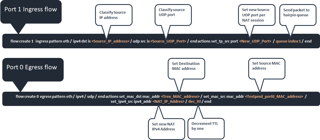
In addition IPv4 header checksum and packet CRC is done automatically by the NIC.
Single flow test
Run Testpmd application with 2 hairpin queues and single core over 2 VFs:
TestPMD POD CLI
cd /usr/src/dpdk-20.11/build/app/
./dpdk-testpmd -c 0x30 -n 4 -m 1024 -w 0000:61:00.2 -w 0000:61:00.4 -- --hairpinq=2 --hairpin-mode=0x12 --burst=64 --txd=1024 --rxd=1024 --mbcache=512 --rxq=1 --txq=1 --nb-cores=1 --flow-isolate-all -a -i
Parameters definition:
-
Number of cores mask (example for 2 cores) -c 0x3
-
Number Numa Channels -n 4
-
Hugepages amount of memory -m 1024
-
PCI slot -w <number>
-
Amount of RX/TX queues --rxq=2 --txq=2 --nb-cores=1
-
Setting 2 hairpin queus --hairpinq=2
-
Hairpin mode --hairpin-mode values: 0x10 - explicit tx rule, 0x02 - hairpin ports paired
-
--flow-isolate-all ensures all traffic is received through the configured flow rules only
-
Single packet processing PMD core --nb-cores=1
-
Setting port RX/TX descriptors size --txd=1024 --rxd=1024
From Testpmd CLI insert first direction flow for accelerating:
Testpmd CLI
testpmd> flow create 1 ingress pattern eth / ipv4 src is <Src_IP2> / udp src is <S_port> / end actions set_tp_src port <New_S_port> / queue index 1 / end
testpmd> flow create 0 egress pattern eth / ipv4 / udp / end actions set_mac_dst mac_addr <TREX_MAC0> / set_mac_src mac_addr <TESTPMD_MAC0> / set_ipv4_src ipv4_addr <NAT_IP2> / dec_ttl / end
Parameters value:
-
<Src_IP2> == 2.2.2.2
-
<S_port> == 1002
-
<New_S_port> == 1003
-
<TREX_MAC0> ← First Trex port 0 MAC address
-
<TESTPMD_MAC0> ← First testpmd port 0 MAC address
-
<NAT_IP2> == 2.2.2.1
From Testpmd CLI insert second direction flow for accelerating:
Testpmd CLI
testpmd> flow create 0 ingress pattern eth / ipv4 src is <Src_IP1> / udp src is <S_port> / end actions set_tp_src port <New_S_port> / queue index 2 / end
testpmd> flow create 1 egress pattern eth / ipv4 / udp / end actions set_mac_dst mac_addr <TREX_MAC1> / set_mac_src mac_addr <TESTPMD_MAC1> / set_ipv4_src ipv4_addr <NAT_IP1> / dec_ttl / end
Parameters value:
-
<Src_IP1> == 1.1.1.2
-
<S_port> == 1002
-
<New_S_port> == 1003
-
<TREX_MAC1> ← Second Trex port 1 MAC address
-
<TESTPMD_MAC1> ← Second testpmd port 1 MAC address
-
<NAT_IP1> == 1.1.1.1
Multiple flow test
For high volume of flows it is possible to list all desired flows in a file. Testpmd application will load all flows by reading this file.
This section explain how to create a "flow" file by writing flows into it using bash script.
Modify this script "create_flows.sh" to generate multiple NAT flow sessions iterating source UDP port per single user on each direction.
-
NAT_IP1 ← The IP of the first Testpmd port
-
NAT_IP2 ← The IP of the second Testpmd port
-
MIN_PORT ← Minimal source UDP port range
-
MAX_PORT ← Maximal source UDP port range
-
TREX_MAC0 ← First Trex port 0 MAC address
-
TREX_MAC1 ← Second Trex port 1 MAC address
-
TESTPMD_MAC0 ← First testpmd port 0 MAC address
-
TESTPMD_MAC1 ← Second testpmd port 1 MAC address
-
Src_IP1 ← IP of the first Trex port
-
Src_IP2 ← IP of the second Trex port
-
PATH ← Path for flows file directory (In our example/usr/src/dpdk-20.11/build/app/flows.txt).
Execute flow creation script in Testpmd binary directory:
TestPMD POD CLI
chmod +x create_flows.sh
./create_flows.sh
Run testpmd while loading all flows from a file:
TestPMD POD CLI
cd /usr/src/dpdk-20.11/build/app/
./dpdk-testpmd -c 0x30 -n 4 -m 1024 -w 0000:61:00.2 -w 0000:61:00.4 -- --hairpinq=2 --hairpin-mode=0x12 --burst=64 --txd=1024 --rxd=1024 --mbcache=512 --rxq=1 --txq=1 --nb-cores=1 --flow-isolate-all -a -i
Load flows from a file (This action can take a couple of minutes):
Testpmd CLI
testpmd>load flows.txt
Testing performance using Trex
Upload Trex_UDP_L3_P0.py python script to Trex root directory:
Upload Trex_UDP_L3_P1.py python script to Trex root directory:
Make sure to follow these setting for single user and 5k sessions per direction (Total 10k sessions):
-
User refer to source IPv4 address
-
Session refer to source UDP port range
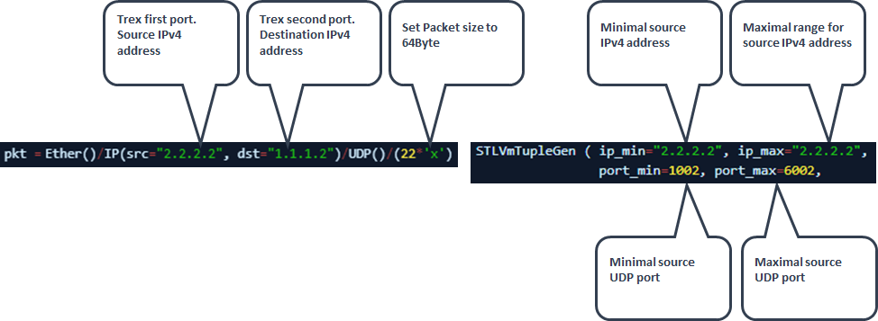
Single session test
If testing single session per single user 'port_min' should be equal to 'port_max' (In ouer example both should be equal to 1002).
Run UDP_L3_P0.py & UDP_L3_P1.py scripts to generate packet towards DUT:
Increase the amount of packet per second as long as the number of transmit packets is equal to receive.
Trex console
./trex-console
trex>start -f UDP_L3_P0.py -m 74mpps -p 0
trex>start -f UDP_L3_P1.py -m 74mpps -p 1
Parameters definition:
-
-f Points the desired Trex script
-
-m Specifies amount of packer per second
-
-p Sets the desired port
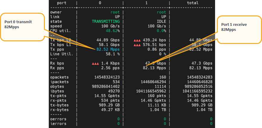
Validate number of transmitted packets from port 0 received back on port 1:
Trex console
trex>tui
Uni-directional test results example:
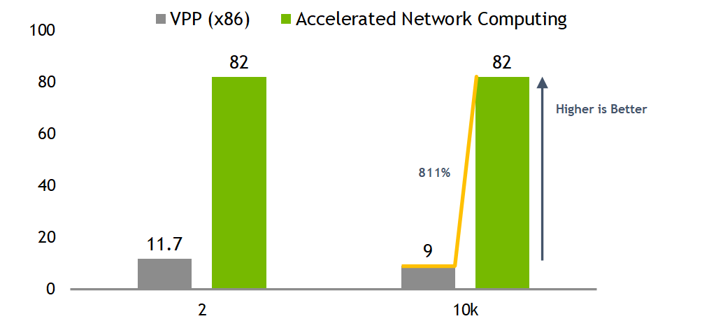
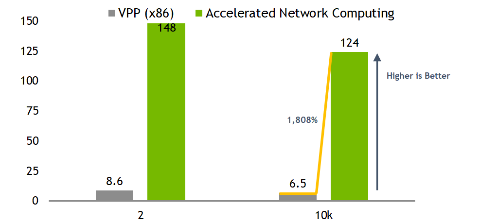
Performance summary
Bidirectional test results showing more than 12x times better performances using same x86 host resources of single core while taking advantage of SmartNIC accelerating capabilities.
It will highlight the superior value of network packet processing in SmartNIC hardware vs SW processing of x86 CPU only.
Uni-directional test results
Bi-directional test results
Authors
|
|
Amir Zeidner For several years, Amir has worked as a Solutions Architect primarily in the Telco space, leading advanced solutions to answer 5G, NFV, and SDN networking infrastructure requirements. Amir’s expertise in data plane acceleration technologies, such as Accelerated Switching and Network Processing (ASAP²) and DPDK, together with a deep knowledge of open-source cloud-based infrastructures, allows him to promote and deliver unique end-to-end NVIDIA Networking solutions throughout the Telco world. |

Last updated: