Scope
This technical preview document is intended for previewing NVIDIA Host-Based Networking (HBN) service running on BlueField DPU in a Kubernetes use case.
Abbreviations and Acronyms
|
Term |
Definition |
Term |
Definition |
|---|---|---|---|
|
BGP |
Border Gateway Protocol |
LACP |
Link Aggregation Control Protocol |
|
CNI |
Container Network Interface |
LAG |
Link Aggregation |
|
DOCA |
Datacenter-on-a-Chip Architecture |
PF |
Physical Function |
|
DPU |
Data Processing Unit |
SDN |
Software Defined Networking |
|
ECMP |
Equal-Cost Multi Pathing |
SRIOV |
Single-Root IO Virtualization |
|
EVPN |
Ethernet Virtual Private Network |
VF |
Virtual Function |
|
HBN |
Host-Based Networking |
VXLAN |
Virtual Extensible Local-Area-Network |
|
K8s |
Kubernetes |
|
|
Introduction
The BlueField®-2 data processing unit (DPU) provides innovative offload, acceleration, security, and efficiency in every host.
BlueField-2 combines the power of ConnectX®-6 with programmable Arm cores and hardware acceleration engines for software-defined storage, networking, security, and management workloads.
NVIDIA HBN is a service running on the DPU, which simplifies network provisioning by terminating the Ethernet layer 2 network in the DPU, allowing the physical network to become more of a "plug-and-play" utilizing a BGP-managed layer 3 network.
With HBN, the workload servers are connected to the physical switches over router ports, using unnumbered BGP configuration, which is automatic and does not require any IP subnet and address allocation for the underlay network, and provides a built-in active-active high-availability and load balancing based on ECMP.
The DPUs in the servers act as virtual tunnel endpoints (VTEPs) for the host network, providing a stretched layer 2 between all the nodes in the cluster over VXLAN using EVPN technology.
The configuration of HBN on the DPUs is almost identical to the configuration of physical NVIDIA switches, as it uses the same NVUE CLI commands, or NVUE programmatic API.
At the time of publishing this document, there are some throughput limitations with HBN that will be addressed in the upcoming releases. RoCE support by HBN will be added in future releases as well.
References
Solution Architecture
Logical Design
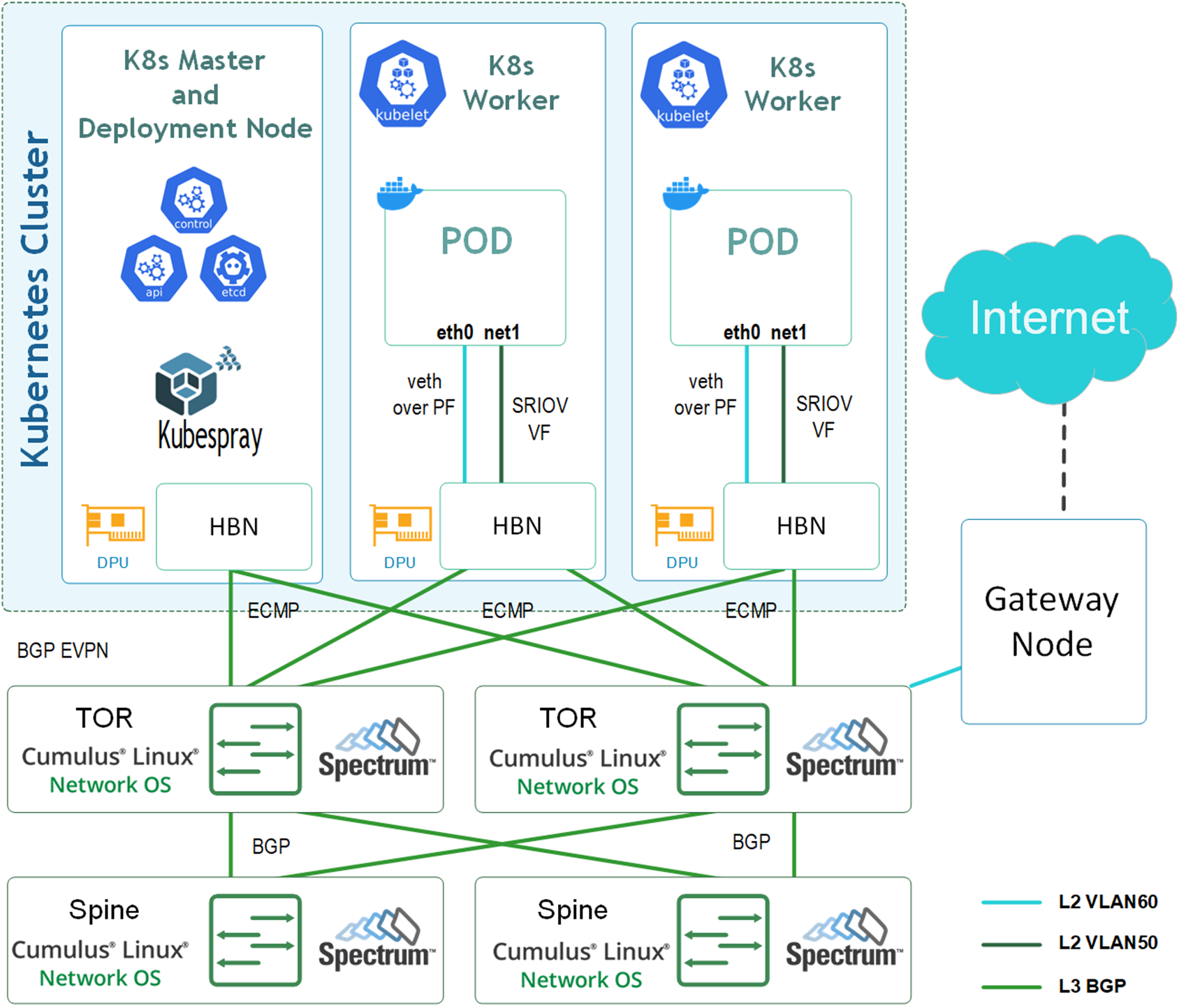
Our deployment uses HBN to create two stretched layer 2 networks: One for the primary network (Calico running in IP-in-IP configuration) using VLAN 60 and one for a secondary SR-IOV network using VLAN 50.
The primary network runs over the physical function (PF) of the DPU, using veth-based kernel interfaces (Virtual Ethernet Interfaces) for the pods named eth0, while the secondary network allocates virtual functions (VFs) for each pod, named net1, which are allocated out of a pool of up to 16 VFs supported by HBN per DPU. This network can utilize the DPU's hardware acceleration capabilities. Support for RoCE traffic will be added through it soon.
The external access for the deployment (i.e., lab network access and Internet connectivity) is achieved through a gateway node connected to a leaf and acting as the default gateway for the management network 172.60.0.0/24 on VLAN 60.
The traffic that traverses between the servers through the leaf switches (with an exception of the gateway node) solely uses layer 3 (packets routed between BGP neighbors), and utilizes ECMP for high-availability and load balancing.
The gateway node used in this setup uses a VTEP in the leaf.
Please note that the configuration and deployment of the gateway node used to provide external access in this example is not included in the scope of this document.
Please note that the gateway solution used in this example does not support a high-availability scenario. It is recommended to use a high availablity gateway deployment in a production environment (i.e., connected to more than a single leaf switch).
The presented deployment which represents a single-rack sized deployment, can be easily scaled out by adding additional switches, to create a large scale, multi-rack deployment that can accommodate hundreds of nodes.
The main advantage of using HBN in the deployment is that very little switch configuration is required: Each switch added needs a unique /32 address and possibly an AS number (leaf switches), but otherwise no additional configuration is needed.
The same applies for the configuration of HBN on each DPU, as it requires only a unique /32 address and a unique AS number.
BGP neighboring uses the "unnumbered" mode, which automatically identifies the neighbors and allocates local IPv6 subnets on every link—a kind of "plug-and-play" connectivity.
Used IP addresses:
Below are the IP addresses set on various interfaces in the setup.
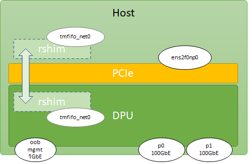
Please note that tmfifo_net0 interfaces are the virtual interfaces automatically created on top of the RShim connection between the host and the DPU, in both sides.
We can use these interfaces to install DPU software from the host, as an alternative to the out-of-band 1GbE physical port on the DPU.
|
Device |
Description |
Interfaces |
IP Addresses |
|---|---|---|---|
|
Master |
K8s master node and deployment node |
|
172.60.0.11/24 192.168.100.1/30 |
|
Worker1 |
K8s worker node 1 |
|
172.60.0.12/24 192.168.100.1/30 |
|
Worker2 |
K8s worker node 2 |
|
172.60.0.13/24 192.168.100.1/30 |
|
DPU |
Any of the used DPUs |
|
192.168.100.2/30 |
Switch and HBN configuration and connectivity:
|
Switch |
Description |
Router ID |
AS Number |
Links |
|---|---|---|---|---|
|
Leaf1 |
Leaf (TOR) switch 1 |
10.10.10.1/32 |
65101 |
To DPUs: To spines: To gateway node: |
|
Leaf2 |
Leaf (TOR) switch 2 |
10.10.10.2/32 |
65102 |
To DPUs: To spines: |
|
Spine1 |
Spine switch 1 |
10.10.10.101/32 |
65199 |
To leafs: |
|
Spine2 |
Spine switch 2 |
10.10.10.102/32 |
65199 |
|
|
Master HBN |
HBN on the master node DPU |
10.10.10.11/32 |
65111 |
To leafs: |
|
Worker 1 HBN |
HBN on Worker1 node DPU |
10.10.10.12/32 |
65112 |
|
|
Worker 2 HBN |
HBN on Worker2 node DPU |
10.10.10.13/32 |
65113 |
VTEPs configuration:
|
VTEP |
Interfaces |
VLAN |
VNI |
|---|---|---|---|
|
Leaf1 |
|
60 |
10060 |
|
HBN (Any) |
|
50 |
10050 |
|
|
60 |
10060 |
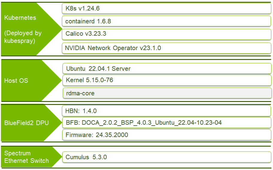
Software Stack Components
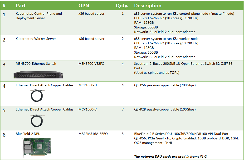
Bill of Materials
Deployment and Configuration
Configuring the Network Switches
-
The NVIDIA® SN3700 switches are installed with NVIDIA® Cumulus® Linux 5.3 OS
-
Each node is connected to two TOR switches over two 100Gb/s router ports (interfaces
swp1-3on the TOR switches) -
The TOR switches are connected to the two spine switches using router ports (interfaces
swp31-32on the TORs andswp1-2on the spines) -
In addition, a gateway node is connected through a VTEP to one of the TORs, providing external network access and Internet connectivity on the management network (VLAN60, interface
swp30on Leaf1)
Configure the switches using the following NVUE commands:
Host Preparation
-
Install Ubuntu 22.04 on the servers and make sure it is up-to-date:
Server Console
$ sudo apt update $ sudo apt upgrade $ sudo reboot -
To allow password-less
sudo, add the local user to the sudoers file on each host:Server Console
$ sudo vi /etc/sudoers #includedir /etc/sudoers.d #K8s cluster deployment user with sudo privileges without password user ALL=(ALL) NOPASSWD:ALL -
On the deployment node, generate an SSH key and copy it to each node. For example:
Deployment Node Console (Master node is used)
$ ssh-keygen Generating public/private rsa key pair. Enter file in which to save the key (/home/user/.ssh/id_rsa): Created directory '/home/user/.ssh'. Enter passphrase (empty for no passphrase): Enter same passphrase again: Your identification has been saved in /home/user/.ssh/id_rsa. Your public key has been saved in /home/user/.ssh/id_rsa.pub. The key fingerprint is: SHA256:PaZkvxV4K/h8q32zPWdZhG1VS0DSisAlehXVuiseLgA user@master The key's randomart image is: +---[RSA 2048]----+ | ...+oo+o..o| | .oo .o. o| | . .. . o +.| | E . o + . +| | . S = + o | | . o = + o .| | . o.o + o| | ..+.*. o+o| | oo*ooo.++| +----[SHA256]-----+ $ ssh-copy-id -i ~/.ssh/id_rsa user@10.10.0.1 /usr/bin/ssh-copy-id: INFO: Source of key(s) to be installed: "/home/user/.ssh/id_rsa.pub" The authenticity of host 10.10.0.1 (10.10.0.1)' can't be established. ECDSA key fingerprint is SHA256:uyglY5g0CgPNGDm+XKuSkFAbx0RLaPijpktANgXRlD8. Are you sure you want to continue connecting (yes/no)? yes /usr/bin/ssh-copy-id: INFO: attempting to log in with the new key(s), to filter out any that are already installed /usr/bin/ssh-copy-id: INFO: 1 key(s) remain to be installed -- if you are prompted now it is to install the new keys user@10.10.0.1's password: Number of key(s) added: 1 -
Now try logging into the machine, and verify that you can log in without a password.
Deploying the BFB
-
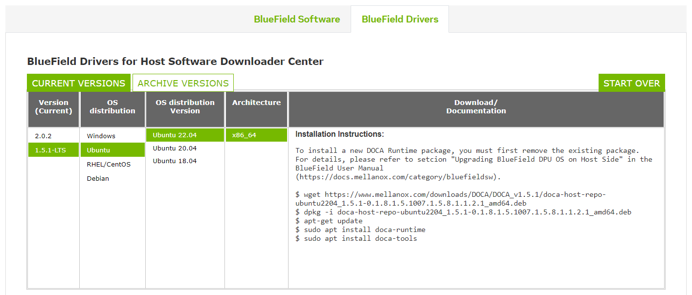
Download the DOCA host drivers packages form the DOCA webpage by scrolling down to the bottom of the page and selecting the relevant package. It will install all the necessary software to access and install the DPU from the host.
-
Install the DOCA host drivers package you downloaded:
Server Console
# wget https://www.mellanox.com/downloads/DOCA/DOCA_v1.5.1/doca-host-repo-ubuntu2204_1.5.1-0.1.8.1.5.1007.1.5.8.1.1.2.1_amd64.deb # dpkg -i doca-host-repo-ubuntu2204_1.5.1-0.1.8.1.5.1007.1.5.8.1.1.2.1_amd64.deb # apt-get update # apt install doca-runtime # apt install doca-tools -
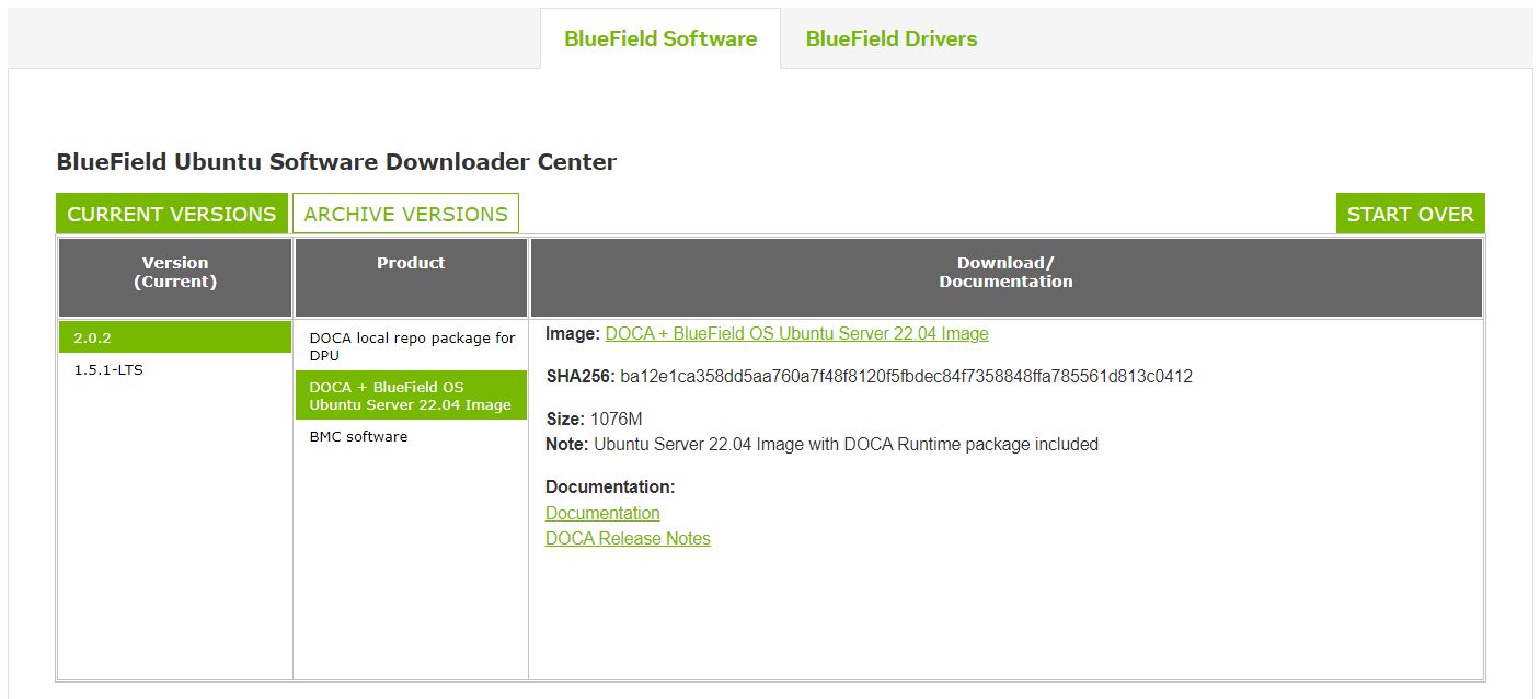
Download BFB 4.0.3 with DOCA 2.0.2v2:
-
Create the config file
bf.cfg:Server Console
# echo 'ENABLE_SFC_HBN=yes' > bf.cfg -
Install the BFB (the DPU's operating system image):
Server Console
# bfb-install -c bf.cfg -r rshim0 -b DOCA_2.0.2_BSP_4.0.3_Ubuntu_22.04-10.23-04.prod.bfb -
After the installation is complete, perform a full power cycle to the servers, allowing the DPU firmware to reboot and upgrade if needed.
-
After the servers return, assign IP addresses to the first interface of the DPU on each host using netplan. This is an example for the master node. The same should be done for the workers (172.60.0.12 and 172.60.0.13). Notice the default route to the gateway node (172.60.0.254) to provide external/Internet connectivity:
Server Console
# vi /etc/netplan/00-installer-config.yaml network: ethernets: eno1: dhcp4: true eno2: dhcp4: true eno3: dhcp4: true eno4: dhcp4: true ens2f0np0: dhcp4: false mtu: 9000 addresses: [172.60.0.11/24] nameservers: addresses: [8.8.8.8] search: [] routes: - to: default via: 172.60.0.254 ens2f1np1: dhcp4: false version: 2 -
Apply the settings:
Server Console
# netplan apply
Installing DOCA Container Configs Package
Log into the DPU in one of the following ways:
-
Using the OOB management interface (if connected and obtained an IP address over DHCP)
-
Using the built-in network interface over RShim (
tmfifo_net0)
This example uses the RShim option:
-
Use the following command to assign an IP address to the
tmfifo_net0interface:Server Console
# ip address add 192.168.100.1/30 dev tmfifo_net0When you first log into the DPU, use ubuntu/ubuntu as credentials.
-
You will be asked to modify the password:
Server Console
# ssh ubuntu@192.168.100.2 The authenticity of host '192.168.100.2 (192.168.100.2)' can't be established. ED25519 key fingerprint is SHA256:S2gzl4QzVUY0g3GRsl9VLi3tYHQdIe7oQ+8I8tr95c4. This key is not known by any other names Are you sure you want to continue connecting (yes/no/[fingerprint])? yes Warning: Permanently added '192.168.100.2' (ED25519) to the list of known hosts. ubuntu@192.168.100.2's password: You are required to change your password immediately (administrator enforced) Welcome to Ubuntu 20.04.5 LTS (GNU/Linux 5.4.0-1049-bluefield aarch64) * Documentation: https://help.ubuntu.com * Management: https://landscape.canonical.com * Support: https://ubuntu.com/advantage System information as of Mon Jan 16 12:53:57 UTC 2023 System load: 0.09 Usage of /: 6.7% of 58.00GB Memory usage: 13% Swap usage: 0% Processes: 485 Users logged in: 0 IPv4 address for docker0: 172.17.0.1 IPv4 address for mgmt: 127.0.0.1 IPv6 address for mgmt: ::1 IPv4 address for oob_net0: 10.10.7.37 IPv4 address for tmfifo_net0: 192.168.100.2 0 updates can be applied immediately. The programs included with the Ubuntu system are free software; the exact distribution terms for each program are described in the individual files in /usr/share/doc/*/copyright. Ubuntu comes with ABSOLUTELY NO WARRANTY, to the extent permitted by applicable law. WARNING: Your password has expired. You must change your password now and login again! Changing password for ubuntu. Current password: New password: Retype new password: passwd: password updated successfully Connection to 192.168.100.2 closed. -
Once you are logged into the DPU, download the DOCA container configs package and install it. This package includes the necessary scripts and configurations for activating the HBN container on the DPU:
DPU Console
# wget --content-disposition https://api.ngc.nvidia.com/v2/resources/nvidia/doca/doca_container_configs/versions/2.0.2v2/zip -O doca_container_configs_2.0.2v2.zip --no-check-certificate
# unzip -o doca_container_configs_2.0.2v2.zip -d doca_container_configs_2.0.2v2
# cd doca_container_configs_2.0.2v2/scripts/doca_hbn/1.4.0
# chmod +x hbn-dpu-setup.sh
# ./hbn-dpu-setup.sh
# cd ../../../configs/2.0.2/
# cp doca_hbn.yaml /etc/kubelet.d/
You will not be able to pull the zip file from the Internet if the DPU's out-of-band management interface is not used in your setup.
In this case, please pull it to the host and use
scpto copy it to the DPU over the RShim's network interface (tmfifo_net0).On the host console:
# wget --content-disposition https://api.ngc.nvidia.com/v2/resources/nvidia/doca/doca_container_configs/versions/2.0.2v2/zip -O doca_container_configs_2.0.2v2.zip --no-check-certificate # scp doca_container_configs_2.0.2v2.zip ubuntu@192.168.100.2:/home/ubuntu/ -
Reboot the DPU:
DPU Console
# reboot
Configuring HBN
After the DPU returns, it will run the "doca-hbn" container.
-
To find its ID (will appear in the first column under
CONTAINER), run:DPU Console
# crictl ps -
Connect to that container:
DPU Console
# crictl exec -it <container-id> bash -
Use the following NVUE commands to configure HBN (must be done on each DPU):
nv set bridge domain br_default vlan 50 vni 10050
nv set bridge domain br_default vlan 60 vni 10060
nv set evpn enable on
nv set interface lo ip address 10.10.10.11/32
nv set interface p0_sf,p1_sf link state up
nv set interface p0_sf,p1_sf,pf0hpf_sf,pf0vf0_sf,pf0vf10_sf,pf0vf11_sf,pf0vf12_sf,pf0vf13_sf,pf0vf1_sf,pf0vf2_sf,pf0vf3_sf,pf0vf4_sf,pf0vf5_sf,pf0vf6_sf,pf0vf7_sf,pf0vf8_sf,pf0vf9_sf type swp
nv set interface pf0vf0_sf,pf0vf10_sf,pf0vf11_sf,pf0vf12_sf,pf0vf13_sf,pf0vf1_sf,pf0vf2_sf,pf0vf3_sf,pf0vf4_sf,pf0vf5_sf,pf0vf6_sf,pf0vf7_sf,pf0vf8_sf,pf0vf9_sf bridge domain br_default access 50
nv set interface pf0hpf_sf,pf1hpf_sf bridge domain br_default access 60
nv set nve vxlan arp-nd-suppress on
nv set nve vxlan enable on
nv set nve vxlan source address 10.10.10.11
nv set vrf default router bgp peer-group underlay remote-as external
nv set vrf default router bgp neighbor p0_sf peer-group underlay
nv set vrf default router bgp neighbor p1_sf peer-group underlay
nv set router bgp autonomous-system 65111
nv set router bgp enable on
nv set router bgp router-id 10.10.10.11
nv set router policy route-map LOOPBACK rule 1 action permit
nv set router policy route-map LOOPBACK rule 1 match interface lo
nv set system global anycast-mac 44:38:39:BE:EF:AA
nv set vrf default router bgp address-family ipv4-unicast enable on
nv set vrf default router bgp address-family ipv4-unicast redistribute connected enable on
nv set vrf default router bgp address-family l2vpn-evpn enable on
nv set vrf default router bgp enable on
nv set vrf default router bgp neighbor p0_sf type unnumbered
nv set vrf default router bgp neighbor p1_sf type unnumbered
nv set vrf default router bgp path-selection multipath aspath-ignore on
nv set vrf default router bgp peer-group underlay address-family ipv4-unicast policy outbound route-map LOOPBACK
nv set vrf default router bgp peer-group underlay address-family ipv4-unicast soft-reconfiguration on
nv set vrf default router bgp peer-group underlay address-family l2vpn-evpn enable on
nv config apply -y
nv set bridge domain br_default vlan 50 vni 10050 nv set bridge domain br_default vlan 60 vni 10060 nv set evpn enable on nv set interface lo ip address 10.10.10.12/32 nv set interface p0_sf,p1_sf link state up nv set interface p0_sf,p1_sf,pf0hpf_sf,pf0vf0_sf,pf0vf10_sf,pf0vf11_sf,pf0vf12_sf,pf0vf13_sf,pf0vf1_sf,pf0vf2_sf,pf0vf3_sf,pf0vf4_sf,pf0vf5_sf,pf0vf6_sf,pf0vf7_sf,pf0vf8_sf,pf0vf9_sf type swp nv set interface pf0vf0_sf,pf0vf10_sf,pf0vf11_sf,pf0vf12_sf,pf0vf13_sf,pf0vf1_sf,pf0vf2_sf,pf0vf3_sf,pf0vf4_sf,pf0vf5_sf,pf0vf6_sf,pf0vf7_sf,pf0vf8_sf,pf0vf9_sf bridge domain br_default access 50 nv set interface pf0hpf_sf,pf1hpf_sf bridge domain br_default access 60 nv set nve vxlan arp-nd-suppress on nv set nve vxlan enable on nv set nve vxlan source address 10.10.10.12 nv set vrf default router bgp peer-group underlay remote-as external nv set vrf default router bgp neighbor p0_sf peer-group underlay nv set vrf default router bgp neighbor p1_sf peer-group underlay nv set router bgp autonomous-system 65112 nv set router bgp enable on nv set router bgp router-id 10.10.10.12 nv set router policy route-map LOOPBACK rule 1 action permit nv set router policy route-map LOOPBACK rule 1 match interface lo nv set system global anycast-mac 44:38:39:BE:EF:AA nv set vrf default router bgp address-family ipv4-unicast enable on nv set vrf default router bgp address-family ipv4-unicast redistribute connected enable on nv set vrf default router bgp address-family l2vpn-evpn enable on nv set vrf default router bgp enable on nv set vrf default router bgp neighbor p0_sf type unnumbered nv set vrf default router bgp neighbor p1_sf type unnumbered nv set vrf default router bgp path-selection multipath aspath-ignore on nv set vrf default router bgp peer-group underlay address-family ipv4-unicast policy outbound route-map LOOPBACK nv set vrf default router bgp peer-group underlay address-family ipv4-unicast soft-reconfiguration on nv set vrf default router bgp peer-group underlay address-family l2vpn-evpn enable onnv config apply -ynv set bridge domain br_default vlan 50 vni 10050 nv set bridge domain br_default vlan 60 vni 10060 nv set evpn enable on nv set interface lo ip address 10.10.10.13/32 nv set interface p0_sf,p1_sf link state up nv set interface p0_sf,p1_sf,pf0hpf_sf,pf0vf0_sf,pf0vf10_sf,pf0vf11_sf,pf0vf12_sf,pf0vf13_sf,pf0vf1_sf,pf0vf2_sf,pf0vf3_sf,pf0vf4_sf,pf0vf5_sf,pf0vf6_sf,pf0vf7_sf,pf0vf8_sf,pf0vf9_sf type swp nv set interface pf0vf0_sf,pf0vf10_sf,pf0vf11_sf,pf0vf12_sf,pf0vf13_sf,pf0vf1_sf,pf0vf2_sf,pf0vf3_sf,pf0vf4_sf,pf0vf5_sf,pf0vf6_sf,pf0vf7_sf,pf0vf8_sf,pf0vf9_sf bridge domain br_default access 50 nv set interface pf0hpf_sf,pf1hpf_sf bridge domain br_default access 60 nv set nve vxlan arp-nd-suppress on nv set nve vxlan enable on nv set nve vxlan source address 10.10.10.13 nv set vrf default router bgp peer-group underlay remote-as external nv set vrf default router bgp neighbor p0_sf peer-group underlay nv set vrf default router bgp neighbor p1_sf peer-group underlay nv set router bgp autonomous-system 65113 nv set router bgp enable on nv set router bgp router-id 10.10.10.13 nv set router policy route-map LOOPBACK rule 1 action permit nv set router policy route-map LOOPBACK rule 1 match interface lo nv set system global anycast-mac 44:38:39:BE:EF:AA nv set vrf default router bgp address-family ipv4-unicast enable on nv set vrf default router bgp address-family ipv4-unicast redistribute connected enable on nv set vrf default router bgp address-family l2vpn-evpn enable on nv set vrf default router bgp enable on nv set vrf default router bgp neighbor p0_sf type unnumbered nv set vrf default router bgp neighbor p1_sf type unnumbered nv set vrf default router bgp path-selection multipath aspath-ignore on nv set vrf default router bgp peer-group underlay address-family ipv4-unicast policy outbound route-map LOOPBACK nv set vrf default router bgp peer-group underlay address-family ipv4-unicast soft-reconfiguration on nv set vrf default router bgp peer-group underlay address-family l2vpn-evpn enable on nv config apply -y -
You can exit back to the host and validate the connectivity between the hosts by pinging them over the high-speed interface:
Server Console
$ ping 172.60.0.11
$ ping 172.60.0.12
$ ping 172.60.0.13
Deploying Kubernetes
Now we will deploy Kubernetes on the hosts using kubespray.
-
On the deployment node (master node can also be used as the deployment node), run:
Deployment Node Console (Master node is used)
$ cd ~ $ sudo apt -y install python3-pip jq $ wget https://github.com/kubernetes-sigs/kubespray/archive/refs/tags/v2.22.0.tar.gz $ tar -zxf v2.20.0.tar.gz $ cd kubespray-2.20.0 $ sudo pip3 install -r requirements.txt -
Create the initial cluster configuration for three nodes. We use the addresses we assigned to the DPU interface. The high-speed network is used for both the primary and the secondary network of our Kubernetes cluster:
Deployment Node Console (Master Node is used)
$ cp -rfp inventory/sample inventory/mycluster $ declare -a IPS=(172.60.0.11 172.60.0.12 172.60.0.13) $ CONFIG_FILE=inventory/mycluster/hosts.yaml python3 contrib/inventory_builder/inventory.py ${IPS[@]} -
Edit the hosts list as follows:
Deployment Node Console (Master Node is used)
$ vi inventory/mycluster/hosts.yaml all: hosts: master: ansible_host: 172.60.0.11 ip: 172.60.0.11 access_ip: 172.60.0.11 worker1: ansible_host: 172.60.0.12 ip: 172.60.0.12 access_ip: 172.60.0.12 worker2: ansible_host: 172.60.0.13 ip: 172.60.0.13 access_ip: 172.60.0.13 children: kube_control_plane: hosts: master: kube_node: hosts: worker1: worker2: etcd: hosts: master: k8s_cluster: children: kube_control_plane: kube_node: calico_rr: hosts: {} -
Edit the Calico configuration to use IP-in-IP:
Deployment Node Console (Master Node is used)
$ vi inventory/mycluster/group_vars/k8s_cluster/k8s-net-calico.yml calico_network_backend: "bird" calico_ipip_mode: "Always" calico_vxlan_mode: "Never" -
Deploy the cluster:
Deployment Node Console (Master Node is used)
$ ansible-playbook -i inventory/mycluster/hosts.yaml --become --become-user=root cluster.yml -
Label the worker nodes as workers:
Master Node Console
# kubectl label nodes worker1 node-role.kubernetes.io/worker=
# kubectl label nodes worker2 node-role.kubernetes.io/worker=
Installing the NVIDIA Network Operator
-
On the master node, install
helmand add the Mellanox repo:Master Node Console
# snap install helm --classic # helm repo add mellanox https://mellanox.github.io/network-operator && helm repo update -
Create the
values.yamlfile:# nano values.yaml nfd: enabled: true sriovNetworkOperator: enabled: true deployCR: true ofedDriver: deploy: false nvPeerDriver: deploy: false rdmaSharedDevicePlugin: deploy: false sriovDevicePlugin: deploy: false secondaryNetwork: deploy: true -
Install the operator:
Master Node Console
# helm install -f ./values.yaml -n network-operator --create-namespace --wait mellanox/network-operator --generate-name -
Validate the installation:
Master Node Console
# kubectl -n network-operator get pods -
Create the
policy.yamlfile:# nano policy.yaml apiVersion: sriovnetwork.openshift.io/v1 kind: SriovNetworkNodePolicy metadata: name: mlnxnic namespace: network-operator spec: nodeSelector: feature.node.kubernetes.io/custom-rdma.capable: "true" resourceName: mlnxnet priority: 99 mtu: 9000 numVfs: 16 nicSelector: pfNames: [ "ens2f0np0" ] deviceType: netdevice isRdma: true -
Apply it:
Master Node Console
# kubectl apply -f policy.yaml -
Create the
network.yamlfile:# nano network.yaml apiVersion: sriovnetwork.openshift.io/v1 kind: SriovNetwork metadata: name: mlnx-network namespace: network-operator spec: ipam: | { "datastore": "kubernetes", "kubernetes": { "kubeconfig": "/etc/cni/net.d/whereabouts.d/whereabouts.kubeconfig" }, "log_file": "/tmp/whereabouts.log", "log_level": "debug", "type": "whereabouts", "range": "172.50.0.0/24" } networkNamespace: default resourceName: mlnxnet -
Apply it:
Master Node Console
# kubectl apply -f network.yaml -
Wait a few minutes for the configuration to complete and then validate the network and its resources:
Master Node Console
# kubectl get network-attachment-definitions.k8s.cni.cncf.io
# kubectl get node worker1 -o json | jq '.status.allocatable'
# kubectl get node worker2 -o json | jq '.status.allocatable'
It may be necessary to perform a full power cycle on the servers if firmware configuration changes are required.
Validating the Deployment
Running Test Daemon-Set
On the master node:
-
Create the following
yamlfile:# nano testds.yaml apiVersion: apps/v1 kind: DaemonSet metadata: name: example-daemon labels: app: example-ds spec: selector: matchLabels: app: example-ds template: metadata: labels: app: example-ds annotations: k8s.v1.cni.cncf.io/networks: mlnx-network spec: containers: - image: ubuntu name: example-ds-pod securityContext: capabilities: add: [ "IPC_LOCK" ] resources: limits: memory: 16Gi cpu: 8 nvidia.com/mlnxnet: '1' requests: memory: 16Gi cpu: 8 nvidia.com/mlnxnet: '1' command: - sleep - inf -
Then create the deployment:
Master Node Console
# kubectl create -f testds.yaml
Running TCP Throughput Test
Now we will run a TCP throughput test on top of the high-speed secondary network between our pods running on different worker nodes.
Open an additional terminal window to the master node and connect to each of the pods:
-
Check the names of the pods:
Master Node Console
# kubectl get pods -
Connect to the desired pod:
Master Node Console
# kubectl exec -it <pod-name> -- bash -
Install and run
iperfTCP test between the two pods over the high-speed secondary network:First Pod Console
# apt update # apt install iproute2 iperf -y -
Check the IP address of the first pod on the high speed secondary network net1:
First Pod Console
# ip addr -
Run
iperfon it:First Pod Console
# iperf -s -
On the second pod, install
iperfand run it in client mode, connecting to the first pod:Second Pod Console
# apt update
# apt install iperf -y
# iperf -c <server-address> -P 10
Done!
Authors

|
Shachar Dor Shachar Dor joined the Solutions Lab team after working more than ten years as a software architect at NVIDIA Networking (previously Mellanox Technologies), where he was responsible for the architecture of network management products and solutions. Shachar's focus is on networking technologies, especially around fabric bring-up, configuration, monitoring, and life-cycle management. |
Last updated: