Created on April 3, 2023 by Vitaliy Razinkov
Scope
NVIDIA's hardware Accelerated Linux Bridge is a new solution that allows to significantly accelerate network performance and CPU overhead while using Linux bridge.
This Technology Preview document provides background and guidelines on how to evaluate the technology and its benefits for various use cases.
Abbreviations and Acronyms
|
Term |
Definition |
Term |
Definition |
|---|---|---|---|
|
CNI |
Container Network Interface |
LLDP |
Link Layer Discovery Protocol |
|
CR |
Custom Resources |
NFD |
Node Feature Discovery |
|
CRD |
Custom Resources Definition |
OCI |
Open Container Initiative |
|
CRI |
Container Runtime Interface |
PF |
Physical Function |
|
DHCP |
Dynamic Host Configuration Protocol |
QSG |
Quick Start Guide |
|
DNS |
Domain Name System |
RDG |
Reference Deployment Guide |
|
DP |
Device Plugin |
RoCE |
RDMA over Converged Ethernet |
|
DPDK |
Data Plane Development Kit |
SR-IOV |
Single Root Input Output Virtualization |
|
IPAM |
IP Address Management |
VF |
Virtual Function |
|
K8s |
Kubernetes |
VF-LAG |
Virtual Function over Link Aggregation |
Introduction
This document provides a step-by-step guide on how to install and configure hardware Accelerated Linux Bridge on a Kubernetes cluster with NVIDIA® ConnectX®-6 Dx SmartNIC to enhance the network performance and efficiency.
Linux bridge is a well know software component of the Linux OS, used to bridge between VMs and/or Containers. As it is implemented in software and executed on the main host CPU, it is not optimally performant and may utilize significant CPU resources. Legacy SRIOV on the other hand allows direct connectivity of the VM/Container to the NIC and by that allows for optimal performance and efficiency. However, Legacy SRIOV lacks many features that Linux bridge provides such as bonding or VLAN trunking.
Accelerated Linux bridge uses NVIDIA ASAP2 framework to allow the VM/container to still be connected with an SRIOV VF while the Linux bridge is used as the control plane. This way we get both the functionality of Linux bridge with the performance of SRIOV.
Accelerated Bridge CNI is used to enable accelerated Linux bridge in a K8s environment.
In this guide, we use the NVIDIA Network Operator and Accelerated Bridge CNI to enable high-performance secondary network for Kubernetes clusters. The NVIDIA Network Operator automates the installation and configuration of network components in K8s cluster. The Accelerated Bridge CNI provides a fast and efficient way for connecting pods to secondary network in a HW accelerated manner using VF-LAG.
The solution deployment is based on x86 standard servers for K8s worker nodes and K8s control plane node with the Ubuntu 22.04 operating system. Both Kubernetes management and secondary networks are handled by NVIDIA end-to-end Ethernet fabrics.
This guide applies to a greenfield deployment.
References
Solution Architecture
Key Components and Technologies
-
NVIDIA Spectrum SN3000 Open Ethernet Switches
NVIDIA® Spectrum®-2 SN3000 Ethernet switches are ideal for leaf and spine data center network solutions, allowing maximum flexibility with port speeds from 1GbE to 200GbE per port and port density that enables full-rack connectivity to any server at any speed.
SN3000 carries a whopping bidirectional switching capacity of up to 12.8Tb/s with a landmark 8.33Bpps packet processing rate. Purpose-built for the modern data center, SN3000 combines high performance, rich features, scalability, and visibility with flexible form factors.
-
NVIDIA Cumulus Linux
NVIDIA® Cumulus® Linux is the industry's most innovative open network operating system that allows you to automate, customize, and scale your data center network like no other.
-
NVIDIA® ConnectX®-6 Dx SmartNIC
ConnectX-6 Dx SmartNIC is the industry’s most secure and advanced cloud network interface card to accelerate mission-critical data-center applications, such as security, virtualization, SDN/NFV, big data, machine learning, and storage. The SmartNIC provides up to two ports of 100Gb/s or a single-port of 200Gb/s Ethernet connectivity and delivers the highest return on investment (ROI) of any smart network interface card. ConnectX-6 Dx is a member of NVIDIA's world-class, award-winning ConnectX series of network adapters powered by leading 50Gb/s (PAM4) and 25/10Gb/s (NRZ) SerDes technology and novel capabilities that accelerate cloud and data-center payloads.
-
NVIDIA LinkX Cables
The NVIDIA® LinkX® product family of cables and transceivers provides the industry’s most complete line of 10, 25, 40, 50, 100, 200, and 400GbE in Ethernet and 100, 200 and 400Gb/s InfiniBand products for Cloud, HPC, hyperscale, Enterprise, telco, storage and artificial intelligence, data center applications.
-
Kubernetes
Kubernetes is an open-source container orchestration platform for deployment automation, scaling, and management of containerized applications.
-
Kubespray
Kubespray is a composition ofAnsible
playbooks, inventory, provisioning tools, and domain knowledge for generic OS/Kubernetes clusters configuration management tasks and provides:
-
A highly available cluster
-
Composable attributes
-
Support for most popular Linux distributions
-
-
NVIDIA Network Operator
The NVIDIA Network Operator simplifies the provisioning and management of NVIDIA networking resources in a Kubernetes cluster. The operator automatically installs the required host networking software - bringing together all the needed components to provide high-speed network connectivity. These components include the NVIDIA networking driver, Kubernetes device plugin, CNI plugins, IP address management (IPAM) plugin and others. The NVIDIA Network Operator works in conjunction with the NVIDIA GPU Operator to deliver high-throughput, low-latency networking for scale-out, GPU computing clusters.
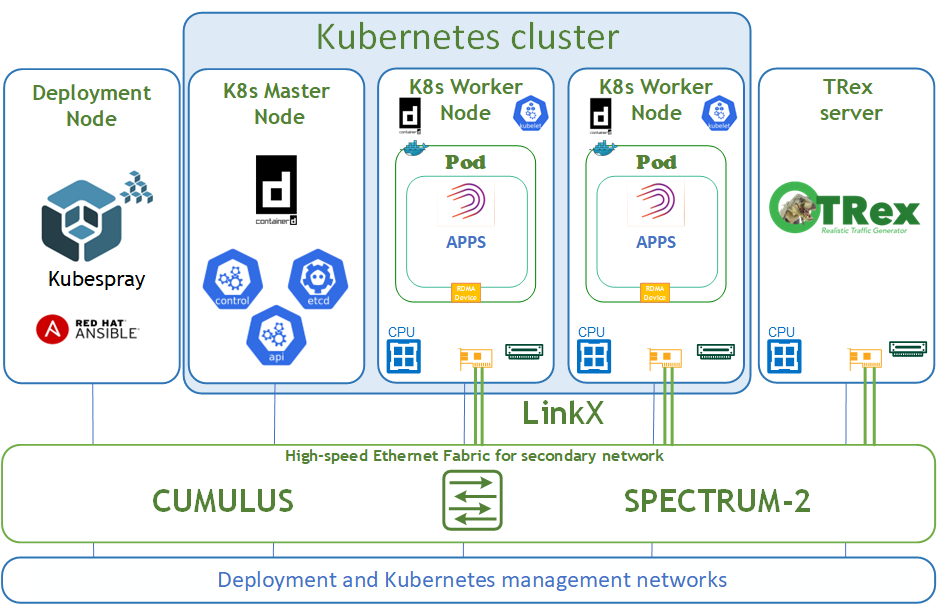
Logical Design
The logical design includes the following parts:
-
Deployment node running Kubespray that deploys a Kubernetes cluster
-
K8s Master node running all Kubernetes management components
-
K8s Worker nodes with NVIDIA ConnectsX-6 Dx adapters
-
TRex server for DPDK traffic emulation
-
High-speed Ethernet fabric (secondary K8s network)
-
Deployment and K8s management networks
Network / Fabric Design
This guide shows the simplest deployment which is based on one switch for K8s deployment and management networks and one switch for the high-speed Ethernet network.
The high-speed network is a secondary network for the Kubernetes cluster and requires an L2 network topology.
The Kubernetes Management network and DNS/DHCP network services are parts of the IT infrastructure and are beyond the scope of this document.
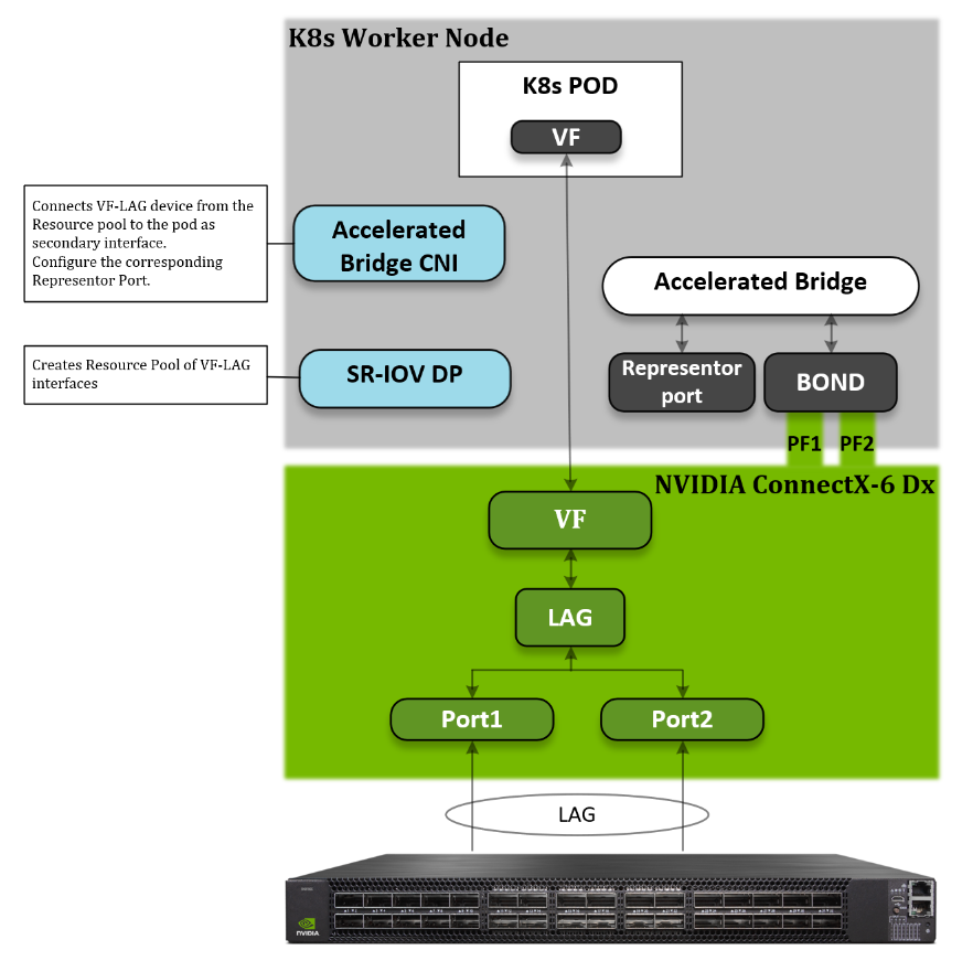
Host Design
The following diagram shows the logical design of a K8s Worker Node. The host binds the two physical functions (PFs) network interfaces from the same NIC. With NVIDIA VF-LAG technology, the VFs of these two ports will be binded as well using the same bond mode applies on the physical ports. For example: If BOND is configured in LACP mode, then all VF-LAG interfaces have the same configuration.
To use VF-LAG, the NIC must be in SR-IOV switchdev mode and we will use the Linux bridge as the SR-IOV switchdev control plane. We use a K8s SR-IOV device plugin in “Hostdev mode” and Accelerated Bridge CNI to configure a secondary POD interface.
SR-IOV Device Plugin is responsible for providing a VF-LAG interface for a pod. The Accelerated Bridge CNI plumbs the VF-LAG interface into a pod and configures the Representor port on the Accelerated Bridge.
Software Stack Components
The following software components have been used to deploy the system:
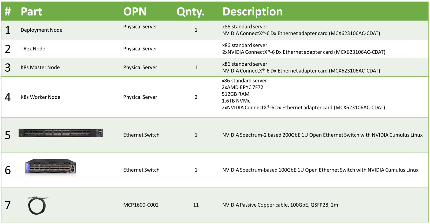
Bill of Materials
The following table lists the hardware components used for the setup.
Deployment and Configuration
Network / Fabric
Network Configuration
Below are the server names along with their relevant network configurations.
|
|
|
IP and NICS |
|
|
High-speed network
|
Management network 100GbE |
||
|
Deployment node |
depserver |
|
ens4f0: DHCP
|
|
Master node |
node1 |
|
ens4f0: DHCP
|
|
Worker node |
node2 |
bond0: no IP set |
ens4f0: DHCP
|
|
Worker node |
node3 |
bond0: no IP set |
ens4f0: DHCP
|
|
TRex server |
node4 |
ens2f0: no IP set ens2f1: no IP set |
ens4f0: DHCP 192.168.100.50 |
|
High-speed switch |
switch01 |
|
mgmt0: From DHCP
|
bond0 high-speed network interface does not require additional configuration.
Wiring
On each K8s Worker Node, both ports of the NVIDIA NIC are wired to an NVIDIA switch in a high-performance fabric using NVIDIA® LinkX® DAC cables. Also, the management port of all nodes is wired to an NVIDIA SN2100 Ethernet switch.
The following figure illustrates the required wiring for building a K8s cluster.
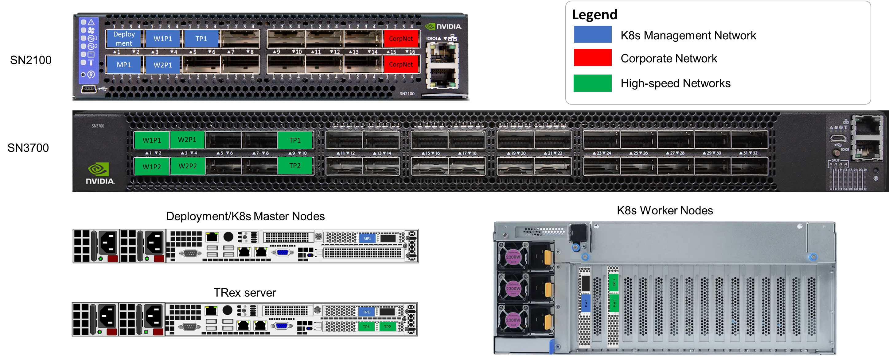
Server remote management and switch management wiring over a 1GbE network are beyond the scope of this guide.
Fabric Configuration
This solution was deployed with Cumulus Linux v5.4 network operating system.
Check that your Cumulus Linux switch has passed its initial configuration stages (see the Quick-Start Guide for version 5.4 for more information).
Fabric configuration steps:
-
As Administrator, enable all physical ports.
-
Create bonds.
-
Create a bridge and configure it.
-
Create VLANs.
-
Add VLANs to bridge.
-
Commit configuration.
Switch configuration steps:
nv set interface swp1-32
nv set system hostname switch01
nv config apply
nv set interface bond1 bond member swp1-2
nv set interface bond2 bond member swp3-4
nv set interface swp5-32 bridge domain br_default
nv set interface bond1-2 bridge domain br_default
nv set bridge domain br_default vlan 2001-2005
nv config apply -y
nv config save
To view link status, use the "nv show interface" command.
Node Configuration
General Prerequisites:
-
Hardware
All the K8s Worker nodes have the same hardware specification and ConnectX-6 Dx NIC installed in the same PCIe slot. -
Host BIOS
Verify that an SR-IOV supported server platform is being used and review the BIOS settings in the server platform vendor documentation to enable SR-IOV in the BIOS. -
Host OS
Ubuntu Server 22.04 operating system should be installed on all servers with OpenSSH server packages. -
Experience with Kubernetes
Familiarization with the Kubernetes Cluster architecture is essential.
Host OS Prerequisites
Make sure that Ubuntu Server 22.04 operating system is installed on all servers with OpenSSH server packages and create a non-root depuser account with sudo privileges without a password.
Update the Ubuntu software packages and install a specific Linux kernel by running the following commands:
$ sudo apt-get update
$ sudo apt-get upgrade -y
$ sudo apt install -y lldpd rdma-core linux-image-5.19.0-32-generic linux-modules-extra-5.19.0-32-generic
$ sudo reboot
In this solution we added the following line to the EOF /etc/sudoers:
$ sudo vim /etc/sudoers

#includedir /etc/sudoers.d

#K8s cluster deployment user with sudo privileges without password
depuser ALL=(ALL) NOPASSWD:ALL
NIC Firmware Upgrade
It is recommended to upgrade NIC firmware on all nodes to the latest version released.
Download the mlxup firmware update and query utility to each Worker node and update NIC firmware.
The most recent version of mlxup can be downloaded from the official download page.
The utility execution requires sudo privileges:
# chmod +x mlxup
# ./mlxup -online -u -y
Netplan Configuration
This step should be applied to all K8s Worker nodes.
Netplan is the network configuration abstraction renderer used for easily configuring networking on a Linux system. Configuration is performed by creating a simple YAML description of the required network interfaces and what each interface should be configured to do. Below is a YAML file example which is required for our deployment.
The default configuration file for Netplan is /etc/netplan/00-installer-config.yaml.
In our deployment, NICs enp57s0f0np0 and enp57s0f1np1 were used as part of Linux Accelerated Bridge.
# This is the network config written by 'subiquity'
network:
  version: 2
  ethernets:
    enp57s0f0np0:
      dhcp4: false
      mtu: 9216
      embedded-switch-mode: switchdev
      virtual-function-count: 8
      delay-virtual-functions-rebind: true
    enp57s0f1np1:
      dhcp4: false
      mtu: 9216
      embedded-switch-mode: switchdev
      virtual-function-count: 8
      delay-virtual-functions-rebind: true
    enp64s0f0np0:
      dhcp4: true
      dhcp-identifier: mac
    enp64s0f0np1:
      dhcp4: false
  bonds:
    bond0:
      dhcp4: false
      mtu: 9216
      interfaces:
        - enp57s0f0np0
        - enp57s0f1np1
      parameters:
        mode: 802.3ad
        transmit-hash-policy: layer3+4
        lacp-rate: fast
        mii-monitor-interval: 100
Apply Netplan configuration.
# netplan apply
Reboot is required to apply the configuration.
After the server is started, please review the dmesg log file, which should include lines as shown below. These lines indicate that VF-LAG is activated properly.
[   48.305593] mlx5_core 0000:39:00.1: E-Switch: Enable: mode(OFFLOADS), nvfs(8), active vports(9)
[   49.195354] mlx5_core 0000:39:00.0: lag map active ports: 1
[   49.195361] mlx5_core 0000:39:00.0: shared_fdb:1 mode:hash
[   49.321334] mlx5_core 0000:39:00.0: Operation mode is single FDB
[   49.733106] mlx5_core 0000:39:00.0: lag map active ports: 1, 2
Manage HugePages
This step should be applied to all K8s Worker nodes.
Kubernetes supports the allocation and consumption of pre-allocated HugePages by applications in a Pod. The nodes will automatically discover and report all HugePages resources as schedulable resources. For additional information about K8s HugePages management, please see here. For additional information on the kernel’s command-line parameters and parameter descriptions please see here.
To allocate, HugePages needs to modify the GRUB_CMDLINE_LINUX_DEFAULT parameter in /etc/default/grub. GRUB_CMDLINE_LINUX_DEFAULT parameters for our K8s Worker nodes are provided below:
...

GRUB_CMDLINE_LINUX_DEFAULT="iommu=pt numa_balancing=disable processor.max_cstate=0 default_hugepagesz=1G hugepagesz=1G hugepages=64 isolcpus=2-45 nohz_full=2-45 rcu_nocbs=2-45"

...
Run update-grub to apply the config to grub and reboot server:
# update-grub
# reboot
Linux Bridge Configuration
This step should be applied to all K8s Worker nodes.
Linux Bridge is a standard interface widely supported by various Linux distributions. Basic functionality of the Linux Bridge is implemented in the upstream Linux kernel. Linux bond support is also included in the upstream Linux kernel. Specific Linux Bridge features are implemented in the following upstream Linux kernels:
-
Bridge offload with VLAN - 5.14
-
Bridge LAG support - 5.15
-
Bridge spoof check - 5.16
-
Bridge QinQ support - 6.0
Accelerated Linux Bridge is an innovative technology that aims to replace legacy SR-IOV. It provides a kernel-space-only solution for basic connectivity between the physical uplink and the VFs, without relying on user-space components such as Open vSwitch. This solution can be enhanced with additional features (LAG/Bond, VGT+, etc).
Now we create and enable the systemd service to start the Accelerated Bridge on system startup.
Accelerated Linux Bridge in our deployment is created by a standard service - /etc/systemd/system/ab-configuration.service.
[Unit]
Description=Configures Linux Bridge for using by K8s AB CNI
Wants=sys-devices-virtual-net-bond0.device
Before=sys-devices-virtual-net-bond0.device

[Service]
Type=oneshot
ExecStart=/usr/local/bin/configure-ab.sh
StandardOutput=journal+console
StandardError=journal+console

[Install]
WantedBy=online.target
Script execution file - /usr/local/bin/configure-ab.sh.
#!/bin/bash
set -eux

#Create and configure bridge - accelbr for using it by K8s AB CNI

ip link add name accelbr type bridge
ip link set accelbr mtu 9216
ip link set bond0 master accelbr
ip link set accelbr up
ip link set accelbr type bridge ageing_time 200
ip link set accelbr type bridge vlan_filtering 1
ip link set accelbr type bridge fdb_flush
Apply configuration.
# chmod +x /usr/local/bin/configure-ab.sh
# systemctl daemon-reload
# systemctl enable ab-configuration.service
Server reboot is required for proper service activation.
K8s Cluster Deployment and Configuration
The Kubernetes cluster in this solution is installed using Kubespray with a non-root depuser account from the Deployment node.
SSH Private Key and SSH Passwordless Login
Log into the Deployment node as a deployment user (in this case, depuser) and create an SSH private key for configuring the passwordless authentication on your computer by running the following commands:
$ ssh-keygen
Generating public/private rsa key pair.
Enter file in which to save the key (/home/depuser/.ssh/id_rsa):
Created directory '/home/depuser/.ssh'.
Enter passphrase (empty for no passphrase):
Enter same passphrase again:
Your identification has been saved in /home/depuser/.ssh/id_rsa
Your public key has been saved in /home/depuser/.ssh/id_rsa.pub
The key fingerprint is:
SHA256:IfcjdT/spXVHVd3n6wm1OmaWUXGuHnPmvqoXZ6WZYl0 depuser@depserver
The key's randomart image is:
+---[RSA 3072]----+
|                *|
|               .*|
|      . o . .  o=|
|       o + . o +E|
|        S o  .**O|
|         . .o=OX=|
|           . o%*.|
|             O.o.|
|           .*.ooo|
+----[SHA256]-----+
Copy your SSH private key, such as ~/.ssh/id_rsa, to all nodes in the deployment by running the following command (example):
$ ssh-copy-id depuser@192.168.100.25
/usr/bin/ssh-copy-id: INFO: Source of key(s) to be installed: "/home/depuser/.ssh/id_rsa.pub"
The authenticity of host '192.168.100.25 (192.168.100.25)' can't be established.
ECDSA key fingerprint is SHA256:6nhUgRlt9gY2Y2ofukUqE0ltH+derQuLsI39dFHe0Ag.
Are you sure you want to continue connecting (yes/no/[fingerprint])? yes
/usr/bin/ssh-copy-id: INFO: attempting to log in with the new key(s), to filter out any that are already installed
/usr/bin/ssh-copy-id: INFO: 1 key(s) remain to be installed -- if you are prompted now it is to install the new keys
depuser@192.168.100.25's password:

Number of key(s) added: 1

Now try logging into the machine, with:   "ssh 'depuser@192.168.100.25'"
and check to make sure that only the key(s) you wanted were added.
Verify that you have passwordless SSH connectivity to all nodes in your deployment by running the following command (example):
$ ssh depuser@192.168.100.25
Kubespray Deployment and Configuration
General Setting
To install dependencies for running Kubespray with Ansible on the deployment node, run following commands:
$ cd ~
$ sudo apt -y install python3-pip jq
$ wget https://github.com/kubernetes-sigs/kubespray/archive/refs/tags/v2.21.0.tar.gz
$ tar zxf v2.21.0.tar.gz
# cd kubespray-2.21.0/
$ sudo pip3 install -r requirements.txt
The default folder for subsequent commands is ~/kubespray-2.21.0.
Deployment Customization
Create a new cluster configuration and host configuration file.
Replace the IP addresses below with your nodes' IP addresses:
$ cp -rfp inventory/sample inventory/mycluster
$ declare -a IPS=(192.168.100.25 192.168.100.34 192.168.100.39)
$ CONFIG_FILE=inventory/mycluster/hosts.yaml python3 contrib/inventory_builder/inventory.py ${IPS[@]}
As a result, the inventory/mycluster/hosts.yaml file will be created.
Review and change the host configuration in the file. Below is an example for this deployment.
all:
  hosts:
    node1:
      ansible_host: 192.168.100.25
      ip: 192.168.100.25
      access_ip: 192.168.100.25
    node2:
      ansible_host: 192.168.100.34
      ip: 192.168.100.34
      access_ip: 192.168.100.34
      node_labels:
        "node-role.kubernetes.io/worker": ""
    node3:
      ansible_host: 192.168.100.39
      ip: 192.168.100.39
      access_ip: 192.168.100.39
      node_labels:
        "node-role.kubernetes.io/worker": ""
  children:
    kube_control_plane:
      hosts:
        node1:
    kube_node:
      hosts:
        node2:
        node3:
    etcd:
      hosts:
        node1:
    k8s_cluster:
      children:
        kube_control_plane:
        kube_node:
Review and change cluster installation parameters in the file inventory/mycluster/group_vars/k8s-cluster/k8s-cluster.yml.
In this file, set a default Kubernetes CNI by setting the desired kube_network_plugin value: flannel (default: calico).
...

# Choose network plugin (cilium, calico, contiv, weave or flannel. Use cni for generic cni plugin)
# Can also be set to 'cloud', which lets the cloud provider setup appropriate routing
kube_network_plugin: flannel

# Setting multi_networking to true will install Multus: https://github.com/intel/multus-cni
kube_network_plugin_multus: false

...
Deploying the Cluster Using KubeSpray Ansible Playbook
Run the following line to start the deployment process:
$ ansible-playbook -i inventory/mycluster/hosts.yaml --become --become-user=root cluster.yml
It takes a while for this deployment to complete. Make sure no errors are encountered.
If the deployment is successful, lines such as in the following should be displayed.
... PLAY RECAP ***********************************************************************************************************************************************************************************

localhost                  : ok=3    changed=0    unreachable=0    failed=0    skipped=0    rescued=0    ignored=0
node1                      : ok=674  changed=114  unreachable=0    failed=0    skipped=1195 rescued=0    ignored=5
node2                      : ok=482  changed=68   unreachable=0    failed=0    skipped=707  rescued=0    ignored=1
node3                      : ok=487  changed=92   unreachable=0    failed=0    skipped=712  rescued=0    ignored=1

Sunday 12 March 2023  12:20:05 +0000 (0:00:00.115)       0:09:56.967 *****
===============================================================================
kubernetes/kubeadm : Join to cluster ------------------------------------------------------------------------------------------------------------------------------------------------- 30.36s
kubernetes/control-plane : kubeadm | Initialize first master ------------------------------------------------------------------------------------------------------------------------- 13.83s
download : download_container | Download image if required ---------------------------------------------------------------------------------------------------------------------------- 9.79s
kubernetes-apps/ansible : Kubernetes Apps | Start Resources --------------------------------------------------------------------------------------------------------------------------- 8.39s
kubernetes/preinstall : Preinstall | wait for the apiserver to be running ------------------------------------------------------------------------------------------------------------- 7.67s
kubernetes-apps/ansible : Kubernetes Apps | Lay Down CoreDNS templates ---------------------------------------------------------------------------------------------------------------- 7.29s
download : download_container | Download image if required ---------------------------------------------------------------------------------------------------------------------------- 6.89s
etcd : reload etcd -------------------------------------------------------------------------------------------------------------------------------------------------------------------- 6.15s
container-engine/validate-container-engine : Populate service facts ------------------------------------------------------------------------------------------------------------------- 5.89s
download : download_container | Download image if required ---------------------------------------------------------------------------------------------------------------------------- 5.66s
download : download_file | Download item ---------------------------------------------------------------------------------------------------------------------------------------------- 5.58s
download : download_container | Download image if required ---------------------------------------------------------------------------------------------------------------------------- 5.51s
etcd : Configure | Check if etcd cluster is healthy ----------------------------------------------------------------------------------------------------------------------------------- 5.46s
download : download_container | Download image if required ---------------------------------------------------------------------------------------------------------------------------- 5.45s
kubernetes-apps/network_plugin/flannel : Flannel | Wait for flannel subnet.env file presence ------------------------------------------------------------------------------------------ 5.45s
download : download_container | Download image if required ---------------------------------------------------------------------------------------------------------------------------- 5.28s
download : download_container | Download image if required ---------------------------------------------------------------------------------------------------------------------------- 5.13s
container-engine/containerd : containerd | Unpack containerd archive ------------------------------------------------------------------------------------------------------------------ 5.01s
container-engine/nerdctl : download_file | Download item ------------------------------------------------------------------------------------------------------------------------------ 4.91s
etcd : Configure | Ensure etcd is running --------------------------------------------------------------------------------------------------------------------------------------------- 4.90s
K8S Cluster Deployment Verification
The following is an output example of K8s cluster deployment information using the Flannel CNI plugin.
To ensure that the Kubernetes cluster is installed correctly, run the following commands:
# kubectl get nodes -o wide
NAME        STATUS   ROLES           AGE   VERSION   INTERNAL-IP      EXTERNAL-IP   OS-IMAGE             KERNEL-VERSION         CONTAINER-RUNTIME
node1       Ready    control-plane    1d   v1.25.6   192.168.100.25   <none>        Ubuntu 22.04.1 LTS   5.19.0-32-generic      containerd://1.6.15
node2       Ready    worker           1d   v1.25.6   192.168.100.34   <none>        Ubuntu 22.04.2 LTS   5.19.0-32-generic      containerd://1.6.15
node3       Ready    worker           1d   v1.25.6   192.168.100.39   <none>        Ubuntu 22.04.2 LTS   5.19.0-32-generic      containerd://1.6.15

# kubectl -n kube-system get pods -o wide
NAME                                         READY   STATUS    RESTARTS      AGE   IP               NODE        NOMINATED NODE   READINESS GATES
coredns-588bb58b94-8wccf                     1/1     Running   0              1d   10.233.64.2      node2       <none>           <none>
coredns-588bb58b94-zr62x                     1/1     Running   0              1d   10.233.67.89     node3       <none>           <none>
dns-autoscaler-5b9959d7fc-9rc8r              1/1     Running   0              1d   10.233.64.3      node1       <none>           <none>
kube-accelerated-bridge-cni-ds-amd64-bskjh   1/1     Running   0              1d   192.168.100.39   node3       <none>           <none>
kube-accelerated-bridge-cni-ds-amd64-lnhrm   1/1     Running   0              1d   192.168.100.34   node2       <none>           <none>
kube-apiserver-node1                         1/1     Running   0              1d   192.168.100.25   node1       <none>           <none>
kube-controller-manager-node1                1/1     Running   0              1d   192.168.100.25   node1       <none>           <none>
kube-flannel-6g2kj                           1/1     Running   0              1d   192.168.100.34   node2       <none>           <none>
kube-flannel-9xnbz                           1/1     Running   0              1d   192.168.100.25   node1       <none>           <none>
kube-flannel-skdnh                           1/1     Running   0              1d   192.168.100.39   node3       <none>           <none>
kube-proxy-rxvnj                             1/1     Running   0              1d   192.168.100.34   node2       <none>           <none>
kube-proxy-wgjjq                             1/1     Running   0              1d   192.168.100.25   node1       <none>           <none>
kube-proxy-wn8xj                             1/1     Running   0              1d   192.168.100.39   node3       <none>           <none>
kube-scheduler-node1                         1/1     Running   0              1d   192.168.100.25   node1       <none>           <none>
nginx-proxy-node2                            1/1     Running   0              1d   192.168.100.34   node2       <none>           <none>
nginx-proxy-node3                            1/1     Running   0              1d   192.168.100.39   node3       <none>           <none>
nodelocaldns-72zsq                           1/1     Running   0              1d   192.168.100.25   node1       <none>           <none>
nodelocaldns-9db7z                           1/1     Running   0              1d   192.168.100.39   node3       <none>           <none>
nodelocaldns-nt94k                           1/1     Running   0              1d   192.168.100.34   node2       <none>           <none>
NVIDIA Network Operator Installation for K8s Cluster
NVIDIA Network Operator leverages Kubernetes CRDs and an Operator SDK to manage networking-related components in order to enable fast networking and RDMA for workloads in K8s cluster. The Fast Network is a secondary network of the K8s cluster for applications that require high bandwidth or low latency.
To make it work, several components need to be provisioned and configured. All operator configuration and installation steps should be performed from the K8s Master node with the root user account.
Prerequisites
Install Helm.
# snap install helm --classic
Deployment
Add the NVIDIA Network Operator Helm repository.
# helm repo add mellanox https://mellanox.github.io/network-operator
# helm repo update
Create the values.yaml file in user's home folder (example).
nfd:
  enabled: true

sriovNetworkOperator:
  enabled: false

ofedDriver:
  deploy: false
nvPeerDriver:
  deploy: false
rdmaSharedDevicePlugin:
  deploy: false

sriovDevicePlugin:
  deploy: true
  resources:
    - name: vflag
      pfNames: ["enp57s0f0np0"]
      devices: ["101e"]

deployCR: true
secondaryNetwork:
  deploy: true
  cniPlugins:
    deploy: true
  multus:
    deploy: true
  ipamPlugin:
    deploy: true
Deploy the operator.
# helm install -f ./values.yaml -n network-operator --create-namespace --wait mellanox/network-operator --generate-name
NAME: network-operator-1676546312
LAST DEPLOYED: Mon Mar 13 11:18:32 2023
NAMESPACE: network-operator
STATUS: deployed
REVISION: 1
TEST SUITE: None
NOTES:
Get Network Operator deployed resources by running the following commands:

$ kubectl -n network-operator get pods
To ensure that the Operator is deployed correctly, run the commands below.
# kubectl -n network-operator get pods -o wide
NAME                                                              READY   STATUS              RESTARTS   AGE   IP               NODE        NOMINATED NODE   READINESS GATES
cni-plugins-ds-vxzmq                                              1/1     Running             0          18s   192.168.100.34   node2       <none>           <none>
cni-plugins-ds-z526k                                              1/1     Running             0          18s   192.168.100.39   node3       <none>           <none>
kube-multus-ds-5lznw                                              1/1     Running             0          18s   192.168.100.39   node3       <none>           <none>
kube-multus-ds-jds9c                                              1/1     Running             0          18s   192.168.100.34   node2       <none>           <none>
network-operator-1676546312-85ccdf64cf-zmr65                      1/1     Running             0          43s   10.233.64.5      node1       <none>           <none>
network-operator-1676546312-node-feature-discovery-master-gnwp5   1/1     Running             0          43s   10.233.64.6      node1       <none>           <none>
network-operator-1676546312-node-feature-discovery-worker-8tbdp   1/1     Running             0          43s   10.233.64.4      node1       <none>           <none>
network-operator-1676546312-node-feature-discovery-worker-k8gdk   1/1     Running             0          43s   10.233.65.3      node2       <none>           <none>
network-operator-1676546312-node-feature-discovery-worker-ss4dx   1/1     Running             0          43s   10.233.66.2      node3       <none>           <none>
sriov-device-plugin-5p2xt                                         0/1     ContainerCreating   0          18s   192.168.100.39   node3       <none>           <none>
sriov-device-plugin-n9pjp                                         0/1     ContainerCreating   0          18s   192.168.100.34   node2       <none>           <none>
whereabouts-2dng2                                                 0/1     ContainerCreating   0          18s   192.168.100.34   node2       <none>           <none>
whereabouts-xjhq6                                                 0/1     ContainerCreating   0          18s   192.168.100.39   node3       <none>           <none>
Check worker node resources.
# kubectl describe nodes node2
...

Addresses:
  InternalIP:  192.168.100.34
  Hostname:    node2
Capacity:
  cpu:                48
  ephemeral-storage:  459283568Ki
  hugepages-1Gi:      64Gi
  hugepages-2Mi:      0
  memory:             528157216Ki
  nvidia.com/vflag:   8
  pods:               110
Allocatable:
  cpu:                46
  ephemeral-storage:  421128251920
  hugepages-1Gi:      64Gi
  hugepages-2Mi:      0
  memory:             456751648Ki
  nvidia.com/vflag:   8
  pods:               110

...
Deploy Accelerated Bridge CNI Plugin
This plugin enables Linux Bridge with hardware offloading in containers and orchestrators in Kubernetes. The Accelerated Bridge CNI plugin requires a NIC with support for SR-IOV technology with VFs in switchdev mode and support of Linux Bridge offloading.
-
Deploy CNI plugin using the following YAML files.
# kubectl apply -f https://raw.githubusercontent.com/k8snetworkplumbingwg/accelerated-bridge-cni/master/images/accelerated-bridge-cni-daemonset.yamlBy default, the plugin will be deployed in kube-system K8s namespace.
# kubectl -n kube-system get pod -o wide | grep bridge kube-accelerated-bridge-cni-ds-amd64-bskjh 1/1 Running 0 43s 192.168.100.39 node3 <none> <none> kube-accelerated-bridge-cni-ds-amd64-lnhrm 1/1 Running 0 43s 192.168.100.34 node2 <none> <none> -
Create a Linux Bridge network attachment definition and deploy it.
You need to create a Linux Bridge network attachment definition in order to connect the POD to secondary networks. Accelerated Bridge CNI supports a few deployment modes: VLAN or TRUNK.
Below is an example with VLAN mode - net-vst.yaml.apiVersion: "k8s.cni.cncf.io/v1" kind: NetworkAttachmentDefinition metadata: name: net-vst annotations: k8s.v1.cni.cncf.io/resourceName: nvidia.com/vflag spec: config: '{ "type": "accelerated-bridge", "cniVersion": "0.3.1", "name": "net-vst", "vlan": 2001, "mtu": 9000, "setUplinkVlan": true, "bridge": "accelbr", "capabilities": {"CNIDeviceInfoFile": true}, "ipam": { "datastore": "kubernetes", "kubernetes": { "kubeconfig": "/etc/cni/net.d/whereabouts.d/whereabouts.kubeconfig" }, "log_file": "/tmp/whereabouts.log", "log_level": "debug", "type": "whereabouts", "range": "192.168.101.0/24" } }'# kubectl create -f net-vst.yaml -
Check if the network attachment definition has deployed successfully.
# kubectl get network-attachment-definitions.k8s.cni.cncf.io
NAME      AGE
net-vst    1m
Enable CPU and Topology Management
CPU Manager manages groups of CPUs and constrains workloads to specific CPUs.
CPU Manager is useful for workloads that have some of the following attributes:
-
Require as much CPU time as possible
-
Are sensitive to processor cache misses
-
Are low-latency network applications
-
Coordinate with other processes and benefit from sharing a single processor cache
Topology Manager uses topology information from collected hints to decide if a POD can be accepted or rejected on a node, based on the configured Topology Manager policy and POD resources requested. In order to obtain the best performance, optimizations related to CPU isolation and memory and device locality are required.
Topology Manager is useful for workloads that use hardware accelerators to support latency-critical execution and high throughput parallel computation.
To use Topology Manager, CPU Manager with static policy must be used.
For additional information, refer to Control Topology Management Policies on a node and Control Topology Management Policies on a node.
In order to enable CPU Manager and Topology Manager, add the following lines to the kubelet configuration file /etc/kubernetes/kubelet-config.yaml on each K8s Worker node.
...
systemReserved:
  cpu: "2"
  memory: "4Gi"
  ephemeral-storage: "2Gi"
reservedSystemCpus: 0,1,46,47
cpuManagerPolicy: static
cpuManagerReconcilePeriod: 10s
topologyManagerPolicy: single-numa-node
featureGates:
  CPUManager: true
  TopologyManager: true
Due to changes in cpuManagerPolicy, remove /var/lib/kubelet/cpu_manager_state and restart the kubelet service on each of the affected K8s Worker nodes.
# rm -f /var/lib/kubelet/cpu_manager_state
# service kubelet restart
Application
For application tests, a container image based on Ubuntu 22.04 with inbox packages has been used. A Dockerfile example of container image creation is provided below.
FROM ubuntu:22.04
# Ubuntu 22.04 container with inbox Mellanox drivers

# LABEL about the custom image
LABEL maintainer=vitaliyra@nvidia.com
LABEL description="This is custom Container Image with inbox perftest package."

WORKDIR /tmp/
ENV DEBIAN_FRONTEND=noninteractive
RUN apt-get clean -y && apt-get -y update && apt-get install -y apt-utils udev vim bash sysstat && apt-get -y upgrade
RUN apt-get install -y iproute2 rdma-core libibmad5 ibutils ibverbs-utils infiniband-diags perftest \
            mstflint strace iputils-ping iperf3 netperf iperf dpdk dpdk-dev
RUN ln -fs /usr/share/zoneinfo/America/New_York /etc/localtime
RUN dpkg-reconfigure --frontend noninteractive tzdata && apt-get clean all -y
CMD bash
Please use your favorite container building tools (docker, podman, etc.) to create a container image from Dockerfile for use in the below deployment.
After creating the image, push it to the container registry.
The performance results listed in this guide are indicative and should not be considered as formal performance targets for NVIDIA products.
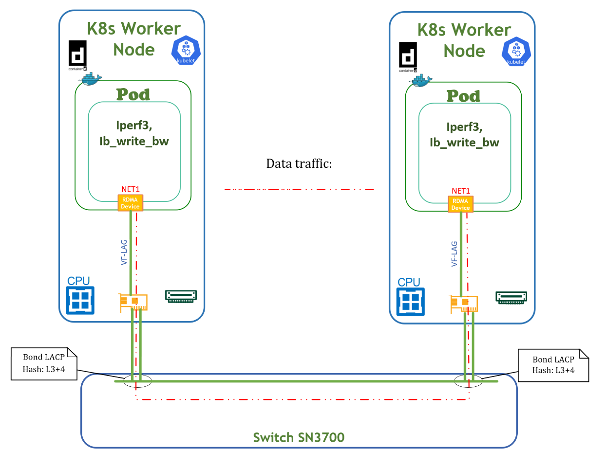
RoCE and TCP traffic testing
Traffic is shown in the Testbed Flow Diagram below. Traffic is pushed from one POD via network interface net1 to another POD via network interface net1. Traffic is distributed between both physical ports of the network adapter. The RoCE traffic test was performed using the ib_write_bw command from the Ubuntu PERFTEST inbox package and is shown below. The TCP traffic test is similar to the RoCE based test and can be performed using the iperf3 command.
Below is an example of a deployment for running benchmark tests.
apiVersion: apps/v1
kind: Deployment
metadata:
  name: test-inbox-dep
  labels:
    app: sriov
spec:
  replicas: 2
  selector:
    matchLabels:
      app: sriov
  template:
    metadata:
      labels:
        app: sriov
      annotations:
        k8s.v1.cni.cncf.io/networks: net-vst
    spec:
      containers:
      - image: < container image name >
        name: test-pod
        securityContext:
          capabilities:
            add: [ "IPC_LOCK" ]
        resources:
          requests:
            cpu: 10
            memory: 64Gi
            nvidia.com/vflag: 1
          limits:
            cpu: 10
            memory: 64Gi
            nvidia.com/vflag: 1
        command:
        - sh
        - -c
        - sleep inf
IB_WRITE_BW test server command:
ib_write_bw -d rocep57s0f0v1 -q 20 -F a
IB_WRITE_BW test client command:
ib_write_bw -d rocep57s0f0v0 192.168.101.4 --report_gbits -q 20 -F -a
Output example:
...
---------------------------------------------------------------------------------------
 #bytes     #iterations    BW peak[Gb/sec]    BW average[Gb/sec]   MsgRate[Mpps]
 2          100000           0.067015            0.066925            4.182788
 4          100000           0.14               0.14   		   4.248459
 8          100000           0.27               0.27   		   4.248299
 16         100000           0.54               0.54   		   4.246437
 32         100000           1.09               1.09   		   4.247007
 64         100000           2.18               2.17   		   4.247745
 128        100000           4.35               4.35   		   4.247277
 256        100000           8.69               8.68   		   4.239377
 512        100000           17.36              17.35  		   4.236006
 1024       100000           34.54              34.52  		   4.213616
 2048       100000           68.45              68.37  		   4.173146
 4096       100000           135.30             129.47 		   3.951161
 8192       100000           169.81             169.68 		   2.589131
 16384      100000           170.64             170.58 		   1.301397
 32768      100000           170.29             169.29 		   0.645800
 65536      100000           169.69             169.03 		   0.322402
 131072     100000           169.28             167.92 		   0.160142
 262144     100000           169.12             167.85 		   0.080038
 524288     100000           169.19             167.79 		   0.040004
 1048576    100000           168.54             168.19 		   0.020050
 2097152    100000           168.30             167.79 		   0.010001
 4194304    100000           168.34             167.97 		   0.005006
 8388608    100000           168.34             168.20 		   0.002506
---------------------------------------------------------------------------------------
The POD VF-LAG Accelerated network port received ~170Gb/s traffic according to the test.
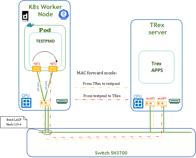
DPDK traffic emulation
DPDK traffic emulation is shown in the Testbed Flow Diagram below.
Traffic is pushed from Trex Server via ens2f0 interface to TestPMD POD via network interface net1. TestPMD POD forwards mac-address and re-routes ingress traffic via the same net2 to ens3f0 interface on Trex Server. For testing, we use 64B messages. Traffic is distributed between both physical ports of the network adapter.
TRex Server Deployment
We use TRex package v3.02 in our setup.
For a detailed TRex installation and configuration guide, see TRex Documentation.
TRex Installation and configuration steps are performed with the root user account.
1. Prerequisites.
For TRex Server, a standard server with an installed RDMA subsystem is used.
Activate the network interfaces that are used by the TRex application with netplan.
In our deployment, interfaces ens2f0 and ens2f1 are used:
# This is the network config written by 'subiquity'
network:
  ethernets:
    ens4f0:
      dhcp4: true
      dhcp-identifier: mac
    ens2f0: {}
    ens2f1: {}
  version: 2
Then re-apply netplan and check link status for ens2f0/ens2f1 network interfaces.
# netplan apply
# rdma link
link mlx5_0/1 state ACTIVE physical_state LINK_UP netdev ens2f0
link mlx5_1/1 state ACTIVE physical_state LINK_UP netdev ens2f1
link mlx5_2/1 state ACTIVE physical_state LINK_UP netdev ens4f0
link mlx5_3/1 state DOWN physical_state DISABLED netdev ens4f1
Update MTU sizes for interfaces ens2f0 and ens2f1.
# ip link set ens2f0 mtu 9000
# ip link set ens2f1 mtu 9000
2. Installation.
Create a TRex work directory and extract the TRex package.
# cd /tmp
# wget https://trex-tgn.cisco.com/trex/release/v3.02.tar.gz --no-check-certificate
# mkdir /scratch
# cd /scratch
# tar -zxf /tmp/v3.02.tar.gz
# chmod 777 -R /scratch
3. First-Time Scripts.
The next step continues from folder /scratch/v3.02.
Run the TRex configuration script in interactive mode. Follow the instructions on the screen to create a basic config file /etc/trex_cfg.yaml.
# ./dpdk_setup_ports.py -i
The /etc/trex_cfg.yaml configuration file is created. This file will be changed later to suit our setup.
Performance Testing
A performance test is shown next for DPDK traffic emulation between the TRex traffic generator and a TESTPMD application running on a K8s Worker node, in accordance with the Testbed diagram presented above.
Prerequisites
Before starting the test, update the TRex configuration file /etc/trex_cfg.yaml with a mac-address of the high-performance interface from the TESTPMD pod. Below are the steps to complete this update.
-
Run pod on the K8s cluster with TESTPMD apps according to the YAML configuration file testpmd-inbox.yaml (container image should include InfiniBand userspace drivers and TESTPMD apps).
apiVersion: apps/v1
kind: Deployment
metadata:
  name: dpdk-inbox-dep
  labels:
    app: sriov
spec:
  replicas: 2
  selector:
    matchLabels:
      app: sriov
  template:
    metadata:
      labels:
        app: sriov
      annotations:
        k8s.v1.cni.cncf.io/networks: net-vst,net-vst
    spec:
      containers:
      - image: < container image name >
        name: dpdk-pod
        securityContext:
          capabilities:
            add: [ "IPC_LOCK", "NET_ADMIN" ]
        volumeMounts:
        - mountPath: /hugepages
          name: hugepage
        resources:
          requests:
            cpu: 10
            memory: 64Gi
            nvidia.com/vflag: 2
            hugepages-1Gi: 16Gi
          limits:
            cpu: 10
            memory: 64Gi
            nvidia.com/vflag: 2
            hugepages-1Gi: 16Gi
        command:
        - sh
        - -c
        - sleep inf
      volumes:
      - name: hugepage
        emptyDir:
          medium: HugePages
Deploy using the following command:
# kubectl apply -f testpmd-inbox.yaml -
Get the network information from the deployed pod by running the following commands:
# kubectl get pod -o wide NAME READY STATUS RESTARTS AGE IP NODE NOMINATED NODE READINESS GATES dpdk-inbox-dep-676476c78d-glbfs 1/1 Running 0 30s 10.233.92.5 node3 <none> <none> # kubectl exec -it dpdk-inbox-dep-676476c78d-glbfs -- ip a s 1: lo: <LOOPBACK,UP,LOWER_UP> mtu 65536 qdisc noqueue state UNKNOWN group default qlen 1000 link/loopback 00:00:00:00:00:00 brd 00:00:00:00:00:00 inet 127.0.0.1/8 scope host lo valid_lft forever preferred_lft forever inet6 ::1/128 scope host valid_lft forever preferred_lft forever 3: eth0@if72: <BROADCAST,MULTICAST,UP,LOWER_UP> mtu 1450 qdisc noqueue state UP group default link/ether d2:c5:68:a5:47:36 brd ff:ff:ff:ff:ff:ff link-netnsid 0 inet 10.233.65.239/24 brd 10.233.65.255 scope global eth0 valid_lft forever preferred_lft forever inet6 fe80::d0c5:68ff:fea5:4736/64 scope link valid_lft forever preferred_lft forever 50: net1: <BROADCAST,MULTICAST,UP,LOWER_UP> mtu 9000 qdisc mq state UP group default qlen 1000 link/ether be:24:2d:ea:9a:73 brd ff:ff:ff:ff:ff:ff inet 192.168.101.3/24 brd 192.168.101.255 scope global net1 valid_lft forever preferred_lft forever inet6 fe80::bc24:2dff:feea:9a73/64 scope link valid_lft forever preferred_lft forever 57: net2: <BROADCAST,MULTICAST,UP,LOWER_UP> mtu 9000 qdisc mq state UP group default qlen 1000 link/ether 76:c8:42:33:bf:94 brd ff:ff:ff:ff:ff:ff inet 192.168.101.5/24 brd 192.168.101.255 scope global net2 valid_lft forever preferred_lft forever inet6 fe80::74c8:42ff:fe33:bf94/64 scope link valid_lft forever preferred_lft forever -
Update the TRex configuration file /etc/trex_cfg.yaml with mac-address of the NET1 and NET2 network interfaces.
### Config file generated by dpdk_setup_ports.py ### - version: 2 interfaces: ['81:00.0', '81:00.1'] port_info: - dest_mac: be:24:2d:ea:9a:73 # MAC OF NET1 INTERFACE src_mac: 0c:42:a1:1d:d1:7a - dest_mac: 76:c8:42:33:bf:94 # MAC OF NET2 INTERFACE src_mac: 0c:42:a1:1d:d1:7b platform: master_thread_id: 0 latency_thread_id: 12 dual_if: - socket: 0 threads: [2,3,4,5,6,7,8,9,10,11,12,13,14,15,16,17,18,19,20,21,22,23] -
Run TESTPMD apps in container:
# kubectl exec -it test-deployment-676476c78d-glbfs -- bash
root@test-deployment-676476c78d-glbfs:/tmp# # cat /sys/fs/cgroup/cpuset.cpus
12-21
# export | grep VFLAG
declare -x PCIDEVICE_NVIDIA_COM_VFLAG="0000:39:01.1,0000:39:00.2"
# dpdk-testpmd  -l 12-21 -m 1024 -a 0000:39:01.1 -a 0000:39:00.2 -- --burst=64 --txd=1024 --rxd=1024 --mbcache=512 --rxq=4 --txq=4 --nb-cores=1 --rss-udp --forward-mode=mac --eth-peer=0,0c:42:a1:1d:d1:63 --eth-peer=1,0c:42:a1:1d:d1:7b -a -i ...
testpmd>
Specific TESTPMD parameters:
$PCIDEVICE_NVIDIA_COM_VFLAG - system variable PCI addresses of NET1, NET2
More information about additional TESTPMD parameters:
https://doc.dpdk.org/guides/testpmd_app_ug/run_app.html?highlight=testpmd
https://doc.dpdk.org/guides/linux_gsg/linux_eal_parameters.html -
Run the TRex traffic generator on the TRex server:
# cd /scratch/v3.02/
# ./t-rex-64 -i -c 14 --no-ofed-check
Open a second screen on TRex server and create the traffic generation file mlnx-trex.py in folder /scratch/v3.02:
from trex_stl_lib.api import *

class STLS1(object):

    def create_stream (self):

        pkt = Ether()/IP(src="16.0.0.1",dst="48.0.0.1")/UDP(dport=12)/(22*'x')

        vm = STLScVmRaw( [
                                STLVmFlowVar(name="v_port",
                                                min_value=4337,
                                                  max_value=5337,
                                                  size=2, op="inc"),
                                STLVmWrFlowVar(fv_name="v_port",
                                            pkt_offset= "UDP.sport" ),
                                STLVmFixChecksumHw(l3_offset="IP",l4_offset="UDP",l4_type=CTRexVmInsFixHwCs.L4_TYPE_UDP),

                            ]
                        )

        return STLStream(packet = STLPktBuilder(pkt = pkt ,vm = vm ) ,
                                mode = STLTXCont(pps = 8000000) )


    def get_streams (self, direction = 0, **kwargs):
        # create 1 stream
        return [ self.create_stream() ]


# dynamic load - used for trex console or simulator
def register():
    return STLS1()
Next, run the TRex console and generate traffic to TESTPMD pod,# cd /scratch/v3.02/ # ./trex-console Using 'python3' as Python interpeter Connecting to RPC server on localhost:4501 [SUCCESS] Connecting to publisher server on localhost:4500 [SUCCESS] Acquiring ports [0, 1]: [SUCCESS] Server Info: Server version: v3.02 @ STL Server mode: Stateless Server CPU: 11 x Intel(R) Xeon(R) CPU E5-2650 v4 @ 2.20GHz Ports count: 2 x 100Gbps @ MT2892 Family [ConnectX-6 Dx] -=TRex Console v3.0=- Type 'help' or '?' for supported actions trex> tui<enter> ... tui> start -f mlnx-trex.py -m 30mpps -p 0 ... Global Statistitcs connection : localhost, Port 4501 total_tx_L2 : 23.9 Gbps version : STL @ v3.02 total_tx_L1 : 20.93 Gbps cpu_util. : 82.88% @ 11 cores (11 per dual port) total_rx : 17.31 Gbps rx_cpu_util. : 0.0% / 0 pps total_pps : 29.51 Mpps async_util. : 0.05% / 11.22 Kbps drop_rate : 0 bps total_cps. : 0 cps queue_full : 0 pkts ...Summary
From the above test, it is evident that the desired traffic is ~30mpps with a VF-LAG network port in POD.
TRex and TESTPMD are powerful tools for network performance testing, but they need some fine-tuning to achieve optimal results.
The performance results listed in this guide are indicative and should not be considered as formal performance targets for NVIDIA products.
Done!
Authors
|
|
Vitaliy Razinkov Vitaliy Razinkov is a Solutions Architect on the NVIDIA Networking team, specializing in complex Kubernetes, OpenShift, and Microsoft solutions. With over 25 years of experience in senior technical roles, he brings deep expertise in designing and implementing advanced infrastructures. Vitaliy has authored several reference design guides on Microsoft technologies, RoCE/RDMA-accelerated machine learning in Kubernetes/OpenShift, and containerized solutions—all available on the NVIDIA Networking Documentation site. |

|
|
Amir Zeidner For several years, Amir has worked as a Solutions Architect primarily in the Telco space, leading advanced solutions to answer 5G, NFV, and SDN networking infrastructure requirements. Amir’s expertise in data plane acceleration technologies, such as Accelerated Switching and Network Processing (ASAP²) and DPDK, together with a deep knowledge of open-source cloud-based infrastructures, allows him to promote and deliver unique end-to-end NVIDIA Networking solutions throughout the Telco world. |

|
|
Itai Levy
Over the past few years, Itai Levy has worked as a Solutions Architect and member of the NVIDIA Networking “Solutions Labs” team. Itai designs and executes cutting-edge solutions around Cloud Computing, Software-Defined Networking, Storage and Security. His main areas of expertise include NVIDIA BlueField Data Processing Unit (DPU) solutions and accelerated K8s/OpenStack platforms. |

Last updated: