Virtualization supported capabilities:
Hyper-V with VMQ
|
System Requirements |
|
|---|---|
|
Operating Systems: |
Windows Server 2012 and above |
Using Hyper-V with VMQ
NVIDIA® WinOF-2 driver includes a Virtual Machine Queue (VMQ) interface to support Microsoft Hyper-V network performance improvements and security enhancement.
VMQ interface supports:
-
Classification of received packets by using the destination MAC address to route the packets to different receive queues
-
NIC ability to use DMA to transfer packets directly to a Hyper-V child-partition shared memory
-
Scaling to multiple processors, by processing packets for different virtual machines on different processors.
![]()
-
Open Hyper-V Manager.
-
Right-click the desired Virtual Machine (VM), and left-click Settings in the pop-up menu.
-
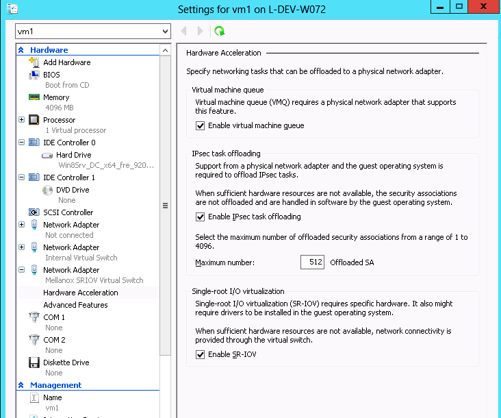
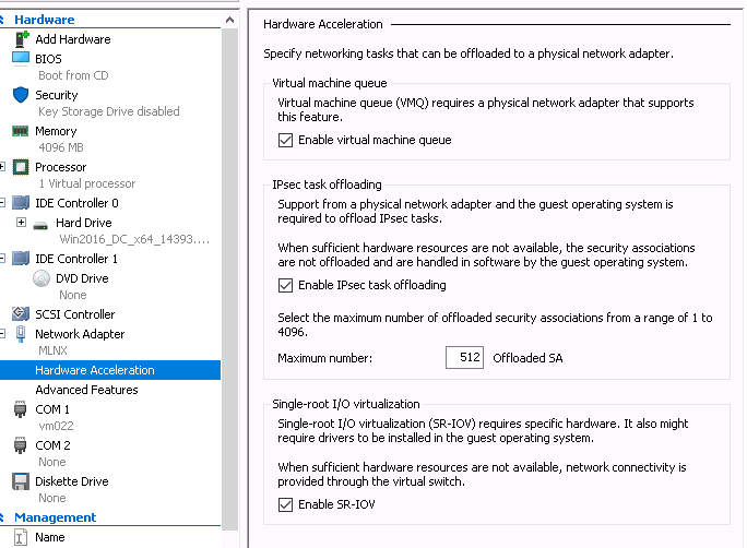
In the Settings window, under the relevant network adapter, select “Hardware Acceleration”.
-
Check/uncheck the box “Enable virtual machine queue” to enable/disable VMQ on that specific network adapter.
![]()
-
Enable VMQ on a specific VM: Set-VMNetworkAdapter <VM Name> -VmqWeight 100
-
Disable VMQ on a specific VM: Set-VMNetworkAdapter <VM Name> -VmqWeight 0
Network Virtualization using Generic Routing Encapsulation (NVGRE)
VF CPU MonitorNetwork Virtualization using Generic Routing Encapsulation (NVGRE) offload is currently supported in Windows Server 2012 R2 with the latest updates for Microsoft.
For further information, please refer to the Microsoft’s “Network Virtualization using Generic Routing Encapsulation (NVGRE) Task Offload” document.
Enabling/Disabling NVGRE Offloading
To leverage NVGRE to virtualize heavy network IO workloads, the NVIDIA® ConnectX®-4 network NIC provides hardware support for GRE offload within the network NICs by default.
![]()
-
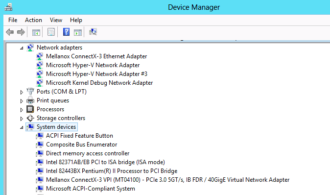
Open the Device Manager.
-
Go to the Network adapters.
-
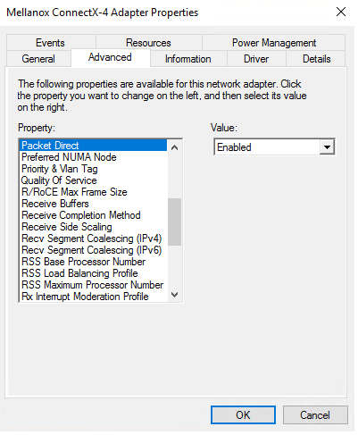
Right click ‘Properties’ on Mellanox ConnectX®-4 Ethernet Adapter card.
-
Go to Advanced tab.
-
Choose the ‘Encapsulate Task Offload’ option.
-
Set one of the following values:
-
Enable - GRE offloading is Enabled by default
-
Disabled - When disabled the Hyper-V host will still be able to transfer NVGRE traffic, but TCP and inner IP checksums will be calculated by software that significantly reduces performance.
-
If both the NVGRE and VXLAN are disabled, the driver configures the inner rule to be ready in case encapsulation will be enabled (e.g., OID_RECEIVE_FILTER_SET_FILTER with flag NDIS_RECEIVE_FILTER_PACKET_ENCAPSULATION is received). That means while working without non-tunneled rule, no traffic will match this filter until encapsulation is enabled.
When using NVGRE and VXLAN when in NIC mode in NVIDIA BlueField-2 DPU, please note known issues 3040551 in the Release Notes.
Configuring NVGRE using PowerShell
Hyper-V Network Virtualization policies can be centrally configured using PowerShell 3.0 and PowerShell Remoting.
For further information of now to configure NVGRE using PowerShell, please refer to Microsoft’s “Step-by-Step: Hyper-V Network Virtualization” blog.
Once the configuration using PowerShell is completed, verifying that packets are indeed encapsulated as configured is possible through any packet capturing utility. If configured correctly, an encapsulated packet should appear as a packet consisting of the following headers:
-
Outer ETH Header
-
Outer IP
-
GRE Header
-
Inner ETH Header
-
Original Ethernet Payload
Single Root I/O Virtualization (SR-IOV)
Single Root I/O Virtualization (SR-IOV) is a technology that allows a physical PCIe device to present itself multiple times through the PCIe bus. This technology enables multiple virtual instances of the device with separate resources. NVIDIA® adapters are capable of exposing up to 127 virtual instances called Virtual Functions (VFs) per port. These virtual functions can then be provisioned separately. Each VF can be seen as an addition device connected to the Physical Function. It also shares resources with the Physical Function.
SR-IOV is commonly used in conjunction with an SR-IOV enabled hypervisor to provide virtual machines direct hardware access to network resources hence increasing its performance.
This guide demonstrates the setup and configuration of SR-IOV, using NVIDIA® adapter cards family. SR-IOV VF is a single port device.
SR-IOV over Hyper-V
|
System Requirements |
|
|---|---|
|
Server and BIOS |
A server and BIOS with SR-IOV support. Note: BIOS settings may require an update to enable virtualization support and SR-IOV support. |
|
Hypervisor OS: |
|
|
Virtual Machine (VM) OS: |
Windows Server 2012 and above |
|
Adapter cards |
NVIDIA® ConnectX®-4 onward adapter cards |
|
SR-IOV supported driver version: |
|
Feature Limitations
-
SR-IOV in IPoIB node:
-
LID based IPoIB is supported with the following limitations:
-
It does not support routers in the fabric
-
It supports up to 2^15-1 LIDs
-
-
-
No synthetic path: The SR-IOV path that goes thru the WinOF-2 driver
Although both the NVIDIA® adapter - Virtual Function (VF) and the NetVSC will be presented in the VM, it is recommended to use only the NVIDIA® interface.
Configuring SR-IOV Host Machines
The sections below describe the required flows for configuring the host machines:
Enabling SR-IOV in BIOS
Depending on your system, perform the steps below to set up your BIOS. The figures used in this section are for illustration purposes only.
For further information, please refer to the appropriate BIOS User Manual.
It is recommended to enable the "above 4G decoding" BIOS setting for features that require a large amount of PCIe resources (e.g., SR-IOV with numerous VFs, PCIe Emulated Switch, Large BAR Requests).
![]()
-
Make sure the machine’s BIOS supports SR-IOV.
Please, consult BIOS vendor website for SR-IOV supported BIOS versions list. Update the BIOS version if necessary. -
Enable SR-IOV according to the BIOS vendor guidelines.
For example:-
Enable SR-IOV.
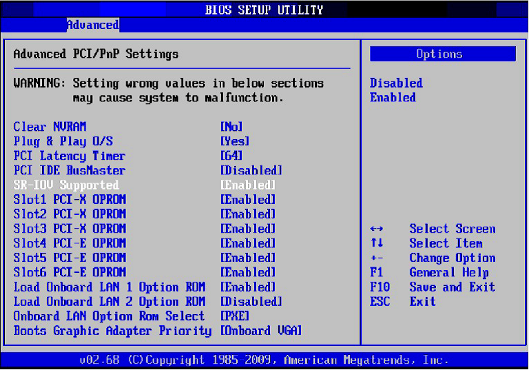
-
Enable “Intel Virtualization Technology” Support.
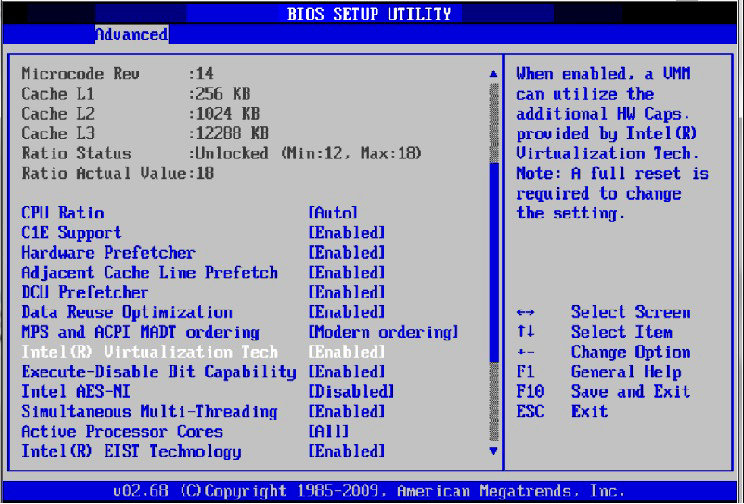
For further details, please refer to the vendor's website.
-
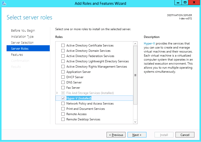
Installing Hypervisor Operating System
![]()
-
Install Windows Server 2012 R2
-
Install Hyper-V role:
-
Go to: Server Manager -> Manage -> Add Roles and Features and set the following:
-
Installation Type -> Role-based or Feature-based Installation
-
Server Selection -> Select a server from the server pool
-
Server Roles -> Hyper-V (see figures below)
-
-
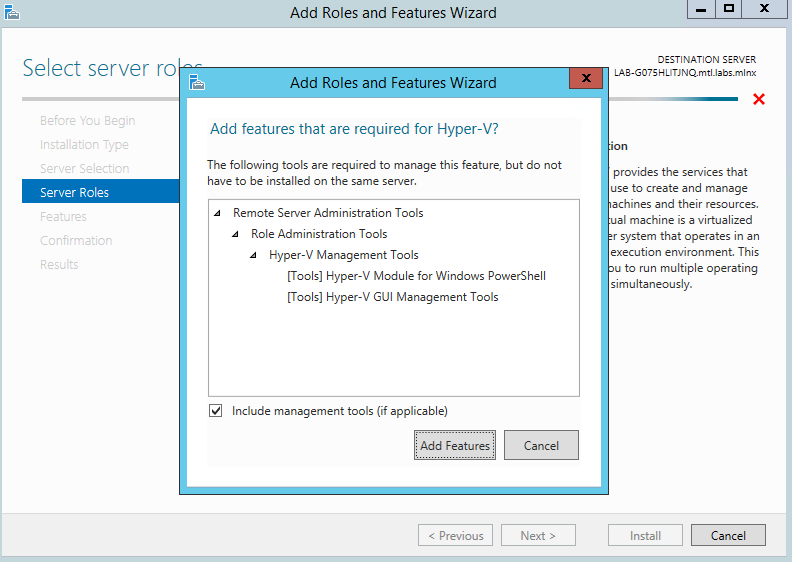
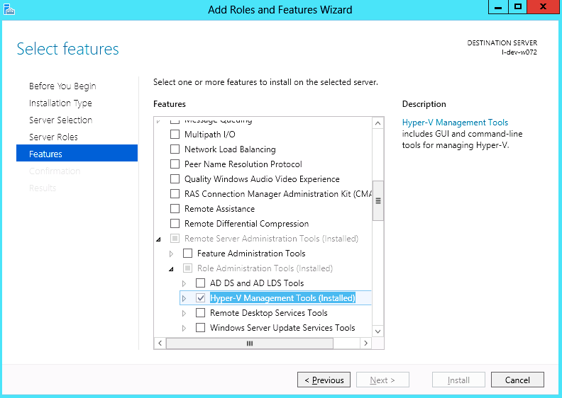
Install Hyper-V Management Tools.
Features - > Remote Server Administration Tools -> Role Administration Tools ->Hyper-V Administration Tool.
-
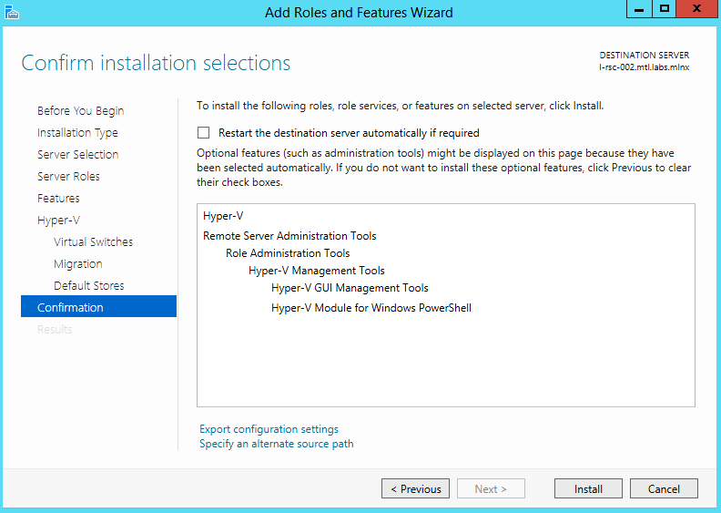
Confirm installation selection.

-
Click Install.
-
Reboot the system.
Verifying SR-IOV Support within the Host Operating System
![]()
-
Go to: Start-> Windows Powershell.
-
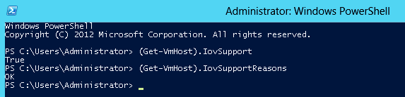
Run the following PowerShell commands.
PS $ (Get-VmHost).IovSupport
PS $ (Get-VmHost).IovSupportReasons
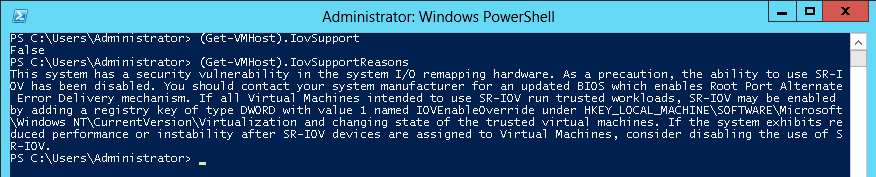
In case that SR-IOV is supported by the OS, the output in the PowerShell is as in the figure below.
If the BIOS was updated according to BIOS vendor instructions and you see the message displayed in the figure below, update the registry configuration as described in the (Get-VmHost).IovSupportReasons message.
-
Reboot
-
Verify the system is configured correctly for SR-IOV as described in Steps 1/2.
Verifying Sufficient Resources are Available in the Adapter to Enable SR-IOV VFs
![]()
-
Go to: Start-> Windows Powershell.
-
Run the following PowerShell commands.
PS C:\Windows\system32> Get-NetAdapterSriovExample:
Name : SLOT 4 Port 1
InterfaceDescription : Mellanox ConnectX-4 Adapter
Enabled : True
SriovSupport : NoVfBarSpace
SwitchName : “Default Switch”
NumVFs : 32
If the “SriovSupport” field value shows “NoVfBarSpace” , SR-IOV cannot be used on this network adapter as there are not enough PCI Express BAR resources available.
To use SR-IOV, you need to reduce the number of VFs to the number supported by the OS.
For further information, see https://technet.microsoft.com/en-us/library/jj130915(v=wps.630).aspx
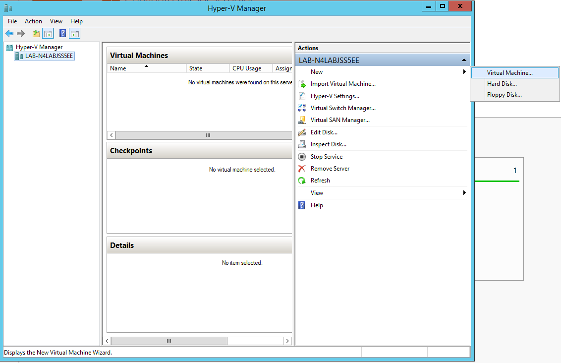
Creating a Virtual Machine
![]()
-
Go to: Server Manager -> Tools -> Hyper-V Manager.
-
Go to: New->Virtual Machine and set the following:
-
Name: <name>
-
Startup memory: 4096 MB
-
Connection: Not Connected
-
-
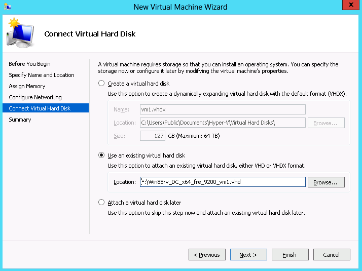
Connect the virtual hard disk in the New Virtual Machine Wizard.
-
Go to: Connect Virtual Hard Disk -> Use an existing virtual hard disk.
-
Select the location of the VHD file.
Configuring Host Memory Limit per VF
In SR-IOV mode, the host allocates memory resources per the adapter`s needs for each VF. It is important to limit the amount of memory that the VF can receive from the host, in order to ensure the host’s stability. To prevent excessive allocation, the MaxFWPagesUsagePerVF registry key must be configured to the maximum number of 4KB pages that the host could allocate for VFs resources. In case of attempting to use more pages then configured, an error will be printed to the system event log. For more information, see See SR-IOV Options.
Configuring NVIDIA® Network Adapter for SR-IOV
The sections below describe the required flows for configuring the NVIDIA® Network Adapter for SR-IOV:
Enabling SR-IOV in Firmware
For non-NVIDIA® (OEM) branded cards you may need to download and install the new firmware.
![]()
mlxconfig is part of MFT tools used to simplify firmware configuration. The tool is available using MFT v3.6.0 or higher.
-
Download MFT for Windows.
-
Get the device ID (look for the “_pciconf” string in the output).
mst status
Example:MST devices: ------------ mt4115_pciconf0
-
Check the current SR-IOV configuration.
mlxconfig -d mt4115_pciconf0 q
Example:Device #1: ---------- Device type: ConnectX4 PCI device: mt4115_pciconf0 Configurations: Current SRIOV_EN N/A NUM_OF_VFS N/A WOL_MAGIC_EN_P2 N/A LINK_TYPE_P1 N/A LINK_TYPE_P2 N/A
-
Enable SR-IOV with 16 VFs.
mlxconfig -d mt4115_pciconf0 s SRIOV_EN=1 NUM_OF_VFS=16
All servers are guaranteed to support 16 VFs. Increasing the number of VFs can lead to exceeding the BIOS limit of MMIO available address space.
OS limits the maximum number of VFs to 32 per Network Adapter.
To increase the number of VFs, the following PowerShell command should be used: Set-NetAdapterSRIOV - name <AdapterName> -NumVFs <Required number of VFs>
Example:
Device #1:
----------

Device type: ConnectX4
PCI device: mt4115_pciconf0

Configurations: Current New
SRIOV_EN N/A 1
NUM_OF_VFS N/A 16
WOL_MAGIC_EN_P2 N/A N/A
LINK_TYPE_P1 N/A N/A
LINK_TYPE_P2 N/A N/A

Apply new Configuration? ? (y/n) [n] : y
Applying... Done!
-I- Please reboot machine to load new configurations.
Configuring IPoIB in SR-IOV
Subnet Manager (SM) Configuration
The SM should be up in the fabric in order to work with IPoIB, and can be run on a switch or on a Linux host.
-
Switch SM Configuration
-
Install the SM image that supports virtualization (3.6.4640 version and above). For more details, please refer to the switch operating system User Manual.
-
Enter the config mode.
switch > enable
switch # config terminal
-
Enable the SM (to disable the SM, type: no ib sm).
ib sm
-
Enable virtualization.
ib sm virt enable
-
Save the configuration.
configuration write
-
Restart the switch.
reload
-
Validate the Subnet Manager is enabled.
show ib sm
-
Validate Virtualization is enabled.
show ib sm virt
For more details, please refer to the Subnet Manager (SM) section in the MLNX-OS® User Manual for VPI.
-
Linux Host SM Configuration
-
Enable the virtualization by setting the virt_enable field to 2 on the /etc/opensm/opensm.conf file.
-
Start OpenSM and bind it to a specific port.
opensm -e -B -g <Port GUID>
OpenSM may be bound to one port at a time. If the given GUID is 0, the OpenSM displays a list of possible port GUIDs and awaits user input. Without “-g”, the OpenSM attempts to use the default port.
Firmware Configuration
-
Get the device name.
mst status
-
Show device configurations.
mlxconfig -d <device name> q
-
Enable SR-IOV: (1 = Enable).
mlxconfig -d <device name> set SRIOV_EN=1
-
Set max VFs count.
mlxconfig -d <device name> set NUM_OF_VFS=<Count>
-
Configure device to work in IB mode (1=IB).
mlxconfig -d <device name> set LINK_TYPE_P1=1 set LINK_TYPE_P2=1
-
Enable LID based IPoIB.
mlxconfig -d <Device name> set SRIOV_IB_ROUTING_MODE_P1=1
mlxconfig -d <Device name> set SRIOV_IB_ROUTING_MODE_P2=1
-
Restart the firmware.
mlxfwreset -d <Device name> r --yes
The mlxconfig and mlxfwreset tools are a part of the WinMFT package. For more details, please refer to the MFT User Manual.
To enable IPoIB LID base by mlxconfig, install MFT v4.8.0-25, and above.
Configuring Virtual Machine Networking (InfiniBand SR-IOV Only)
For further details on enabling/configuring SR-IOV on KVM, please refer to section “Single Root IO Virtualization (SR-IOV)” in MLNX_OFED for Linux User Manual.
Configuring Virtual Machine Networking
![]()
-
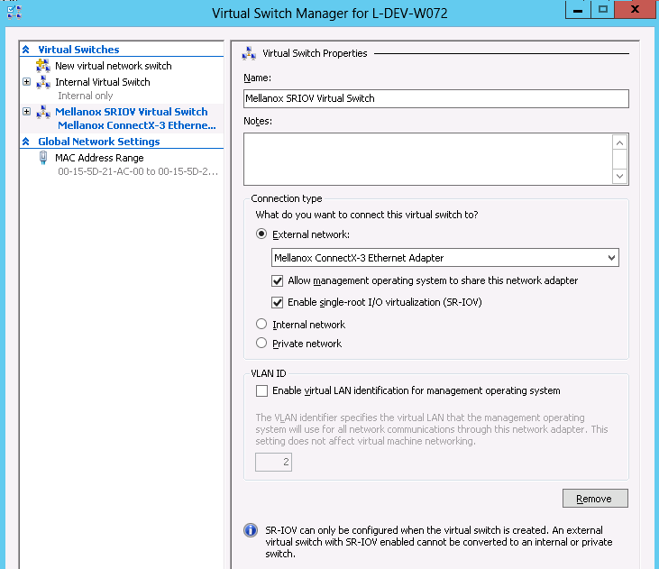
Create an SR-IOV-enabled Virtual Switch over NVIDIA® Ethernet Adapter.
- Go to: Start -> Server Manager -> Tools -> Hyper-V Manager
- Hyper-V Manager: Actions -> Virtual SwitchManager -> External-> Create Virtual Switch -
Set the following:
- Name:
- External network:
- Enable single-root I/O virtualization (SR-IOV)
-
Click Apply.
-
Click OK.
-
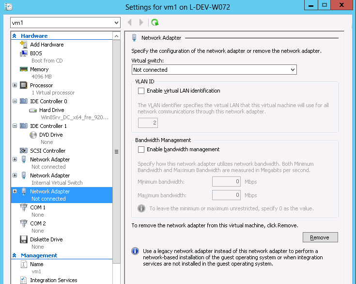
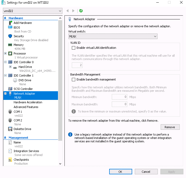
Add a VMNIC connected to a NVIDIA® vSwitch in the VM hardware settings:
- Under Actions, go to Settings -> Add New Hardware-> Network Adapter-> OK
- In “Virtual Switch” dropdown box, choose Mellanox SR-IOV Virtual Switch
-
Enable the SR-IOV for Mellanox VMNIC:
-
Open VM settings Wizard.
-
Open the Network Adapter and choose Hardware Acceleration.
-
Tick the “Enable SR-IOV” option.
-
Click OK.
-
-
Start and connect to the Virtual Machine:
-
Select the newly created Virtual Machine and go to: Actions panel-> Connect.
In the virtual machine window go to: Actions-> Start -
Copy the WinOF driver package to the VM using Mellanox VMNIC IP address.
-
Install WinOF driver package on the VM.
-
Reboot the VM at the end of installation.
-
Verify that Mellanox Virtual Function appears in the device manager.
To achieve best performance on SR-IOV VF, please run the following powershell commands on the host:
-
For 10Gbe:
PS $ Set-VMNetworkAdapter -Name "Network Adapter" -VMName vm1 -IovQueuePairsRequested 4 -
For 40Gbe and 56Gbe:
PS $ Set-VMNetworkAdapter -Name "Network Adapter" -VMName vm1 -IovQueuePairsRequested 8
VF Spoof Protection
WinOF-2 supports two levels of spoof protection:
-
Hypervisor sets VF's MAC address and only packets with that MAC can be transmitted by the VF
-
Hypervisor can control allowed Ethertypes that the VF can transmit
If a VF attempts to transmit packets with undesired source MAC or Ethertype, the packets will be dropped by an internal e-Switch.
By default, the anti-spoof filter is enabled with the following Ethertypes:
-
Internet Protocol version 4 (IPv4) (0x0800)
-
Internet Protocol Version 6 (IPv6) (0x86DD)
-
Address Resolution Protocol (ARP) (0x0806)
The hypervisor can configure an Ethertype table for VFs, which includes a set of allowed Ethertypes values for transmission via the NIC registry. The registry keys are as follows:
|
Key Name |
Key Type |
Values |
Description |
|---|---|---|---|
|
VFAllowedTxEtherTypeListEnab le |
REG_SZ |
0 = Disabled 1 = Enabled (default) |
Enables/disables the feature |
|
VFAllowedTxEtherType0 |
REG_DWORD |
Ethertype value |
The first Ethertype to allow VF to transmit |
|
VFAllowedTxEtherType1 |
REG_DWORD |
Ethertype value |
The second Ethertype to allow VF to transmit |
|
VFAllowedTxEtherType2 |
REG_DWORD |
Ethertype value |
The third Ethertype to allow VF to transmit |
|
VFAllowedTxEtherType3 |
REG_DWORD |
Ethertype value |
The fourth Ethertype to allow VF to transmit |
|
VFAllowedTxEtherType4 |
REG_DWORD |
Ethertype value |
The fifth Ethertype to allow VF to transmit |
|
VFAllowedTxEtherType5 |
REG_DWORD |
Ethertype value |
The sixth Ethertype to allow VF to transmit |
|
VFAllowedTxEtherType6 |
REG_DWORD |
Ethertype value |
The seventh Ethertype to allow VF to transmit |
|
VFAllowedTxEtherType7 |
REG_DWORD |
Ethertype value |
The eighth Ethertype to allow VF to transmit |
-
By default, the feature is enabled and uses the default Ethertype table.
-
The Source MAC protection cannot be disabled, and the Ethertype protection can be disabled by setting the VFAllowedTxEtherTypeListEnable key to 0.
-
When the feature is disabled, only the Ethernet flow control protocol (0x8808) is restricted to be transmitted by the VF.
-
Configuring at least one Ethertype in the registry will override the default table of the Ethertypes mentioned above.
VF’s DHCP Redirections
This feature forces every received\sent DHCP packet to be redirected to PF, including DHCP packets sent or received for VFs. The detection of a packet as a DHCP is done by checking UDP-Ports 67 and 68.
When using devices older than ConnectX-5 (i.e. ConnectX-4 and ConnectX-4 Lx) and when this capability is set to ‘on’, the VF’s version must be higher than WinOF-2 v2.50.
To enable this new capability, the steps below are required:
-
Set the PF to work on promiscuous mode to enable PF to receive DHCP packet from various ethernet addresses.
-
Add to the NIC a new registry named “RedirectVfDHCPToPF” and set this registry to ‘1’.
|
Key Name |
Key Type |
Values |
Description |
|---|---|---|---|
|
RedirectVfDHCPToPF |
REG_SZ |
0 = Disabled (default) 1 = Enabled |
Enables/disables the feature. Note: After changing the registry key'’s value, driver restart is required. |
VF Monitoring
The feature is not supported in VMs, only in Hyper-V Host.
VF CPU Monitor capability allows the user to check two characteristics of VFs, namely – VF ‘FwCpuUsage’ and ‘Errors2FW’ counters. If the values of these counters are too high, warnings will be presented in the Event Log. The warnings come from the Host driver, which reads the ‘FwCpuUsage’ and ‘Errors2FW’ counters automatically once in VfCpuMonBatchPeriodSec seconds, compares the results with the previous reading, and issues warnings if the difference in values is greater than VfCpuMonFwCpuUsageMax and VfCpuMonErrors2FwMax thresholds correspondently.
The Event message format is as follows:
VF <vf_id> used too many resources over the last %4 seconds: FwCpuUsage %5%, Errors2Fw %6.
Note that <vf_id> can theoretically be incorrect if the reported VF was de-attached and another new VF was assigned its number.
For further information on detach/attach events see Microsoft Event Log file %SystemRoot%\System32\Winevt\Logs\Microsoft-Windows-Hyper-V-Worker-Admin.evtx.
Customer Facilities
-
Batch Request: The driver reads the VF
‘FwCpuUsage’and‘Errors2FW’counters using new FW “batch request” which allows reading one counter from all VFs in a single command. The result of this command is a resource dump. The user can perform the batch request, using mlx5cmd.exe (see more inResource Dump
section).
The below are examples of how to read the counters:-
To read the VF
‘FwCpuUsage’counter from VF0 to VF31:mlx5cmd.exe -dbg -ResourceDump -Dump -Segment 0x5000 -Index1 1 -NumOfObj1 32 -Index2 1 –Depth 1
-
To read the VF
‘Errors2FW’counter from VF1 to VF8:mlx5cmd.exe -dbg -ResourceDump -Dump -Segment 0x5000 -Index1 2 -NumOfObj1 8 -Index2 2 –Depth 1
-
The tool will print the name of the folder with the result, written into a file.
The ‘-NumOfObj1’ special values 0xffff and 0xfffe are not supported for the segment 0x5000.
-
Feature state" The user can check the state of the feature by running the ‘mlx5cmd -Features’ command. If the feature is not supported by the firmware or was disabled by default or by the user, the tool prints
State: Disabled
Otherwise, the tool prints
State: Enabled-
To disable/enable the feature, change the value of the
VfCpuMonEnableparameter. -
To print the configuration parameters, run:
mlx5cmd -RegKeys –DynamicKeys | grep VfCpu
-
For further information, see “VF Monitoring Registry Keys”.
Virtual Machine Multiple Queue (VMMQ)
VMMQ is supported in Windows Server 2016 and above only, when using Ethernet mode (No IPoIB).
Virtual Machine Multiple Queues (VMMQ), formerly known as Hardware vRSS, is a NIC offload technology that provides scalability for processing network traffic of a VPort in the host (root partition) of a virtualized node. In essence, VMMQ extends the native RSS feature to the VPorts that are associated with the physical function (PF) of a NIC including the default VPort.
VMMQ is available for the VPorts exposed in the host (root partition) regardless of whether the NIC is operating in SR-IOV or VMQ mode.
|
System Requirements |
|
|---|---|
|
Operating System(s): |
Windows Server 2016 |
|
Adapter Cards |
NVIDIA® ConnectX-4/ConnectX-4 Lx/ConnectX-5 adapter card family |
SR-IOV Support Limitations
The below table summarizes the SR-IOV working limitations, and the driver’s expected behavior in unsupported configurations.
|
WinOF-2 Version |
ConnectX-4 Version |
Adapter Mode |
||
|---|---|---|---|---|
|
InfiniBand |
Ethernet |
|||
|
SR-IOV On |
SR-IOV Off |
SR-IOV On/Off |
||
|
Earlier versions |
Up to 12.16.1020 |
Driver will fail to load and show "Yellow Bang" in the device manager. |
No limitations |
|
|
1.50 onwards |
12.17.2020 onwards
|
“Yellow Bang” unsupported mode - disable SR-IOV via mlxConfig |
OK |
No limitations |
For further information on how to enable/disable SR-IOV, please refer to section Single Root I/O Virtualization (SR-IOV).
Enabling/Disabling VMMQ
-
On the Driver Level

-
Go to: Display Manager-> Network adapters->Mellanox ConnectX-4/ConnectX-5 Ethernet Adapter->Properties-> advanced tab->Virtual Switch Rss
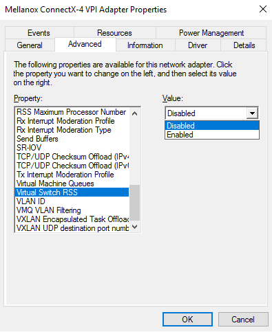
-
Select Enabled or Disabled
-
![]()
Set the RssOnHostVPorts registry key in the following path to either 1 (enabled) or 0 (disabled).
HKLM\SYSTEM\CurrentControlSet\Control\Class\{4d36e972-e325-11ce-bfc1-08002be10318}\<nn>\* RssOnHostVPorts
-
On a VPort
PS $ Set-VMNetworkAdapter -Name "Virtual Adapter Name" -VmmqEnabled $truePS $ Set-VMNetworkAdapter -Name "Virtual Adapter Name" -VmmqEnabled $false
Since the VMMQ is an offload feature for vRss, vRss must be enabled prior to enabling VMMQ.
Controlling the Number of Queues Allocated for a vPort
The requested number of queues for a virtual network adapter (vPort) can be set by invoking this PS cmdlet:
PS $ Set-VMNetworkAdapter -VMName "VM Name" -name "Virtual Adapter Name" -VmmqQueuePairs <number>
The number provided to this cmdlet is the requested number of queues per vPort. However, the OS might decide to not fulfill the request due to some resources and other factors considerations.
Network Direct Kernel Provider Interface
As of v1.45, WinOF-2 supports NDIS Network Direct Kernel Provider Interface version 2. The Network Direct Kernel Provider Interface (NDKPI) is an extension to NDIS that allows IHVs to provide kernel-mode Remote Direct Memory Access (RDMA) support in a network adapter.
|
System Requirement |
|
|---|---|
|
Operating System: |
Windows Server 2012 R2 and above (Without NDK from/to a VM) and Windows Client 10 and above. |
Configuring NDK
General Configurations
-
Make sure the port is configured as Ethernet.
-
Make sure the RoCE mode is configured the same on both ends, run “Mlx5Cmd -stat” from the "Command Prompt". ROCE v2 is the default mode.
Configuring NDK for Virtual NICs
-
Create a VMSwitch.
PS $ New-VMSwitch -Name <vSwitchName> -NetAdapterName <EthInterfaceName> -AllowManagementOS $False
-
Create the virtual network adapters.
PS $ Add-VMNetworkAdapter -SwitchName <vSwitchName> -Name <EthInterfaceName> -ManagementOS
-
Enable the "Network Direct (RDMA)" on the new virtual network adapters.
PS $ Enable-NetAdapterRdma <EthInterfaceName>
Configuring the VM
-
Make sure your machine supports SR-IOV.
-
Create a VM (make sure the VM is running the same OS as host)
-
Create an SR-IOV enabled VMSwitch.
PS $ New-VMSwitch -Name <vSwitchName> -NetAdapterName <EthInterfaceName> -EnableIov $True -AllowManagementOS $True
-
Add a Network Adapter to the VM in the Hyper-V Manager, and choose the VMSwitch just created.
-
Check the "Enable SR-IOV" option on the "Hardware Acceleration" under the Network Adapter.
If you turn ON the VM at this time in the VM Device Manager, you should see Mellanox Virtual Adapter under the Network adapters.
-
Install the NVIDIA® Driver in the VM.
Use the same package you installed on the host. -
Enable RDMA on the corresponding network adapter in the VM (Run the command in the VM).
PS $ Enable-NetAdapterRdma <EthInterfaceName>
Configuring Guest RDMA for Windows Server 2016
The following is applicable to Windows Server 2016 and above.
Before attending to the below steps, accomplish the configuration detailed in section Configuring the VM.
-
Configure the Guest RDMA, keep the VM up and running, and run the following command on the host:
Set-VMNetworkAdapter -VMName <VM name> -IovWeight 0
Set-VMNetworkAdapterRdma -VMName <VM name> -RdmaWeight <0 | 100>
Set-VMNetworkAdapter -VMName <VM name> -IovWeight 100
Options:
Value
Usage
IovWeight
VF allocation
0
Detach the VF
100
Attach the VF
RdmaWeight
RDMA capability
0
Disable RDMA for this specific VM
100
Enable RDMA for this specific VM
-
Query whether a specific VM has RDMA capability, run the following command:
Get-VMNetworkAdapterRdma -VMName <VM name>
Any non-zero value for the RdmaWeight field indicates that RDMA capability is true for this VM.
Utility to Run and Monitor NDK
Running NDK
Since SMB is NDK’s client, it should be used to generate traffic. To generate traffic, do a big copy from one machine to the other.
For instance, use "xcopy" to recursively copy the entire c:\Windows directory or from a "Command Prompt" window, run:
xcopy /s c:\Windows \\<remote machine ip>\<remote machine directory for receiving>
Example:
xcopy /s c:\Windows \\11.0.0.5\c$\tmp
Validating NDK
During the run time of NDK test (xcopy), with "RDMA Activity" in the perfmon. Use the Mlx5Cmd sniffer to see the protocol information of the traffic packet.
PacketDirect Provider Interface
PacketDirect is supported on Ethernet ports only (no IPoIB).
As of v1.45, WinOF-2 supports NDIS PacketDirect Provider Interface. PacketDirect extends NDIS with an accelerated I/O model, which can increase the number of packets processed per second by an order of magnitude and significantly decrease jitter when compared to the traditional NDIS I/O path.
|
System Requirements |
|
|---|---|
|
Hypervisor OS: |
Windows Server 2012 R2 and above, and Windows Client 10 and above |
|
Virtual Machine (VM) OS: |
Windows Server 2012 and above |
|
Adapter Cards: |
NVIDIA® ConnectX-4/ConnectX-4 Lx/ConnectX-5/ConnectX-5 Ex |
|
Driver: |
NVIDIA® WinOF-2 1.45 or higher |
|
Firmware version: |
12.16.1020/14.16.1020 or higher |
Using PacketDirect for VM
![]()
-
Enable PacketDirect:
-
-
On the Ethernet adapter.
PS $ Enable-NetAdapterPacketDirect -Name <EthInterfaceName>
-
-
-
In the Device Manager.
-
-
Create a vSwitch with PacketDirect enabled.
PS $ New-VMSwitch <vSwitchName> -NetAdapterName <EthInterfaceName> -EnablePacketDirect $true -AllowManagementOS $true
-
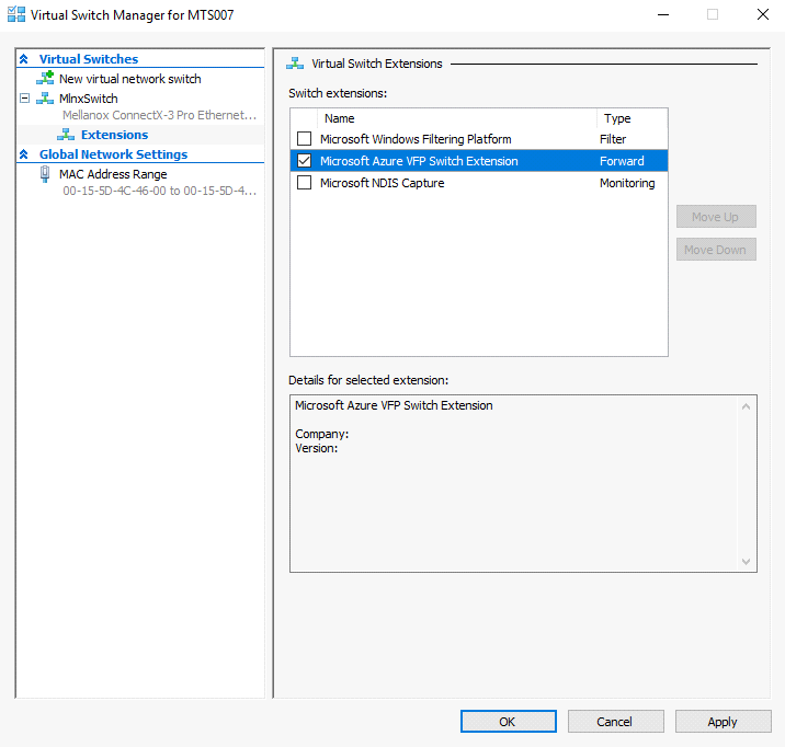
Enable VFP extension:
-
On the vSwitch
PS $ Enable-VMSwitchExtension -VmSwitchName <vSwitchName> -Name "Windows Azure VFP Switch Extension"
Starting from Windows Server 2016, to enable the VFP extension, use the following command instead:
Enable-VMSwitchExtension -VmSwitchName <vSwitchName> -Name "Microsoft Azure VFP Switch Extension"
-
In the Hyper-V Manager: Action->Virtual Switch Manager...
-
-
Shut down the VM.
PS $ Stop-VM -Name <VMName> -Force -Confirm
-
Add a virtual network adapter for the VM.
PS $ Add-VMNetworkAdapter -VMName <VMName> -SwitchName <vSwitchName> -StaticMacAddress <StaticMAC Address>
-
Start the VM.
PS $ Start-VM -Name <VMName>
Since VFP is enabled, without any forwarding rules, it will block all traffic going through the VM.
-
Unblock the traffic, find the port name for the VM.
CMD > vfpctrl /list-vmswitch-port
......
Port name : E431C413-D31F-40EB-AD96-0B2D45FE34AA
Port Friendly name :
Switch name : 8B288106-9DB6-4720-B144-6CC32D53E0EC
Switch Friendly name : MlnxSwitch
PortId : 3
VMQ Usage : 0
SR-IOV Usage : 0
Port type : Synthetic
Port is Initialized.
MAC Learning is Disabled.
NIC name : bd65960d-4215-4a4f-bddc-962a5d0e2fa0--e7199a49-6cca-4d3c-a4cd-22907592527e
NIC Friendly name : testnic
MTU : 1500
MAC address : 00-15-5D-4C-46-00
VM name : vm
......
Command list-vmswitch-port succeeded!
-
Disable the port to allow traffic.
CMD > vfpctrl /disable-port /port <PortName>
Command disable-port succeeded!
The port should be disabled after each reboot of the VM to allow traffic.
Data Plane Development Kit (DPDK)
DPDK is a set of libraries and optimized NIC drivers for fast packet processing in user space. It provides a framework and common API for high speed networking applications.
The WinOF driver supports running DPDK from an SR-IOV virtual machine, see Single Root I/O Virtualization (SR-IOV).
For further information, see NVIDIA®’s DPDK documentation:
-
DPDK Quick Start Guide
-
NVIDIA® DPDK Release Notes
Flows Prerequisites
-
The DPDK flows must have a valid source MAC.
-
The flows’ VLAN is determined by the Hyper-V.
Trunk Mode for VF
To the existing supported Untagged and Access modes, the driver added support for the Trunk mode as well. All these modes can be set with the help of Power Shell command Set-VMNetworkAdapterVlan.
In Trunk mode, the VF can receive and send packets with any vlan_id from the list of allowed VLANs. This list is defined in the parameter AllowedVlanIdList. The user is responsible for adding a VLAN tag to packets on Tx, and handling this tag on Rx.
If the application sends untagged packets, the driver will add a VLAN tag with NativeVlanId on Tx and will strip it on Rx, so that the application at destination will also get untagged traffic.
The value of zero is forbidden for both the Native and the Allowed VLAN identifiers. The Native VLAN ID is expected to be outside the Allowed VLAN ID list.
The below is an example of how to set the Trunk mode with allowed list from 10 to 1000, and a Native VLAN 1200 for VF with MAC 00155D7BDF38:
Get-VMNetworkAdapter -VMName <VM-name> | where -Property MacAddress -eq 00155D7BDF38 | Set-VMNetworkAdapterVlan -Trunk -AllowedVlanIdList 10-1000 -NativeVlanId 1200
Configuring the Trunk Mode for VF
To change the default configuration values, the below Registry parameters should be added to the driver key of the network adapter. They are static, i.e., the driver should be restarted after the change of these parameters.
|
Parameter Name |
Type |
Description |
|---|---|---|
|
TrunkModeForVfEnabled |
dword |
Enable/disable all the feature. The valid values are:
|
|
TrunkModeForVfMaxVlans |
dword |
Max number of VLANs in the allowed list. The valid values are 1-4094 1000: Default |
Important Notes
-
This mode is supported in ConnectX 5 and above adapter cards except for when in BlueField in DPU mode.
-
The feature is supported is Ethernet adapter cards and SR-IOV VFs.
-
Only Linux VMs are supported.
-
Due to a hardware limitation, for ConnectX 4 Lx adapter cards, only the allowed list of VLANs is supported. Trunk VLAN ID should be defined outside the allowed list of VLANs and present a “dummy” VLAN. Meaning one cannot really use it, all packets on this VLAN will be dropped on receive or transmit.
Last updated: