Installation and initialization of the BlueField-3 Platform require attention to the mechanical attributes, power specification, and precautions for electronic equipment.
Safety Warnings
Please observe all safety warnings to avoid injury and prevent damage to system components. Note that not all warnings are relevant to all models.
Note that not all warnings are relevant to all models.

|
General Installation Instructions
|
|
Jewelry Removal Warning
|
|
|
Over-temperature
|
|
|
During Lightning - Electrical Hazard
|
|
|
Copper Cable Connecting/Disconnecting
|
|
|
Equipment Installation
|
|
|
Equipment Disposal
|
|
|
Local and National Electrical Codes
|

|
Hazardous Radiation Exposure
|
For safety warnings in other languages, refer to Safety Warnings.
Installation Procedure Overview
The installation procedure of involves the following steps:
|
Step |
Procedure |
Direct Link |
|---|---|---|
|
1 |
Check the system’s requirements. |
Refer to System Requirements |
|
2 |
Pay attention to the airflow consideration within the host system |
Refer to Airflow Requirements |
|
3 |
Follow the safety precautions |
Refer to Safety |
|
4 |
Unpack the package |
Refer to Unpacking |
|
5 |
Follow the pre-installation checklist |
Refer to Pre-Installation Checklist |
|
7 |
Install the BlueField-3 Platform according to the form-factor you have purchased. |
Refer to Installation Instructions |
|
8 |
(Optional) Replace the bracket form-factor |
Refer to Bracket Replacement Instructions |
|
9 |
Connect cables or modules to the BlueField-3 Platform |
Refer to Cables and Modules |
|
10 |
Power-up the BlueField-3 Platform |
System Requirements
Hardware Requirements
Unless otherwise specified, products are designed to work in an environmentally controlled data center with low levels of gaseous and dust (particulate) contamination.
The operating environment should meet severity level G1 as per ISA 71.04 for gaseous contamination and ISO 14644-1 class 8 for cleanliness level.
The below table lists the motherboard and power supply requirements per BlueField-3 Platform OPN.
|
OPNs |
Power Supply Requirement |
|---|---|
|
A minimum of 75W system power supply through the PCIe x16 interface |
|
Require a supplementary 8-pin ATX power supply connectivity available through the external power supply connector. |
Airflow Requirements
The BlueField-3 BlueField-3 Platform is offered with one airflow direction: from the heatsink to the network ports.
Any use of the product in the opposite airflow direction (from network ports to heatsink) must be validated thermally to ensure proper cooling of the product.
Please refer to the Specifications section for airflow numbers per BlueField-3 Platform model.
Software Requirements
-
Refer to System Requirements section under the Introduction section.
-
Software Stacks - The BlueField-3 Platform is shipped with Ubuntu – a Linux commercial operating system – which includes the NVIDIA OFED stack (MLNX_OFED), and is capable of running all customer-based Linux applications seamlessly. For more information, please refer to the DOCA SDK documentation or NVIDIA BlueField BSP.
Safety Precautions
The BlueField-3 Platform is being installed in a system that operates with voltages that can be lethal. Before opening the case of the system, observe the following precautions to avoid injury and prevent damage to system components.
-
Remove any metallic objects from your hands and wrists.
-
Make sure to use only insulated tools.
-
Verify that the system is powered off and is unplugged.
-
It is strongly recommended to use an ESD strap or other antistatic devices.
Unpacking
Check against the package contents list that all the parts have been sent. Check the parts for visible damage that may have occurred during shipping. Please note that the BlueField-3 Platforms must be placed on an antistatic surface.
Please note that if the BlueField-3 Platform is removed hastily from the antistatic bag, the plastic ziplock may harm the EMI fingers on the networking connector. Carefully remove the BlueField-3 Platform from the antistatic bag to avoid damaging the EMI fingers.
For package contents, please refer to Package Contents.
Pre-Installation Checklist
-
Verify that your system meets the hardware and software requirements stated above.
-
Shut down your system if active.
Turn off the power to the system, and disconnect the power cord. Refer to the system documentation for instructions. Before you install the BlueField-3 Platform, make sure that the system is disconnected from power.
Bracket Replacement Instructions
The BlueField-3 Platform and PCIe Auxiliary Connection card are shipped with an assembled tall or short bracket. If the bracket's form factor is suitable for your requirements, you can skip the remainder of this section and move to Installation Instructions. If you need to replace the bracket's form-factor, please follow the instructions in this section.
During the bracket replacement procedure, do not pull, bend, or damage the cage or EMI fingers. It is recommended to limit bracket replacements to three times.
To replace the bracket you will need the following parts:
-
The new brackets of the proper height
-
The 2 screws saved from the removal of the bracket
Removing the Existing Bracket
-
Using a torque driver, remove the two screws holding the bracket in place.
-
Separate the bracket from the BlueField-3 Platform.
Be careful not to put stress on the LEDs on the BlueField-3 Platform.
-
Save the two screws.
Installing the New Bracket
-
Place the bracket onto theBlueField-3 Platform until the screw holes line up.
Do not force the bracket onto the BlueField-3 Platform.
-
Screw on the bracket using the screws saved from the bracket removal procedure above.
Use a torque driver to apply up to 0.31-0.33 Nm torque on the screws. Ensure you do not pull, bend, or damage the cage or EMI fingers during the process.
Installation Instructions
This section provides detailed instructions on how to install your BlueField-3 Platform in a system.
Choose the installation instructions according to the BlueField-3 Platform configuration you would like to use.
|
OPNs |
Installation Instructions |
|---|---|
|
All BlueField-3 Platforms |
|
|
[Optional] PCIe Extension Connection (2x PCIe x16) Installation Instructions |
Cables and Modules
Networking Cable Installation
-
All cables can be inserted or removed with the unit powered on.
-
To insert a cable, press the connector into the port receptacle until the connector is firmly seated.
-
Support the weight of the cable before connecting the cable to the BlueField-3 Platform. Do this by using a cable holder or tying the cable to the rack.
-
Determine the correct orientation of the connector to the BlueField-3 Platform before inserting the connector. Do not try and insert the connector upside down. This may damage the BlueField-3 Platform.
-
Insert the connector into the BlueField-3 Platform . Be careful to insert the connector straight into the cage. Do not apply any torque, up or down, to the connector cage in the BlueField-3 Platform.
-
Make sure that the connector locks in place.
When installing cables make sure that the latches engage.
Always install and remove cables by pushing or pulling the cable and connector in a straight line with the BlueField-3 Platform.
-
-
After inserting a cable into a port, the Green LED indicator will light when the physical connection is established (that is, when the unit is powered on and a cable is plugged into the port with the other end of the connector plugged into a functioning port). See Networking Ports LEDs interface under the Supported Interfaces section.
-
After plugging in a cable, lock the connector using the latching mechanism particular to the cable vendor. When data is being transferred the Green LED will blink.
-
Make sure not to impede the air exhaust flow through the ventilation holes. Use cable lengths that allow for routing horizontally around to the side of the chassis before bending upward or downward in the rack.
-
To remove a cable, disengage the locks and slowly pull the connector away from the port receptacle. LED indicator will turn off when the cable is unseated.
8-pin ATX Power Supply Cable
The 8-pin ATX power supply cable is mandatory when powering-up the following BlueField-3 Platform. Without a connection to the power supply cable, the DPU will not complete the power on procedure and will not function properly.
-
B3220 Model: 900-9D3B6-00CV-AA0 and 900-9D3B6-00SV-AA0
-
B3240 Model: 900-9D3B6-00CN-AB0 and 900-9D3B6-00SN-AB0
-
B3210 Model: 900-9D3B6-00CC-AA0 and 900-9D3B6-00SC-AA0
-
B3210E Model: 900-9D3B6-00CC-EA0 and 900-9D3B6-00SC-EA0
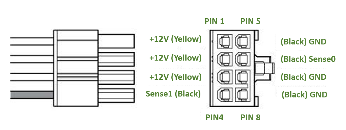
The BlueField-3 DPU includes an 8-pin PCIe ATX power connector that provides additional power supply. While the PCIe slot feeds 66W, the 8-pin PCIe ATX power supply cable provides additional power.
Important Notes and Warnings
-
The BlueField-3 DPU requires a standard PCIe ATX power connection. However, certain servers may require a custom setup to enable ATX power compatibility.
-
Consult the manufacturer's manuals and specifications to ensure proper connectivity.
-
Before connecting the ATX power cable, make sure you are using a PCIe-compliant 8-pin ATX cable from the server power supply kit.
-
Do not link the CPU power cable to the BlueField-3 DPU PCIe ATX power connector, as their pin configurations differ. Using the CPU power cable in this manner is strictly prohibited and can potentially damage the BlueField-3 DPU. Please refer to External PCIe Power Supply Connector Pins for the external PCIe power supply pins.
-
Avoid using non-standard cables that do not comply with the DPU, unnecessary adapter cables, or storing the cables near heat sources.
-
It is preferable that the x16 PCIe golden fingers and the PCI ATX power supply draw from the same power source. For more information on how to power up the card, refer to DPU Power-Up Instructions.
-
The PCIe ATX 8-pin connector is not compatible with an EPS12V power cable source. Ensure that the appropriate PCIe auxiliary power source is available, not an EPS12V power source.
-
If you are uncertain about your server's compatibility with the PCI ATX connection, please contact your NVIDIA representative for assistance.
Wiring Instructions
Cable Installation Instructions
-
Ensure both the system and card are completely powered off for at least 20 seconds before inserting the power connector.
-
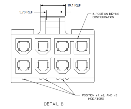
DO NOT force the connector into place; the connectors are “keyed” to fit only one way. Refer to the mechanical keys below for further information.
-
Connect the power supply end of the 8-pin connector to the appropriate receptor on the power supply unit.
-
Apply parallel force when plugging the cable into the power supply connector. Do not bend or twist the cables when plugging or unplugging it.
-
Ensure the cable is fully and securely connected to your DPU and the connector lock is secured.
Mechanical Keys of the 8-pin ATX Power Cable (PCIe CEM Specification Rev 5.0)
Power-Up and Power-Down Sequences
The power-up and power-down sequences listed below apply to BlueField-3 Platforms with x16 PCIe extension option.
-
B3220 Model: 900-9D3B6-00CV-AA0 and 900-9D3B6-00SV-AA0
-
B3240 Model: 900-9D3B6-00CN-AB0 and 900-9D3B6-00SN-AB0
-
B3210 Model: 900-9D3B6-00CC-AA0 and 900-9D3B6-00SC-AA0
-
B3210E Model: 900-9D3B6-00CC-EA0 and 900-9D3B6-00SC-EA0
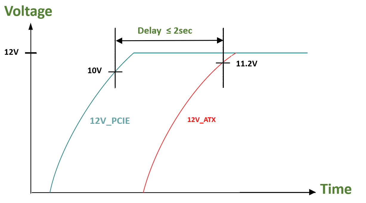
Power-Up Sequence
-
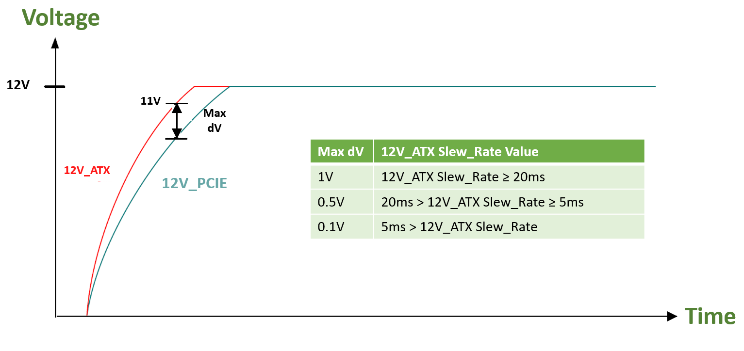
The 12V_ATX voltage can exceed the 12V_PCIE voltage by a maximum allowable voltage difference (dV) when the 12V_ATX reaches 11V. See below graph and table describing the dV between the 12V_ATX and 12V_PCIE voltages.
-
The 12V_ATX can be powered up after the 12V_PCIE, with a maximum delay of 2 seconds. The below graph illustrates the delay between the 12V_ATX and 12V_PCIE voltages at power-up.
Power-Down Sequence
-
The 12V_PCIE voltage can be powered down simultaneously with the 12V_ATX voltage, or within a maximum delay of 200usec. The below graph illustrates the delay between the 12V_ATX and 12V_PCIE voltages at power-down.
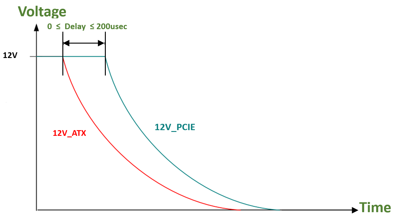
-
The 12V_PCIE voltage must not be powered down while the 12V_ATX voltage is powered up.
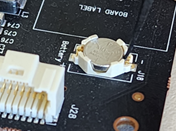
Battery Removal Instructions
This is a general guide on how to remove the coin type Lithium battery mounted on the BlueField-3 platforms.
Disclaimer: These guidelines are intended to prevent damaging the product, voiding the warranty, and/or creating safety hazards.
Handle the product with care; avoid touching the electronic components on the card like the heatsink, connectors and PCIe golden fingers during the battery removal procedure.
The following figures are for illustration purposes only. Different card models may have different variation / locations of the battery holder. For the battery location of each BlueField-3 model, refer to Supported Interfaces.
-
Step 1: Prepare Your Workspace:
Ensure you are working in a well-lit and static-free environment.
Gather the necessary tools, such as spudger or a small non-conductive tool and an antistatic wrist strap. -
Step 2: Power Off and Disconnect:
Power off the BlueField-3 platform and disconnect it from any power source.
Disconnect all cables and peripherals connected to the device. -
Step 3: Ground Yourself:
Wear an antistatic wrist strap to prevent the buildup of static electricity, which can damage electronic components. -
Step 4: Identify the Battery:
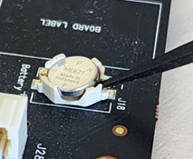
Locate the battery on the platform. It is a small, round, silver coin type Lithium battery (CR621) mounted on a battery holder. Please note that the location of the battery holder may vary between different card variations.
-
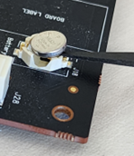
Step 5: Remove the Battery:
Using a plastic spudger or a small non-conductive tool, insert the tool into the side of the battery holder marked with a “-” (minus).
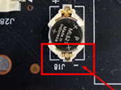
Gently pry the battery from its holder.
-
Step 6: Dispose of the Battery Properly: Used batteries should be recycled according to local regulations.
-
Step 7: Power up the platform: Refer to the product documentation for instructions.
Last updated: