This document describes how to use DPUServiceChain in DPF.
Introduction
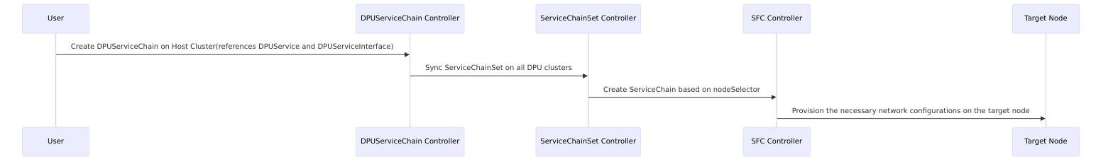
The purpose of DPUServiceChain is to allow user to define how to steer traffic on DPU through DPUServiceInterfaces. The following controllers are used internally to achieve this.
-
User creates DPUServiceChain, servicechaincontroller consumes it on the host cluster.
-
ServiceChainSet is created on DPU clusters
-
ServiceChain is created for individual nodes based on nodeSelector.
-
SFC controller provisions the necessary network configurations on DPU.
How to Use DPUServiceChain
DPUServiceChain example:
The following YAML manifest defines a DPUServiceChain named example-chain and refers to one DPUService named example-service and 4 DPUServiceInterfaces. DPUServiceChain will define how the traffic will flow through those DPUServiceInterfaces.
DPUServiceInterfaces
apiVersion: svc.dpu.nvidia.com/v1alpha1
kind: DPUServiceInterface
metadata:
  name: p0
  namespace: dpf-operator-system
spec:
  template:
    spec:
      template:
        metadata:
          labels:
            uplink: "p0"
        spec:
          interfaceType: physical
          physical:
            interfaceName: p0
apiVersion: svc.dpu.nvidia.com/v1alpha1
kind: DPUServiceInterface
metadata:
  name: pf0hpf
  namespace: dpf-operator-system
spec:
  template:
    spec:
      nodeSelector:
        matchExpressions:
          - key: kubernetes.io/os
            operator: In
            values:
              - "linux"
      template:
        metadata:
          labels:
            uplink: "pf0hpf"
        spec:
          interfaceType: pf
          pf:
            pfID: 0
apiVersion: svc.dpu.nvidia.com/v1alpha1
kind: DPUServiceInterface
metadata:
  name: eth1
  namespace: dpf-operator-system
spec:
  template:
    spec:
      template:
        metadata:
          labels:
            svc.dpu.nvidia.com/interface: "eth1"
            svc.dpu.nvidia.com/service: example-service
        spec:
          interfaceType: service
          service:
            serviceID: example-service
            network: mybrsfc
            interfaceName: eth1
apiVersion: svc.dpu.nvidia.com/v1alpha1
kind: DPUServiceInterface
metadata:
  name: eth2
  namespace: dpf-operator-system
spec:
  template:
    spec:
      template:
        metadata:
          labels:
            svc.dpu.nvidia.com/interface: "eth2"
            svc.dpu.nvidia.com/service: example-service
        spec:
          interfaceType: service
          service:
            serviceID: example-service
            network: mybrsfc
            interfaceName: eth2
DPUService
apiVersion: svc.dpu.nvidia.com/v1alpha1
kind: DPUService
metadata:
  name: example-service
  namespace: dpf-operator-system
spec:
  serviceID: example-service
  interfaces:
    - eth1
    - eth2
  helmChart:
    source:
      repoURL: https://helm.ngc.nvidia.com/nvidia/doca
      version: 1.0.1
      chart: example-service
    values:
      resources:
        memory: 6Gi
DPUServiceChain
apiVersion: svc.dpu.nvidia.com/v1alpha1
kind: DPUServiceChain
metadata:
  name: example-chain
  namespace: dpf-operator-system
spec:
  template:
    spec:
      template:
        spec:
          switches:
            - ports:
                - serviceInterface:
                    matchLabels:
                      uplink: p0
                - serviceInterface:
                    matchLabels:
                      svc.dpu.nvidia.com/service: example-service
                      svc.dpu.nvidia.com/interface: eth1
            - ports:
                - serviceInterface:
                    matchLabels:
                      svc.dpu.nvidia.com/service: example-service
                      svc.dpu.nvidia.com/interface: eth2
                - serviceInterface:
                    matchLabels:
                      uplink: pf0hpf
              serviceMTU: 2000
Let's break it down step by step.
-
There are 4 DPUServiceInterfaces
-
uplink port p0
-
uplink port pf0hpf on host
-
service interface eth1
-
service interface eth2
-
-
There is one DPUService
-
example-service which has two interfaces eth1 and eth2
-
-
There is one DPUServiceChain
-
example-chain
p0 --> eth1 --> eth2 --> pf0hpf
-
-
On the switches object there is
serviceMTUwhich defines the MTU between services in the DPU cluster-
The default value for this MTU is 1500
-
NOTE: This only affects services on the DPU, it should be aligned with the general MTU set for the traffic in the network
-
NOTE: that when changed, it will restart every pod that relates to this switch
-
In the above example, traffic will flow from uplink port p0 to example DPU service's eth1 iface. From eth1 iface, it will go to eth2 iface(eth1->eth2 is handled by the service itself and not by the chain) and then to uplink port pf0hpf on the host.
Last updated: