

Updated Jul 1, 2026 to v26.4 GA.
Scope
This Reference Deployment Guide (RDG) offers comprehensive instructions for deploying the NVIDIA DOCA Platform Framework (DPF) on high-performance, bare-metal infrastructure in Zero-Trust mode. The guide focuses on deploying the NVIDIA DOCA SNAP service in virtio-fs mode on NVIDIA® BlueField®-3 DPUs to deliver secure, isolated, and hardware-accelerated environments.
This guide is designed for experienced system administrators, system engineers, and solution architects looking to provision highly secure bare-metal environments backed by NFS storage. We will take full advantage of NVIDIA DPU hardware acceleration and offload capabilities, maximizing datacenter workload efficiency and performance.
-
This reference implementation, as the name suggests, is a concrete, subjective deployment example designed to solve the problem described above.
-
While there may be other approaches to implementing similar solutions, this document provides detailed guidance on this particular method.
Abbreviations and Acronyms
|
Term |
Definition |
Term |
Definition |
|---|---|---|---|
|
BFB |
BlueField Bootstream |
NFS |
Network File System |
|
BGP |
Border Gateway Protocol |
PVC |
Persistent Volume Claim |
|
CNI |
Container Network Interface |
RDG |
Reference Deployment Guide |
|
CRD |
Custom Resource Definition |
RDMA |
Remote Direct Memory Access |
|
CSI |
Container Storage Interface |
SF |
Scalable Function |
|
DOCA |
Data Center Infrastructure-on-a-Chip Architecture |
SFC |
Service Function Chaining |
|
DOCA SNAP |
NVIDIA® DOCA™ Storage-Defined Network Accelerated Processing |
SR-IOV |
Single Root Input/Output Virtualization |
|
DPF |
DOCA Platform Framework |
TOR |
Top of Rack |
|
DPU |
Data Processing Unit |
VF |
Virtual Function |
|
HBN |
Host-Based Networking |
VLAN |
Virtual Local Area Network |
|
IPAM |
IP Address Management |
VRR |
Virtual Router Redundancy |
|
K8S |
Kubernetes |
VTEP |
Virtual Tunnel End Point |
|
MAAS |
Metal as a Service |
VXLAN |
Virtual Extensible LAN |
Introduction
The NVIDIA BlueField-3 Data Processing Unit is a powerful infrastructure compute platform designed for high-speed processing of software-defined networking, storage, and cybersecurity. With a capacity of 400 Gb/s, BlueField-3 combines robust computing, high-speed networking, and extensive programmability to deliver hardware-accelerated, software-defined solutions for demanding workloads.
Deploying and managing DPUs and their associated DOCA services, especially at scale, can be quite challenging. Without a proper provisioning and orchestration system, handling the DPU lifecycle and configuring DOCA services places a heavy operational burden on system administrators. The NVIDIA DOCA Platform Foundation addresses this challenge by streamlining and automating the lifecycle management of DOCA services.
NVIDIA DOCA unlocks the full potential of the BlueField platform, enabling rapid development of applications and services that offload, accelerate, and isolate data center workloads. One such example is NVIDIA DOCA SNAP, a DPU storage service that is designed to accelerate and optimize storage protocols by leveraging the capabilities of NVIDIA's BlueField DPUs. NVIDIA DOCA SNAP technology encompasses a family of services that enable hardware-accelerated virtualization of local storage running on NVIDIA BlueField products. The DOCA SNAP service presents NFS-based networked storage as a local volume to the host, emulated by the DOCA SNAP service on the DPU. At its core, DOCA SNAP enables high-performance, low-latency access to storage by allowing applications to interact directly with raw remote file system volume - bypassing traditional filesystem overhead. As part of the DPF deployment model, the DOCA SNAP solution is composed of multiple functional components packaged into containers, which are deployed across both the x86 Kubernetes management and DPU Kubernetes clusters.
This reference implementation leverages open-source components and provides an end-to-end walkthrough of the deployment process, including:
-
Infrastructure provisioning with MAAS
-
Integration with NVIDIA’s DPF
-
Deployment and orchestration of DPU-based services inside the Kubernetes cluster
-
Configuration of BlueField devices with enabled NFS (virtio-fs) emulation for DOCA SNAP service
-
Management of DPU resources and workloads using Kubernetes-native constructs
This guide provides a comprehensive, practical example of installing the DPF system with the NVIDIA DOCA SNAP service on a Kubernetes cluster according to the "Storage Development Guide".
In our guide, we used the NFS server as an example of a storage backend service.
This storage backend service is used only for demonstration purposes and is not intended or supported for production use cases.
References
Solution Architecture
Key Components and Technologies
-
NVIDIA BlueField® Data Processing Unit (DPU)
The NVIDIA® BlueField® data processing unit (DPU) ignites unprecedented innovation for modern data centers and supercomputing clusters. With its robust compute power and integrated software-defined hardware accelerators for networking, storage, and security, BlueField creates a secure and accelerated infrastructure for any workload in any environment, ushering in a new era of accelerated computing and AI.
-
NVIDIA DOCA Software Framework
NVIDIA DOCA™ unlocks the potential of the NVIDIA® BlueField® networking platform. By harnessing the power of BlueField DPUs and SuperNICs, DOCA enables the rapid creation of applications and services that offload, accelerate, and isolate data center workloads. It lets developers create software-defined, cloud-native, DPU- and SuperNIC-accelerated services with zero-trust protection, addressing the performance and security demands of modern data centers.
-
NVIDIA ConnectX SmartNICs
10/25/40/50/100/200 and 400G Ethernet Network Adapters
The industry-leading NVIDIA® ConnectX® family of smart network interface cards (SmartNICs) offer advanced hardware offloads and accelerations.
NVIDIA Ethernet adapters enable the highest ROI and lowest Total Cost of Ownership for hyperscale, public and private clouds, storage, machine learning, AI, big data, and telco platforms.
-
NVIDIA LinkX Cables
The NVIDIA® LinkX® product family of cables and transceivers provides the industry’s most complete line of 10, 25, 40, 50, 100, 200, and 400GbE in Ethernet and 100, 200 and 400Gb/s InfiniBand products for Cloud, HPC, hyperscale, Enterprise, telco, storage and artificial intelligence, data center applications.
-
NVIDIA Spectrum Ethernet Switches
Flexible form-factors with 16 to 128 physical ports, supporting 1GbE through 400GbE speeds.
Based on a ground-breaking silicon technology optimized for performance and scalability, NVIDIA Spectrum switches are ideal for building high-performance, cost-effective, and efficient Cloud Data Center Networks, Ethernet Storage Fabric, and Deep Learning Interconnects.
NVIDIA combines the benefits of NVIDIA Spectrum™ switches, based on an industry-leading application-specific integrated circuit (ASIC) technology, with a wide variety of modern network operating system choices, including NVIDIA Cumulus® Linux, SONiC and NVIDIA Onyx®.
-
NVIDIA Cumulus Linux
NVIDIA® Cumulus® Linux is the industry's most innovative open network operating system that allows you to automate, customize, and scale your data center network like no other.
-
Kubernetes
Kubernetes is an open-source container orchestration platform for deployment automation, scaling, and management of containerized applications.
-
Kubespray
Kubespray is a composition ofAnsible
playbooks, inventory, provisioning tools, and domain knowledge for generic OS/Kubernetes clusters configuration management tasks and provides:
-
A highly available cluster
-
Composable attributes
-
Support for most popular Linux distributions
-
-
RDMA
RDMA is a technology that allows computers in a network to exchange data without involving the processor, cache or operating system of either computer.
Like locally based DMA, RDMA improves throughput and performance and frees up compute resources.
Solution Design
Solution Logical Design
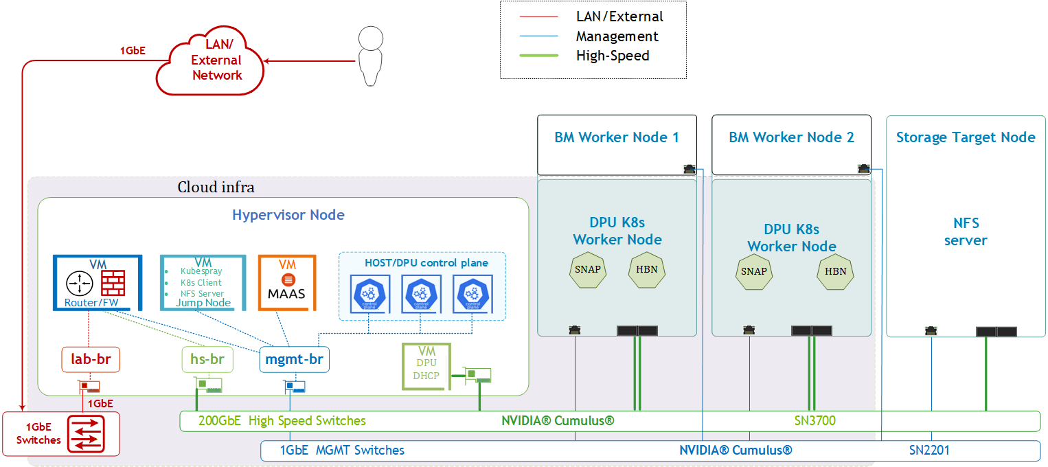
The logical design includes the following components:
-
1 x Hypervisor node (KVM based) with ConnectX-7
-
1 x Firewall VM
-
1 x Jump VM
-
1 x MAAS VM
-
3 x VMs running all K8s management components for Host/DPU clusters
-
1 x DPU DHCP VM (used passthrough host NIC)
-
-
2 x Worker nodes, each with a 1 x BlueField-3 NIC
-
Storage Target Node with ConnectX-7 and NFS server apps
-
Single 200 GbE High-Speed (HS) switch
-
1 GbE Host Management network
SFC Logical Diagram
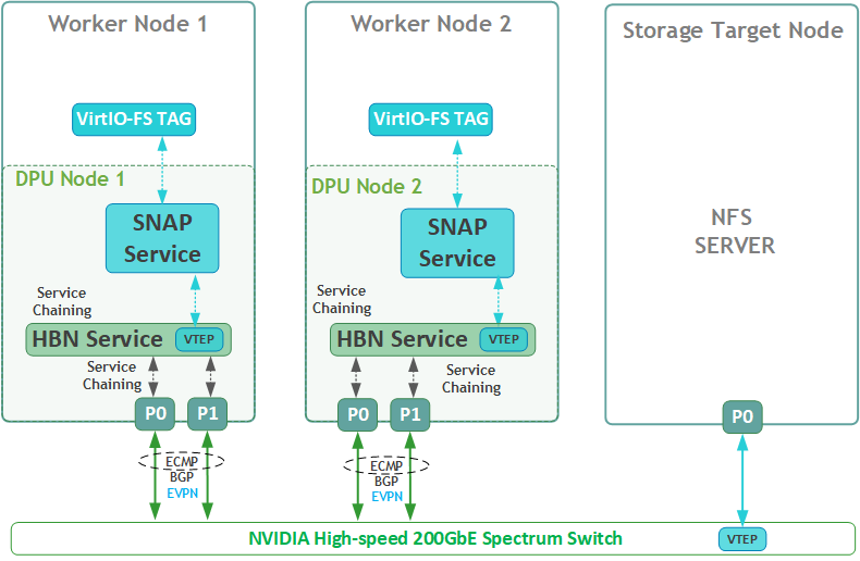
The DOCA Platform Framework simplifies DPU management by providing orchestration through a K8s API. It handles the provisioning and lifecycle management of DPUs, orchestrates specialized DPU services, and automates service function chaining (SFC) tasks. This ensures seamless deployment of NVIDIA DOCA services, enabling efficient offloading and routing of traffic across the HBN data plane. The SFC logic diagram implemented in this guide is presented below.
Volume Emulation Logical Diagram
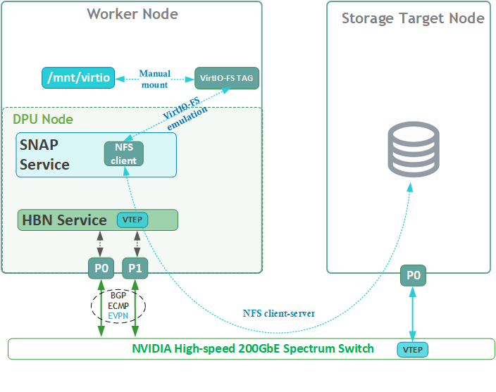
The following logical diagram demonstrates the main components involved in a volume mount procedure to tenant host.
Upon receiving a new request for an emulated VIRTIO-FS volume, DOCA SNAP components bring a NFS volume via SNAP NFS client to the required DPU K8s worker node. The DPU then emulates it as a VIRTIO-FS volume to mount (manual procedure) on the same x86 host.
Firewall Design
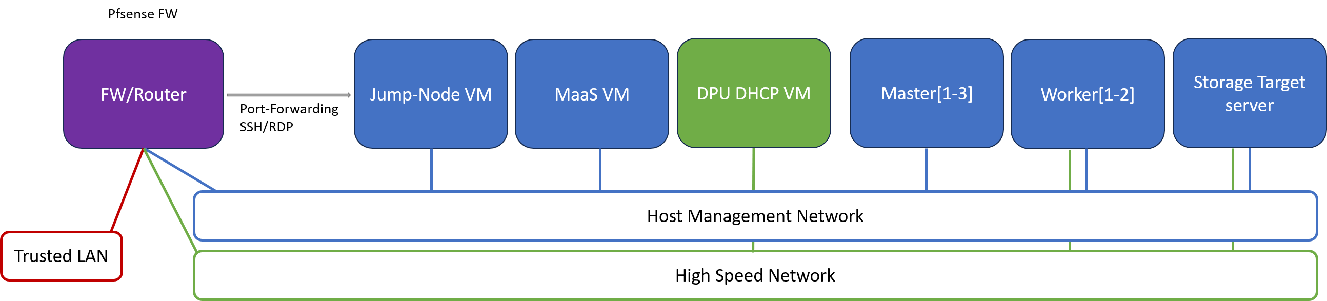
The pfSense firewall in this solution serves a dual purpose:
-
Firewall – Provides an isolated environment for the DPF system, ensuring secure operations
-
Router – Enables internet access and connectivity between the host management network and the high-speed network
Port-forwarding rules for SSH and RDP are configured on the firewall to route traffic to the jump node’s IP address in the host management network. From the jump node, administrators can manage and access various devices in the setup, as well as handle the deployment of the Kubernetes (K8s) cluster and DPF components.
The following diagram illustrates the firewall design used in this solution:
Software Stack Components
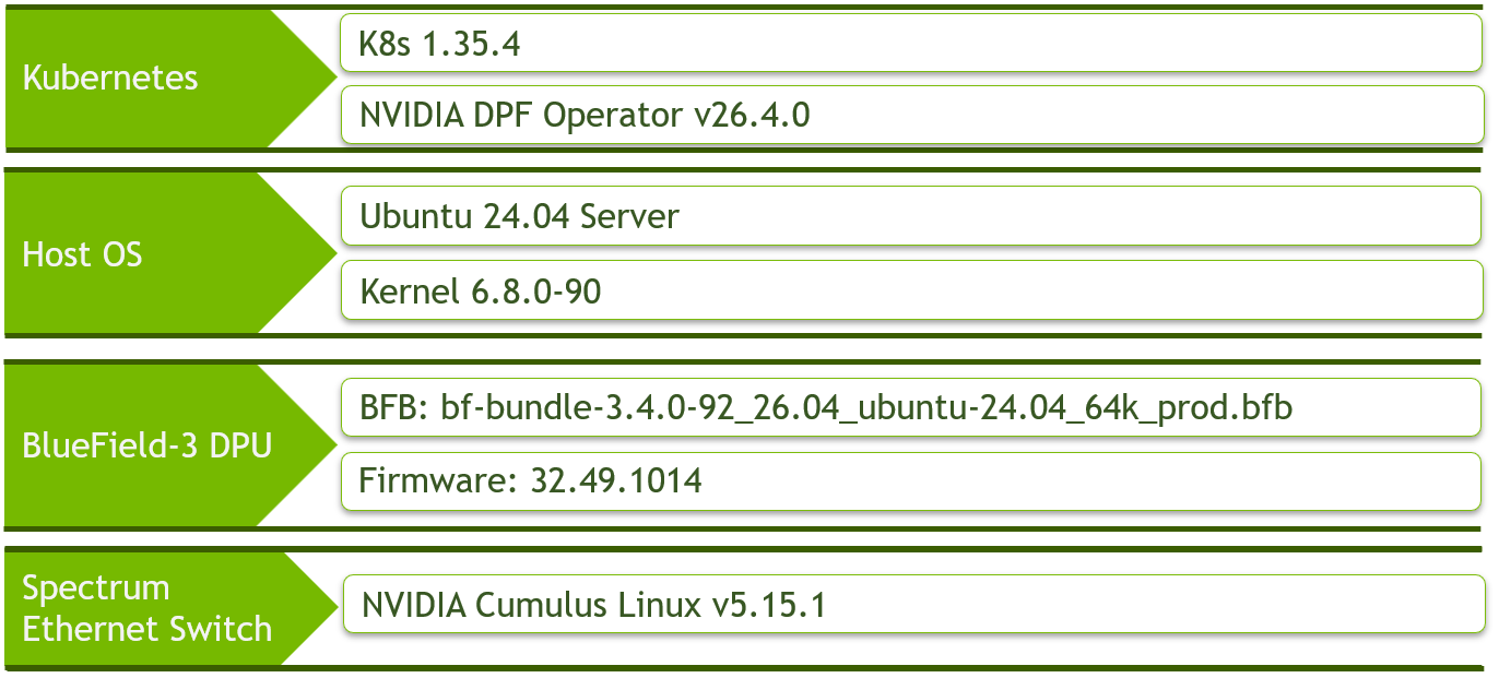
Be sure to use the same software versions as described above.
Bill of Materials
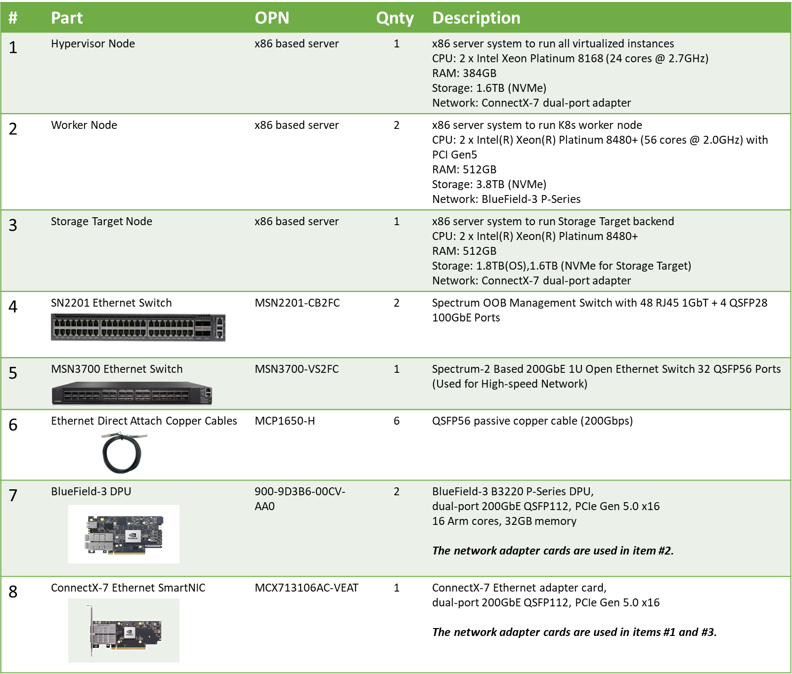
Deployment and Configuration
Node and Switch Definitions
These are the definitions and parameters used for deploying the demonstrated fabric:
|
Switch Port Usage |
||
|
|
1 |
swp1-6 |
|
|
1 |
swp1,2,11-14,32 |
|
Hosts |
|||||
|---|---|---|---|---|---|
|
Rack |
Server Type |
Server Name |
Switch Port |
IP and NICs |
Default Gateway |
|
Rack1
|
Hypervisor Node |
|
hs-switch: |
lab-br (interface eno1): Trusted LAN IP mgmt-br (interface eno2): - hs-br (interface ens2f0np0): |
Trusted LAN GW |
|
Rack1
|
Storage Target Node |
|
mgmt-switch: hs-switch: |
enp1s0f0: 10.0.110.25/24 enp144s0f0np0: 10.0.124.1/24 |
10.0.110.254 |
|
Rack1
|
Worker Node |
|
mgmt-switch: hs-switch:
|
ens15f0: 10.0.110.21/24 ens5f0np0/ens5f1np1: 10.0.120.0/22
|
10.0.110.254 |
|
Rack1
|
Worker Node |
|
mgmt-switch: hs-switch:
|
ens15f0: 10.0.110.22/24 ens5f0np0/ens5f1np1: 10.0.120.0/22
|
10.0.110.254 |
|
Rack1 |
Firewall (Virtual) |
|
- |
WAN (lab-br): Trusted LAN IP LAN (mgmt-br): 10.0.110.254/24 OPT1 (hs-br): 172.169.50.1/30 |
Trusted LAN GW |
|
Rack1
|
Jump Node (Virtual) |
|
- |
enp1s0: 10.0.110.253/24 |
10.0.110.254 |
|
Rack1
|
MAAS (Virtual) |
|
- |
enp1s0: 10.0.110.252/24 |
10.0.110.254 |
|
Rack1 |
DPU DHCP (Virtual) |
|
- |
enp1s0: 10.0.125.1/24 |
10.0.125.254 |
|
Rack1
|
Master Node (Virtual) |
|
- |
enp1s0: 10.0.110.1/24 |
10.0.110.254 |
|
Rack1
|
Master Node (Virtual) |
|
- |
enp1s0: 10.0.110.2/24 |
10.0.110.254 |
|
Rack1
|
Master Node (Virtual) |
|
- |
enp1s0: 10.0.110.3/24 |
10.0.110.254 |
Wiring
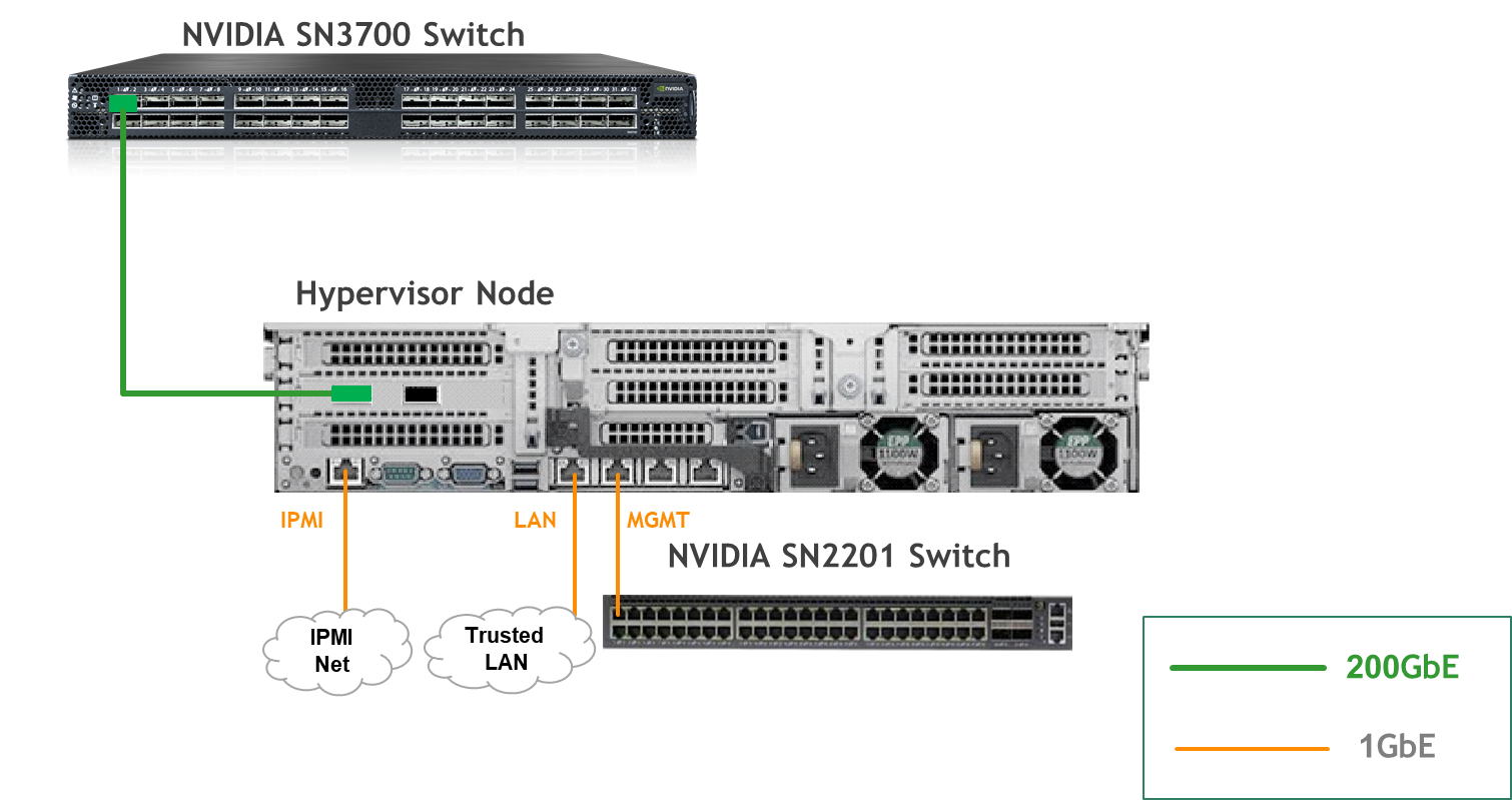
Hypervisor Node
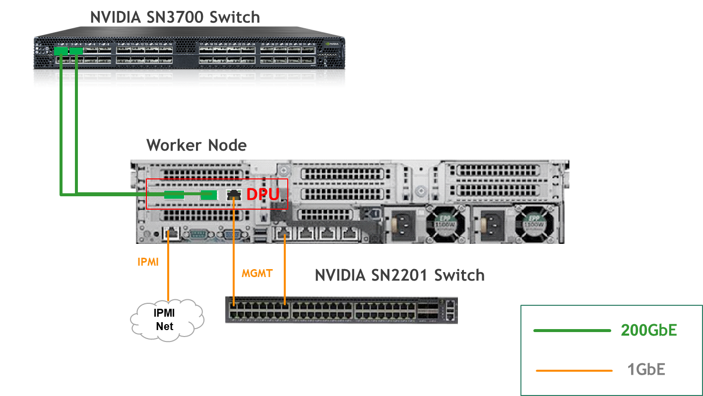
Bare Metal Worker Node
Storage Target Node
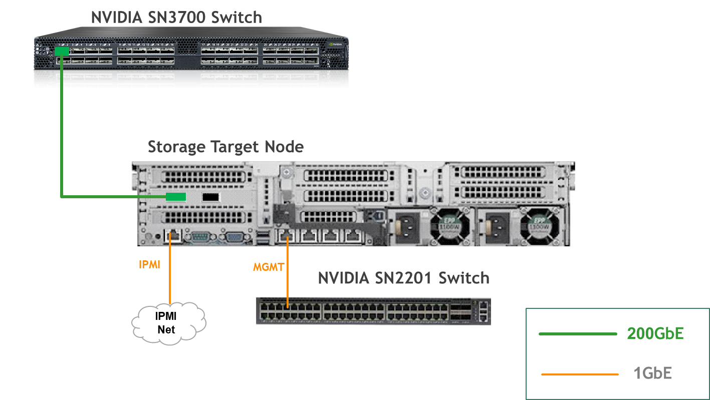
Fabric Configuration
Updating Cumulus Linux
As a best practice, make sure to use the latest released version of Cumulus Linux NOS.
For information on upgrading Cumulus Linux, refer to the Cumulus Linux User Guide.
Configuring the Cumulus Linux Switch
The SN3700 switch (hs-switch) is configured as follows:
-
The following commands configure BGP unnumbered on
hs-switch. -
Cumulus Linux enables the BGP equal-cost multipathing (ECMP) option by default.
The SN2201 switch (mgmt-switch) is configured as follows:
Installation and Configuration
Make sure that the BIOS settings on the worker node servers have SR-IOV enabled and that the servers are tuned for maximum performance.
All worker nodes must have the same PCIe placement for the BlueField-3 NIC and must display the same interface name.
Make sure that you have DPU BMC and OOB MAC addresses.
Use this Reference Deployment Guide (RDG) for:
-
Host Configuration,
-
K8s Cluster Deployment and Configuration,
-
DPF Installation
Base infrastructure updated
The current use case requires updates to both the firewall and MAAS configurations to enable successful deployment.
A static route for 10.0.125.0/24 must be added to the firewall, following the same configuration as the existing route for 10.0.120.0/22.
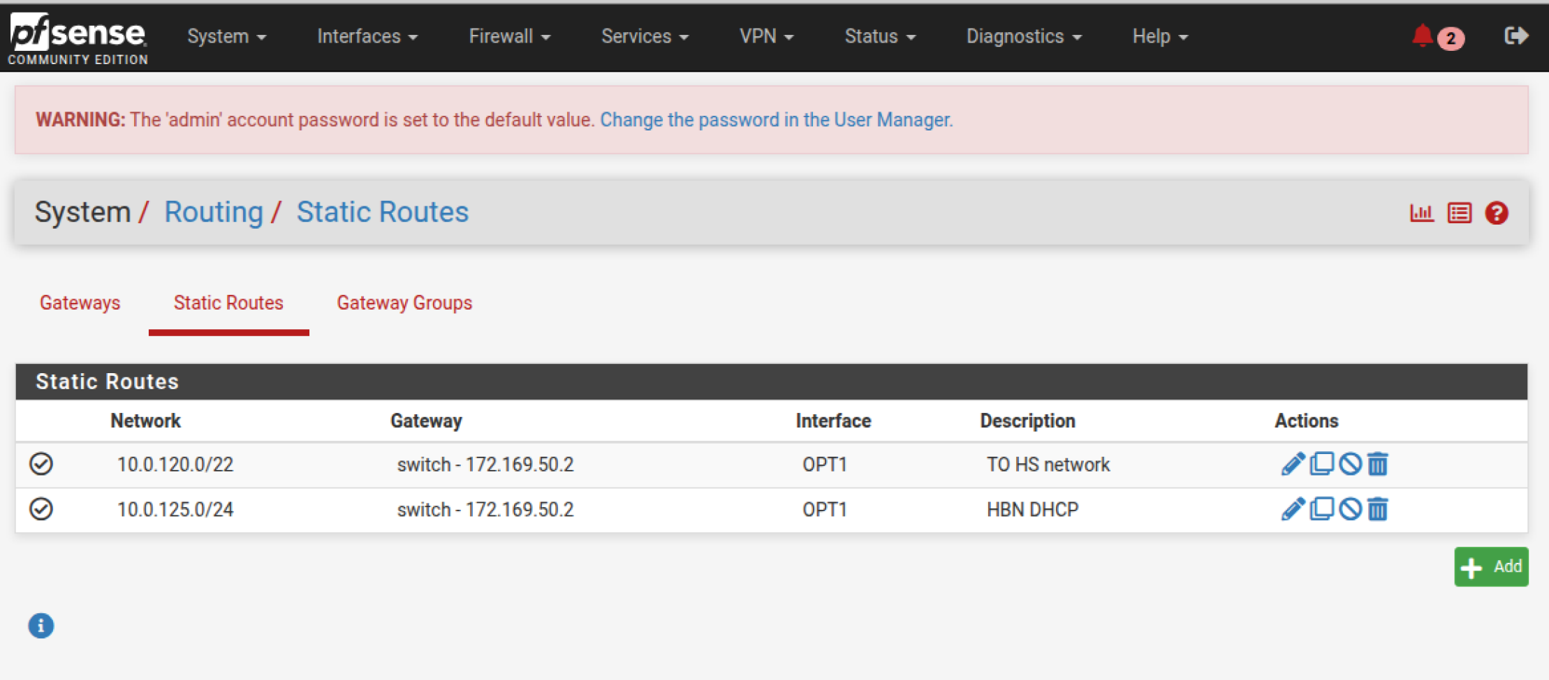
Extend the MAAS DNS configuration to support DNS resolution for the additional subnets.
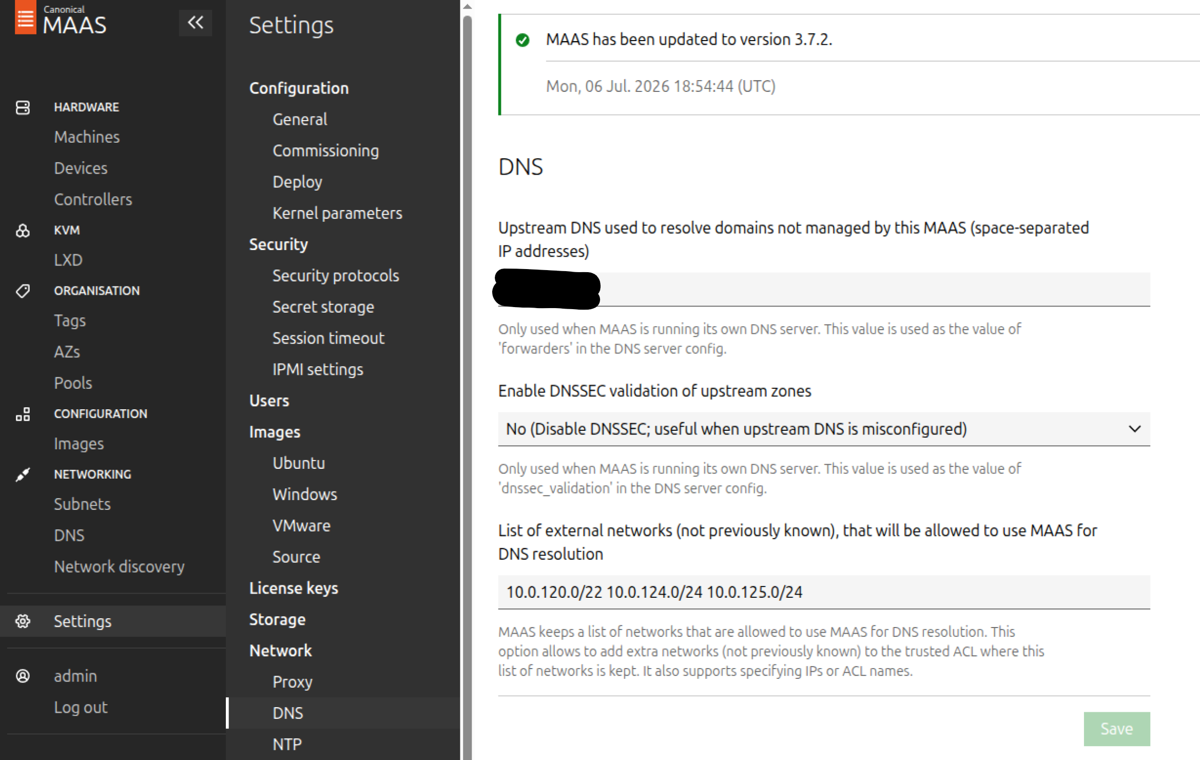
Provisioning "DPU DHCP VM"
-
Please install Rocky Linux 9.0 in a minimal server configuration.
-
Configure the IP address to 10.0.125.1/24 with default GW 10.0.125.254/24 and your preferred DNS server.
-
Connect to the VM and install the following modules:
sudo dnf -y update sudo dnf install -y lldpd dnsmasq -
Apply the following DNSMASQ configuration in the file /etc/dnsmasq.conf.
The following dnsmasq configuration is customized for our specific deployment use case and should not be used as a default configuration.# #Disable the DNS server set: port=0 # port=53 # #Setup the server to be your authoritative DHCP server # dhcp-authoritative # #Set the DHCP server to hand addresses sequentially # dhcp-sequential-ip # #Enable more detailed logging for DHCP # log-dhcp log-queries no-resolv log-facility=/var/log/dnsmasq.log domain=x86.dpf.rdg.local.domain local=/x86.dpf.rdg.local.domain/ server=8.8.8.8 listen-address=10.0.125.1,127.0.0.1 # #Create different dhcp scopes for each of the three simulated subnets here, using tags for ID #Format is: dhcp-range=<your_tag_here>,<start_of_scope>,<end_of_scope>,<subnet_mask>,<lease_time> # dhcp-range=subnet0,10.0.120.2,10.0.120.6,255.255.255.248,8h dhcp-option=subnet0,42,192.114.62.250 dhcp-option=subnet0,6,10.0.125.1 dhcp-option=subnet0,3,10.0.120.1 dhcp-range=subnet1,10.0.120.10,10.0.120.14,255.255.255.248,8h dhcp-option=subnet1,42,192.114.62.250 dhcp-option=subnet1,6,10.0.125.1 dhcp-option=subnet1,3,10.0.120.9
-
Start and enable autostart for dnsmasq.service.
sudo systemctl start dnsmasq.service sudo systemctl enable dnsmasq.service -
Check service status
sudo systemctl status dnsmasq.service
### Command output should look like: ###
 dnsmasq.service - DNS caching server.
     Loaded: loaded (/usr/lib/systemd/system/dnsmasq.service; enabled; preset: disabled)
     Active: active (running) since Sun 2026-07-12 13:40:59 UTC; 1 day 22h ago
 Invocation: ced747f062214acea30862c82e0cca2e
    Process: 997 ExecStart=/usr/sbin/dnsmasq (code=exited, status=0/SUCCESS)
   Main PID: 1010 (dnsmasq)
      Tasks: 1 (limit: 23090)
     Memory: 1.2M (peak: 1.9M)
        CPU: 8ms
     CGroup: /system.slice/dnsmasq.service
             ??1010 /usr/sbin/dnsmasq

Jul 12 13:40:59 dhcp-hbn.dpf.rdg.local.domain systemd[1]: Starting dnsmasq.service - DNS caching server....
Jul 12 13:40:59 dhcp-hbn.dpf.rdg.local.domain systemd[1]: Started dnsmasq.service - DNS caching server..
Storage Target Configuration
-
The Storage target node is a separate, manually configured node in this RDG.
Procedure:
-
Perform a regular Ubuntu 24.04 installation on the Storage target VM.
-
Create the following Netplan configuration to enable internet connectivity, DNS resolution and set an IP in the storage high-speed subnet:
Replace
enp1s0andenp5s0np1with your interface names.YAMLnetwork: version: 2 ethernets: enp1s0: addresses: - "10.0.110.25/24" mtu: 9000 nameservers: addresses: - 10.0.110.252 search: - dpf.rdg.local.domain routes: - to: "default" via: "10.0.110.254" enp5s0np1: addresses: - "10.0.124.1/24" mtu: 9000 -
Apply the netplan configuration:
depuser@storage-target:~$ sudo netplan apply -
Update and upgrade the system:
sudo apt update -y sudo apt upgrade -y -
Create XFS file system on the NVMe disk and mount it on
/srv/nfsdirectory:Replace
/dev/nvme0n1with your device name.sudo mkfs.xfs /dev/nvme0n1 sudo mkdir -m 777 /srv/nfs/ sudo mount /dev/nvme0n1 /srv/nfs/ -
Set the mount to be persistent:
$ sudo blkid /dev/nvme0n1 /dev/nvme0n1: UUID="b37df0a9-d741-4222-82c9-7a3d66ffc0e1" BLOCK_SIZE="512" TYPE="xfs" $ echo "/dev/disk/by-uuid/b37df0a9-d741-4222-82c9-7a3d66ffc0e1 /srv/nfs xfs defaults 0 1" | sudo tee -a /etc/fstab -
Install and configure an NFS server with the
/srv/nfsdirectory:sudo apt install -y nfs-server echo "/srv/nfs/ 10.0.110.0/24(rw,sync,no_subtree_check)" | sudo tee -a /etc/exports echo "/srv/nfs/ 10.0.124.0/24(rw,sync,no_subtree_check)" | sudo tee -a /etc/exports -
Restart the NFS server:
sudo systemctl restart nfs-server -
Create the directory
shareunder/srv/nfswith the same permissions as the parent directory:sudo mkdir -m 777 /srv/nfs/share
DPU Service Installation
Prerequisites
Before starting the deployment, a few adjustments are required.
Add additional routing on each K8s control plane node to the Target node:
To apply the updated configuration, run the following command:
netplan apply
SNAP VirtioFS service deployment
-
Clone the repo from github.com/NVIDIA/doca-platform and move to the
docs/public/user-guides/zero-trust/use-cases/hbn-snapdirectory. -
Modify the variables in
manifests/00-env-vars/envvars.envto fit your environment, then source the file:
Replace the values for the variables in the following file with the values that fit your setup. Specifically, pay attention to DPUCLUSTER_INTERFACE and BMC_ROOT_PASSWORD.
It is necessary to set several environment variables before running this command.
$ source manifests/00-env-vars/envvars.env
Change the DPUDeployment, DPUServiceConfig, DPUServiceTemplate and other necessary objects.
Before deploying the objects under the manifests/03.2-dpudeployment-installation-virtiofs/directory, a few adjustments need to be made.
-
Modify configuration file
dpudeployment.yaml:
-
Modify configuration file
hbn-dpuserviceconfig.yaml:
-
Modify configuration file
hbn-dpuservicetemplate.yaml:
-
Modify configuration file
hbn-ipam.yaml:
Create Vendor CSI Controller Credentials
Create the credential request for the NFS CSI Controller before installing the chart:
kubectl apply -f manifests/03.2-dpudeployment-installation-virtiofs/credentials/
Install SNAP Host Controller on the Host Cluster
Install the SNAP Host Controller that runs on the host cluster for this scenario:
helm repo add --force-update dpf-repository ${REGISTRY}
helm repo update
helm upgrade --install -n dpf-operator-system snap-host-controller \
  dpf-repository/dpf-storage --version=$TAG \
  --wait \
  -f manifests/03.2-dpudeployment-installation-virtiofs/helm-values/snap-host-controller.yml
Install NFS CSI Controller on the Host Cluster
Install the NFS CSI Controller that runs on the host cluster for this scenario:
helm upgrade --install -n dpf-operator-system nfs-csi-controller \
  oci://ghcr.io/mellanox/dpf-storage-vendors-charts/nfs-csi-controller --version=v0.2.0 \
  --wait \
  -f manifests/03.2-dpudeployment-installation-virtiofs/helm-values/nfs-csi-controller.yml
Apply DPU-side Storage Resources
Warning
In case more than 1 DPU exists per node, the relevant selector should be applied in the DPUDeployment to select the appropriate DPU. See DPUDeployment - DPUs Configuration to understand more about the selectors.
cat manifests/03.2-dpudeployment-installation-virtiofs/*.yaml | envsubst | kubectl apply -f -
This will deploy the following objects:
BFB to download Bluefield Bitstream to a shared volume
DPUFlavor with VirtioFS Storage config
DPUDeployment for VirtioFS Storage
DPUServiceIPAM
DPUServiceConfiguration and DPUServiceTemplate for DOCA HBN
DPUServiceNAD for storage services (no RDMA CNI chaining)
DPUServiceConfiguration and DPUServiceTemplate for DOCA SNAP
DPUServiceConfiguration and DPUServiceTemplate for SNAP Node Driver
DPUServiceConfiguration and DPUServiceTemplate for FS Storage DPU Plugin
DPUServiceConfiguration and DPUServiceTemplate for NFS CSI Controller on DPU
Verification
These verification commands may need to be run multiple times to ensure the condition is met.
Note that the DPUService name will have a random suffix. For example, doca-hbn-l2xsl.
Verify the DPU and Service installation with:
## Ensure the BFB is ready
kubectl wait --for=jsonpath='{.status.phase}'=Ready --namespace dpf-operator-system bfb bf-bundle-$TAG --timeout=600s
## Ensure the DPUServices are created and have been reconciled.
kubectl wait --for=condition=ApplicationsReconciled --namespace dpf-operator-system dpuservices -l svc.dpu.nvidia.com/owned-by-dpudeployment=dpf-operator-system_hbn-snap
## Ensure the DPUServiceIPAMs have been reconciled
kubectl wait --for=condition=DPUIPAMObjectReconciled --namespace dpf-operator-system dpuserviceipam --all
## Ensure the DPUServiceInterfaces have been reconciled
kubectl wait --for=condition=ServiceInterfaceSetReconciled --namespace dpf-operator-system dpuserviceinterface --all
## Ensure the DPUServiceChains have been reconciled
kubectl wait --for=condition=ServiceChainSetReconciled --namespace dpf-operator-system dpuservicechain --all
## Ensure the DPUs have the condition Initialized (this may take time)
kubectl wait --for=condition=Initialized --namespace dpf-operator-system dpu --all
or with dpfctl:
$ kubectl -n dpf-operator-system exec deploy/dpf-operator-controller-manager -- /dpfctl describe dpudeployments
Apply Storage Configuration
Several environment variables must be set before running this command.
cat manifests/04.2-storage-configuration-virtiofs/*.yaml | envsubst | kubectl apply -f -
This will create the following objects:
DPUStorageVendor for NFS CSI
DPUStoragePolicy for filesystem storage
Check that the objects are ready:
kubectl wait --for=condition=Ready --namespace dpf-operator-system dpustoragevendors --all
kubectl wait --for=condition=Ready --namespace dpf-operator-system dpustoragepolicies --all
Releasing the Node Effect Hold
Since the DPUDeployment is configured with nodeEffect.hold: true, the DPUs will pause at the "Node Effect" phase and wait for external action before proceeding with provisioning. This gives the administrator control over when the node effect is applied.
To check that DPUNodeMaintenance objects have been created and are in the hold state:
kubectl get dpunodemaintenances -n dpf-operator-system
Once you are ready for provisioning to proceed, release the hold by setting the annotation on the DPUNodeMaintenance objects to "false". You can do this per-node or all at once:
kubectl annotate --overwrite dpunodemaintenances -n dpf-operator-system --all provisioning.dpu.nvidia.com/wait-for-external-nodeeffect=false
After releasing the hold, the DPUs will proceed through the remaining provisioning phases (BFB installation, OS installation, etc.).
Making the DPUs Ready
In order to make the DPUs ready, we will need to manually power cycle the hosts. This operation should be done in the most graceful manner by gracefully shutting down the Host and DPU, powering off the server and then powering it on to avoid corruption. This should happen when the object gives us the signal. The described flow can be automated by the admin depending on the infrastructure. The following verification command may need to be run multiple times to ensure the condition is met.
## Ensure the DPUs are in the Rebooting phase with rebootStatus.reason=WaitingForManualPowerCycleOrReboot
kubectl wait --for=jsonpath='{.status.rebootStatus.reason}'=WaitingForManualPowerCycleOrReboot --namespace dpf-operator-system dpu --all
At this point, we have to power cycle the hosts.
kubectl annotate dpunodes -n dpf-operator-system --all provisioning.dpu.nvidia.com/dpunode-external-reboot-required-
After this is done, we should expect that all DPUs become Ready with dpfctl:
$ kubectl -n dpf-operator-system exec deploy/dpf-operator-controller-manager -- /dpfctl describe dpudeployments
Command output:
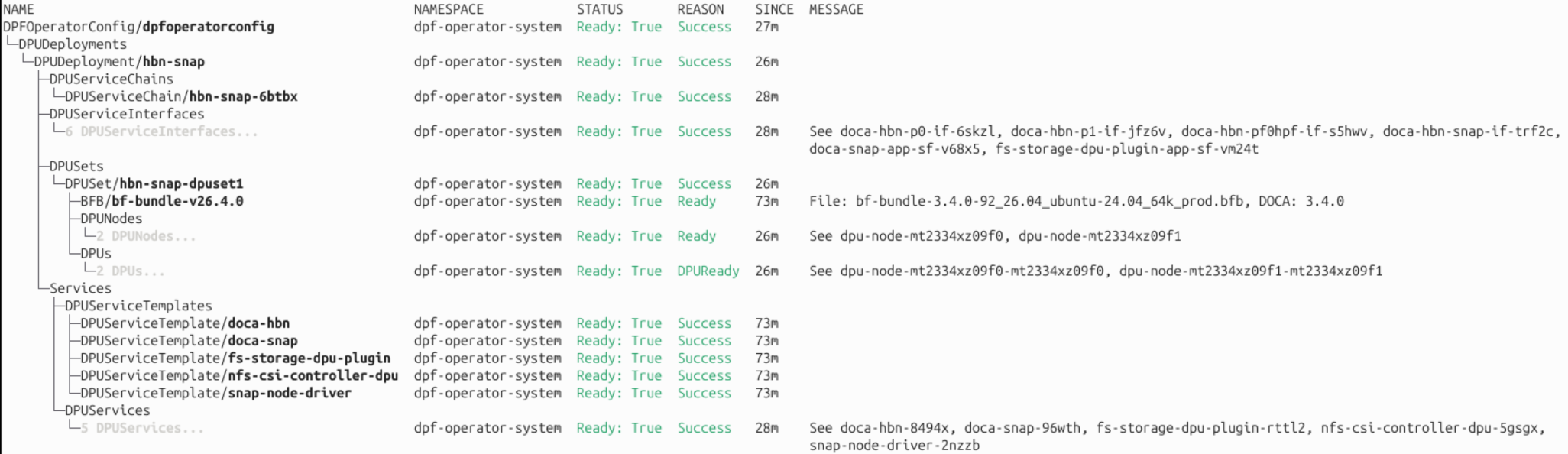
Congratulations, the DPF system with SNAP service has been successfully installed!
To activate the latest BlueField firmware settings, you must reboot all Worker nodes!
Deployment Validation
Test VirtioFS Storage
Several environment variables must be set before running this command.
Create DPUVolume and DPUVolumeAttachment for VirtioFS storage:
cat manifests/05.2-storage-test-virtiofs/*.yaml | envsubst | kubectl apply -f -
This will create the following objects:
DPUVolume for VirtioFS storage
DPUVolumeAttachment for VirtioFS storage
Verify that the DPUVolume resources are in the Ready state:
kubectl wait --for=condition=Ready --namespace dpf-operator-system dpuvolumes --all
dpuvolume.storage.dpu.nvidia.com/test-volume-virtiofs-hotplug-pf-mt2334xz09f0 condition met
dpuvolume.storage.dpu.nvidia.com/test-volume-virtiofs-hotplug-pf-mt2334xz09f1 condition met
Wait for the DPUVolumeAttachments to become Ready:
kubectl wait --for=condition=Ready --namespace dpf-operator-system dpuvolumeattachments --all
dpuvolumeattachment.storage.dpu.nvidia.com/test-volume-attachment-virtiofs-hotplug-pf-mt2334xz09f0 condition met
dpuvolumeattachment.storage.dpu.nvidia.com/test-volume-attachment-virtiofs-hotplug-pf-mt2334xz09f1 condition met
On the host that is used to run this guide, get the VirtioFS tag name of the DPUVolumeAttachment:
kubectl wait --for=condition=Ready dpuvolumeattachments/test-volume-attachment-virtiofs-hotplug-pf-${DPU1_SERIAL} -n dpf-operator-system
kubectl wait --for=condition=Ready dpuvolumeattachments/test-volume-attachment-virtiofs-hotplug-pf-${DPU2_SERIAL} -n dpf-operator-system
tag_1=$(kubectl get -n dpf-operator-system dpuvolumeattachments.storage.dpu.nvidia.com test-volume-attachment-virtiofs-hotplug-pf-${DPU1_SERIAL} -o jsonpath='{.status.dpu.virtioFSAttrs.filesystemTag}')
tag_2=$(kubectl get -n dpf-operator-system dpuvolumeattachments.storage.dpu.nvidia.com test-volume-attachment-virtiofs-hotplug-pf-${DPU2_SERIAL} -o jsonpath='{.status.dpu.virtioFSAttrs.filesystemTag}')
echo "Worker $DPU1_SERIAL VirtioFS tag: $tag_1"
echo "Worker $DPU2_SERIAL VirtioFS tag: $tag_2"

Commands output:
dpuvolumeattachment.storage.dpu.nvidia.com/test-volume-attachment-virtiofs-hotplug-pf-mt2334xz09f0 condition met
dpuvolumeattachment.storage.dpu.nvidia.com/test-volume-attachment-virtiofs-hotplug-pf-mt2334xz09f1 condition met
Worker mt2334xz09f0 VirtioFS tag: 2f2cca6de15d7333tag
Worker mt2334xz09f1 VirtioFS tag: 4ff8f38099083188tag
Connect to the worker nodes with DPUs and set tag variable to point to the VirtioFS tag retrieved in the previous step.
For Worker1:

$ ssh worker1
depuser@worker1:~$ sudo mkdir /mnt/virtio
depuser@worker1:~$ sudo mount -t virtiofs 2f2cca6de15d7333tag /mnt/virtio

depuser@worker1:~$ mount | grep virtio
2f2cca6de15d7333tag on /mnt/virtio type virtiofs (rw,relatime)

depuser@worker1:~$ cd /mnt/virtio/
Repeat the same steps for Worker2 with tag - 4ff8f38099083188tag.
FIO performance test
-
Connect to one of the Worker nodes
-
Install fio package:
Ubuntu 24.04: sudo apt-get install -y fio -
Create FIO job file:
cat /mnt/virtio/job-4k.fio [global] ioengine=libaio direct=1 iodepth=32 rw=read bs=4k size=10G numjobs=8 runtime=60 time_based group_reporting [job1] filename=/mnt/virtio/test.fio -
Run FIO job file:
sudo fio /mnt/virtio/job-4k.fio

job1: (g=0): rw=read, bs=(R) 4096B-4096B, (W) 4096B-4096B, (T) 4096B-4096B, ioengine=libaio, iodepth=32
...
fio-3.36
Starting 8 processes
job1: Laying out IO file (1 file / 10240MiB)
Jobs: 8 (f=8): [R(8)][100.0%][r=613MiB/s][r=157k IOPS][eta 00m:00s]
job1: (groupid=0, jobs=8): err= 0: pid=2418: Tue Jul 14 11:23:11 2026
  read: IOPS=146k, BW=571MiB/s (599MB/s)(33.5GiB/60006msec)
    slat (nsec): min=1980, max=824089, avg=11242.80, stdev=16173.33
    clat (usec): min=72, max=105186, avg=1739.39, stdev=5219.00
     lat (usec): min=254, max=105191, avg=1750.63, stdev=5217.56
    clat percentiles (usec):
     |  1.00th=[  351],  5.00th=[  383], 10.00th=[  396], 20.00th=[  412],
     | 30.00th=[  424], 40.00th=[  437], 50.00th=[  445], 60.00th=[  453],
     | 70.00th=[  469], 80.00th=[  490], 90.00th=[  537], 95.00th=[16581],
     | 99.00th=[25297], 99.50th=[28443], 99.90th=[41157], 99.95th=[45351],
     | 99.99th=[55313]
   bw (  KiB/s): min=508056, max=664344, per=99.97%, avg=584530.49, stdev=4175.65, samples=952
   iops        : min=127014, max=166086, avg=146132.61, stdev=1043.91, samples=952
  lat (usec)   : 100=0.01%, 250=0.01%, 500=83.41%, 750=10.15%, 1000=0.11%
  lat (msec)   : 2=0.05%, 4=0.01%, 10=0.01%, 20=2.97%, 50=3.26%
  lat (msec)   : 100=0.02%, 250=0.01%
  cpu          : usr=2.50%, sys=25.25%, ctx=7640608, majf=0, minf=798
  IO depths    : 1=0.1%, 2=0.1%, 4=0.1%, 8=0.1%, 16=0.1%, 32=100.0%, >=64=0.0%
     submit    : 0=0.0%, 4=100.0%, 8=0.0%, 16=0.0%, 32=0.0%, 64=0.0%, >=64=0.0%
     complete  : 0=0.0%, 4=100.0%, 8=0.0%, 16=0.0%, 32=0.1%, 64=0.0%, >=64=0.0%
     issued rwts: total=8771722,0,0,0 short=0,0,0,0 dropped=0,0,0,0
     latency   : target=0, window=0, percentile=100.00%, depth=32

Run status group 0 (all jobs):
   READ: bw=571MiB/s (599MB/s), 571MiB/s-571MiB/s (599MB/s-599MB/s), io=33.5GiB (35.9GB), run=60006-60006msec
The performance results listed in this document are indicative and should not be considered as formal performance targets for NVIDIA products.
Done.
Authors
|
|
Vitaliy Razinkov Vitaliy Razinkov is a Solutions Architect on the NVIDIA Networking team, specializing in complex Kubernetes, OpenShift, and Microsoft solutions. With over 25 years of experience in senior technical roles, he brings deep expertise in designing and implementing advanced infrastructures. Vitaliy has authored several reference design guides on Microsoft technologies, RoCE/RDMA-accelerated machine learning in Kubernetes/OpenShift, and containerized solutions—all available on the NVIDIA Networking Documentation site. |

Last updated: