The SFP28 pin assignment is SFF-8419 compliant.
SFP28 Function Definition
|
Pin |
Connector Pin Name |
Port A Signal Name |
|
1 |
VeeT |
Module Transmitter Ground |
|
2 |
Tx_Fault |
Module Transmitter Fault |
|
3 |
Tx_Disable |
Transmitter Disable. Turns off transmitter laser output |
|
4 |
SDA |
2-wire Serial Interface Data Line |
|
5 |
SCL |
2-wire Serial Interface Clock |
|
6 |
Mod_ABS |
Module Absent. Grounded within the module |
|
7 |
RS0 |
Rate Select 0, optionally controls SFP+ module receiver |
|
8 |
Rx_LOS |
Receiver Loss of Signal Indication |
|
9 |
RS1 |
Rate Select 1, optionally controls SFP+ module transmitter |
|
10 |
VeeR |
Module Receiver Ground |
|
11 |
VeeR |
Module Receiver Ground |
|
12 |
RD- |
Receiver Inverted Data Output |
|
13 |
RD+ |
Receiver Non-Inverted Data Output |
|
14 |
VeeR |
Module Receiver Ground |
|
15 |
VccR |
Module Receiver Power Supply |
|
16 |
VccT |
Module Transmitter Power Supply |
|
17 |
VeeT |
Module Transmitter Ground |
|
18 |
TD+ |
Transmitter Non-Inverted Data Input. AC coupled |
|
19 |
TD- |
Transmitter Inverted Data Input. AC coupled |
|
20 |
VeeT |
Module Transmitter Ground |
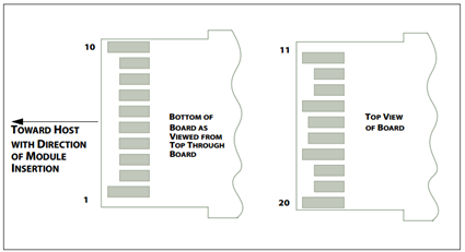
SFP28 Module Pad Layout
Digital Diagnostic Monitoring Features
The transceiver’s management functions comply with SFF-8472.
-
Physical layer link tuningTx/Rx CDR control, refer to Appendix
-
DDM – Readout and Warning/Alarm IndicationRx receive optical power monitorTx transmit optical power monitorTx bias current monitorModule supply voltage monitorModule case temperature monitor
-
MSA supported features and interrupt indicationsTx & Rx LOSTx & Rx LoLTx faultTx & Rx disable
Last updated: