The following instructions describe how to install the OCP 21” adapter tray, and how to mount the SN5600D switch system in the adapter tray.
Safety & Prerequisites
Rack Preparation:
-
Ensure the OCP rack is properly leveled and secured to the floor according to the site's standards.
-
The rack must be equipped with L-shaped support brackets at the target installation height.
Heavy Equipment: Always use a server lift or two people when handling the switch and the adapter tray.
Required Components:
|
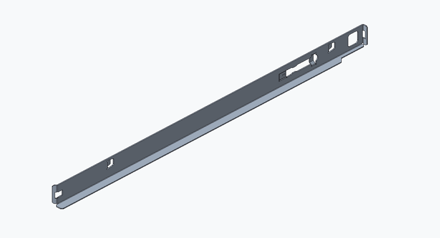
2 x L‑shaped support brackets (left and right) |
|
|
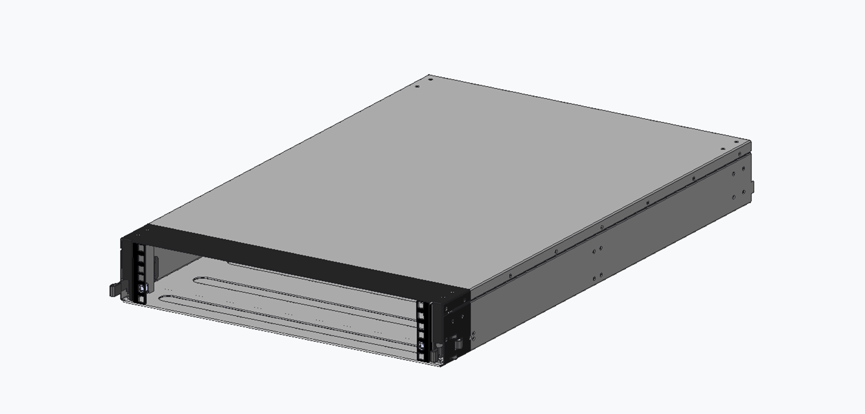
1 x Adapter tray |
|
|
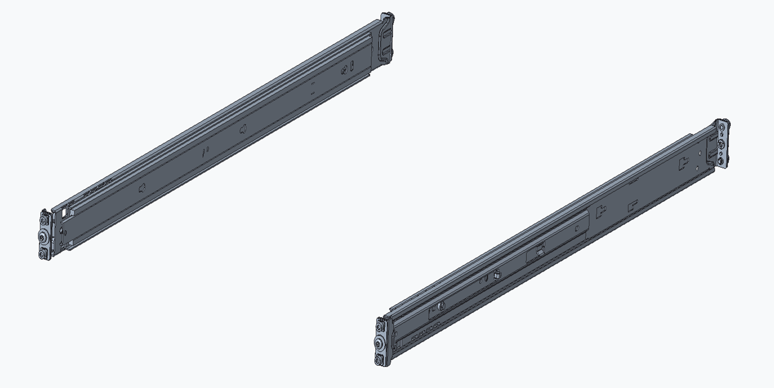
1 x SN5600D Switch Rail-kit |
|
|
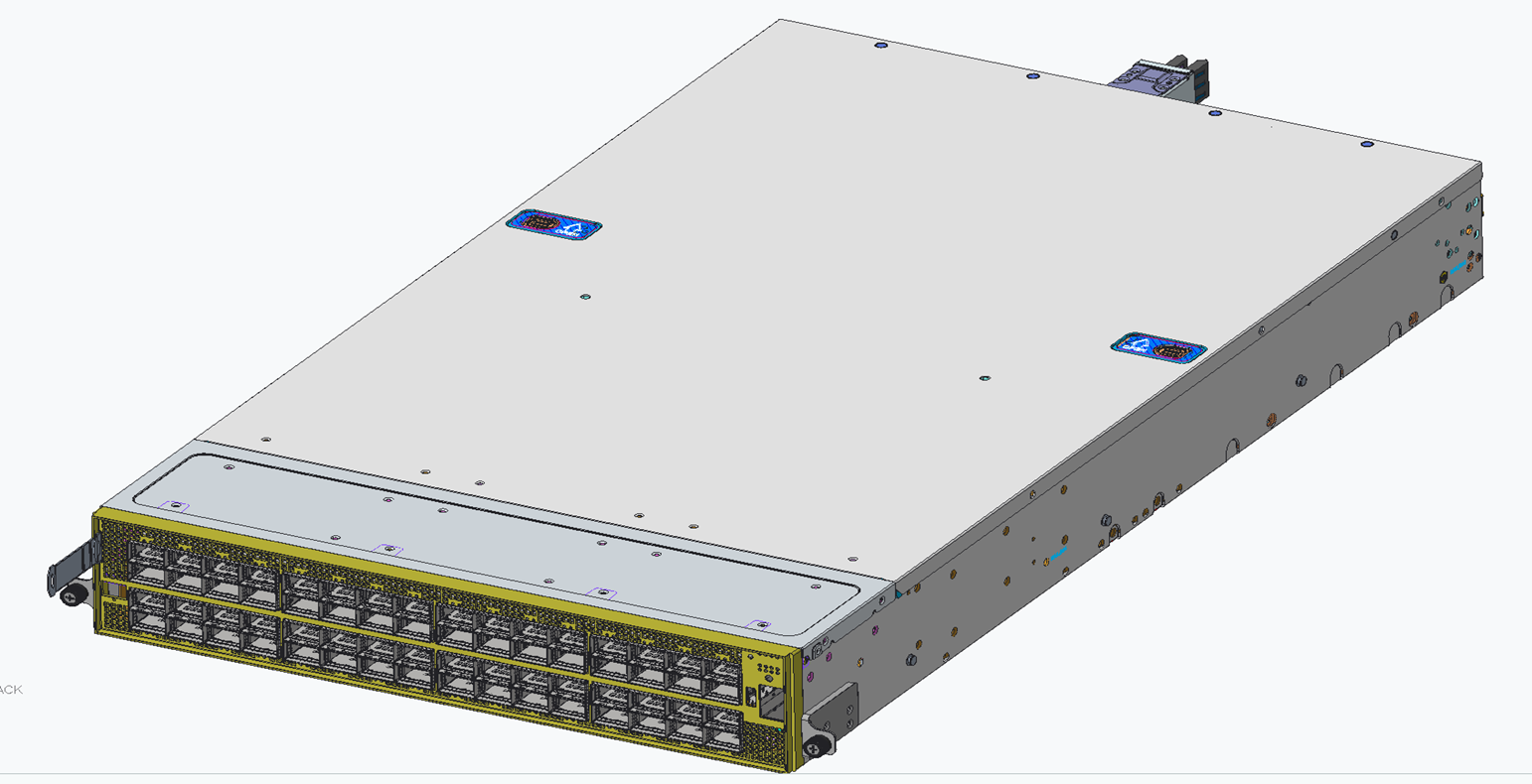
1 x SN5600D Switch system |
|
Installation Process
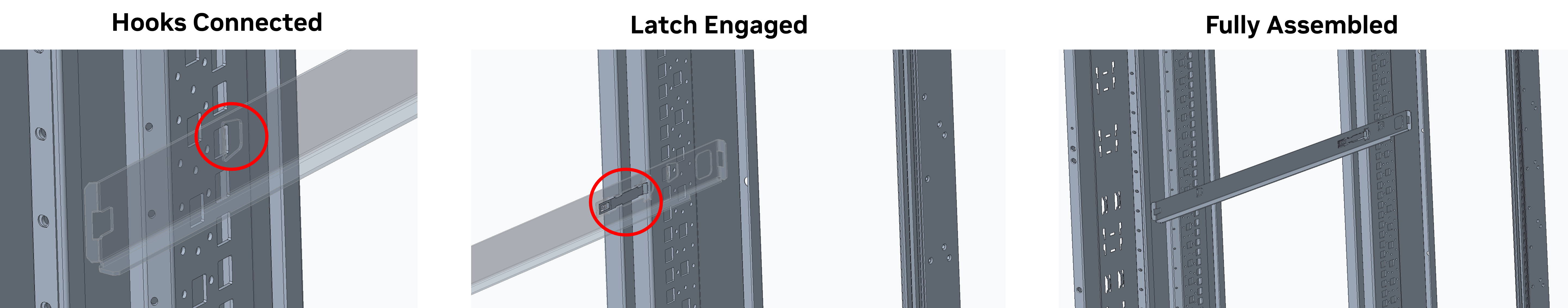
Step 1: Installing the L-Shaped Brackets into the OCP Rack
-
-
Define the height: Select the desired OU height within the 21" OCP rack.
-
Mount the Brackets: Align the brackets with the rack's pre-punched holes.
-
Engagement: Angle the rail in to seat the hooks into the corresponding locations. Make sure that the latch side of the brackets faces the rear of the rack.
-
Verification: Confirm that the latches are fully engaged and there is no interference with other rack parts.
-
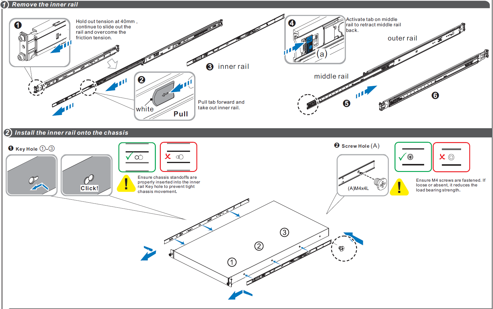
Step 2: Install the Rail-Kit onto the Adapter Tray
-
-
Install the standard 19" Rail-Kit onto the adapter tray's front and rear EIA posts.
-
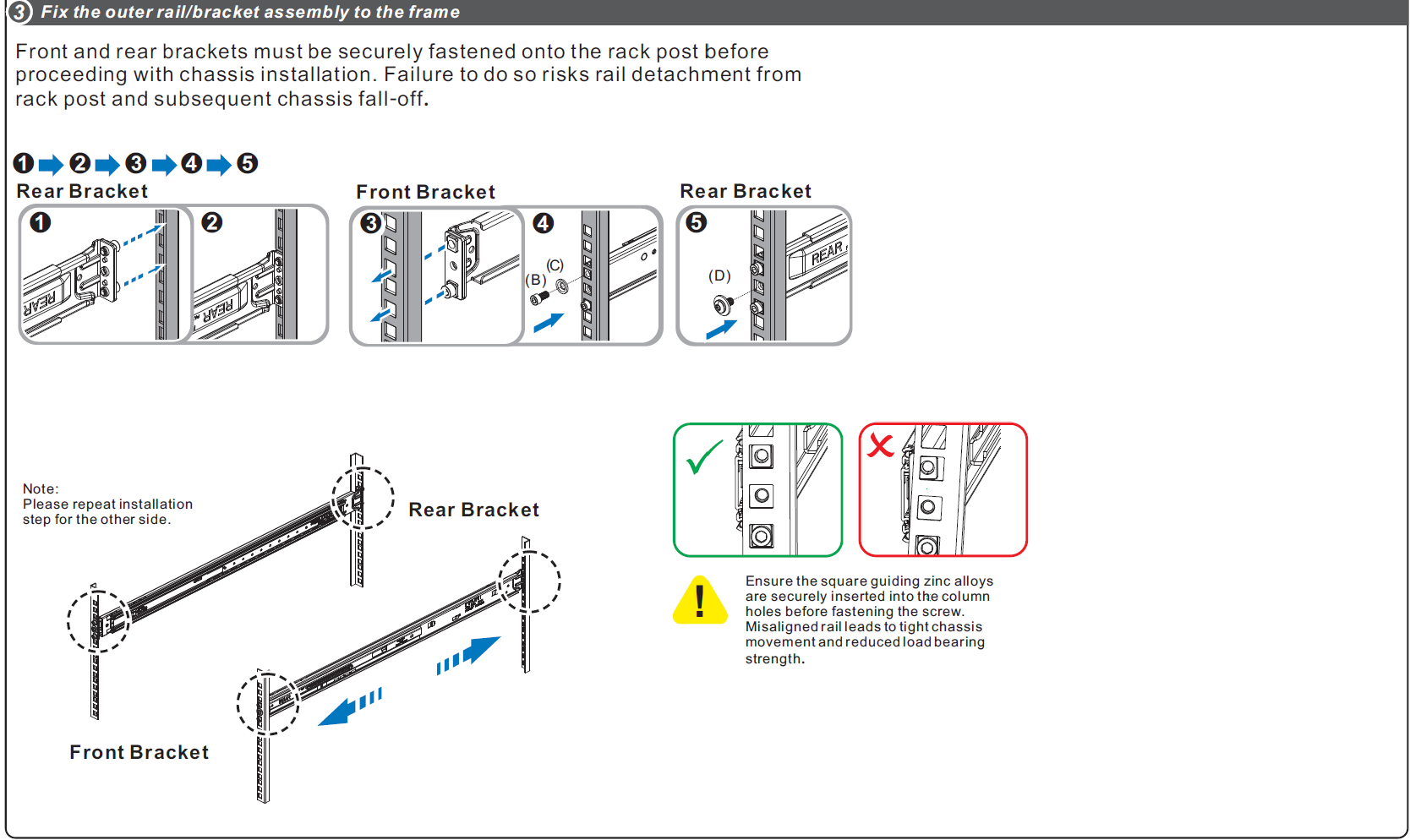
Follow assembly steps 1-3, as detailed in the SN5600D Rail-Kit Section:
-
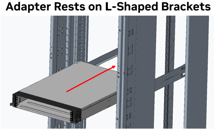
Step 3: Mount the Adapter Tray into the OCP Rack
-
-
Select the RU position
-
Choose the 2U window (e.g, RU 20-21) where the switch system will be located, and confirm that the L‑shape support brackets (or shelf rails) are installed at that height.
-
-
Placement: Rest the bottom flanges of the adapter tray onto the two L-shaped support brackets previously installed in the rack.
-
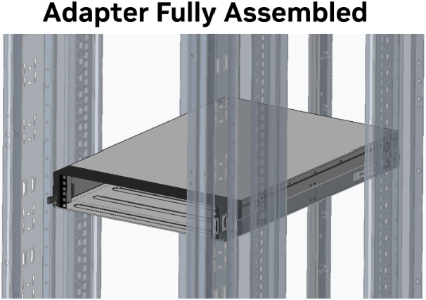
Securing: Slide the tray along the brackets until it latches securely into position.
-
Final Checks:
-
-
-
Ensure that the tray is correctly seated and does not obstruct doors or busbars.
-
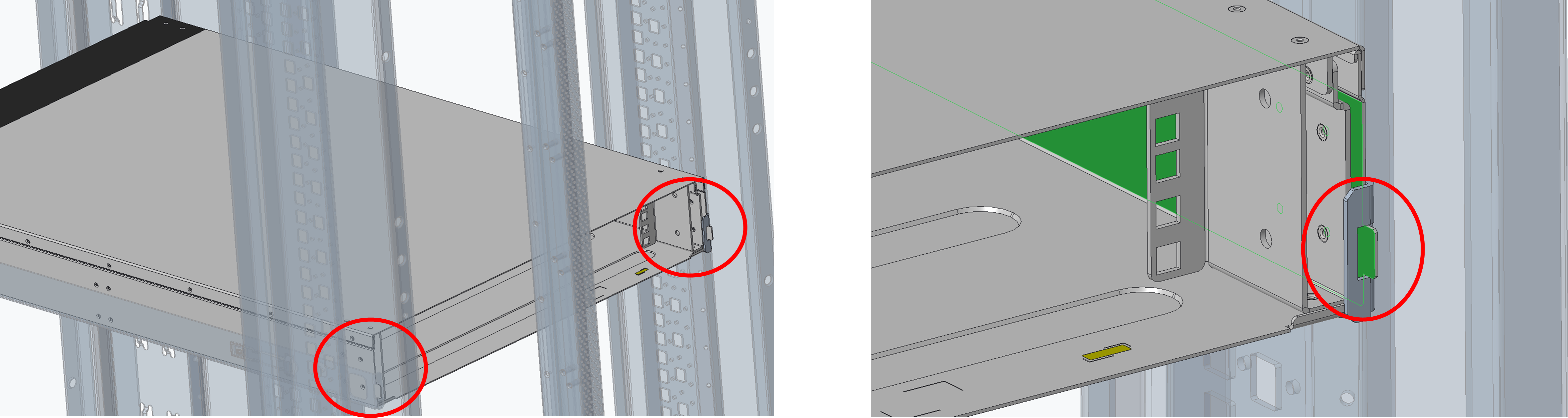
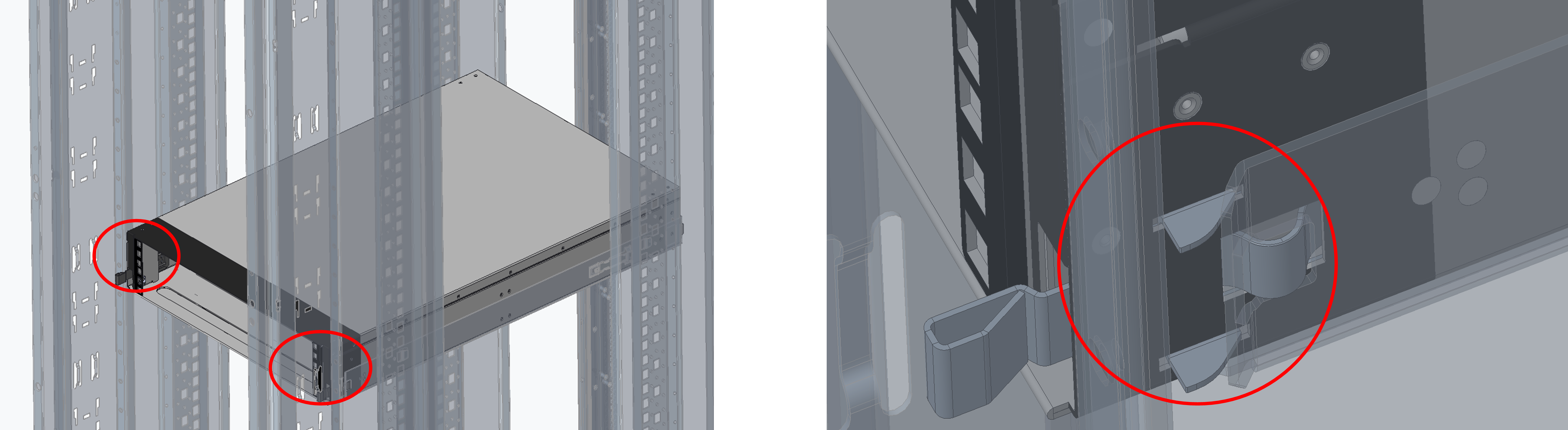
Verify the tray's rear extenders are properly inserted into the rear flanges of the L-shaped brackets on both sides.
-
Confirm that the front hooks of the adapter tray are latched to the rack's front posts.
-
-
Step 4: Assemble the Switch Rail-Kit
Follow assembly step 4, as detailed in the SN5600D Rail-Kit Section:
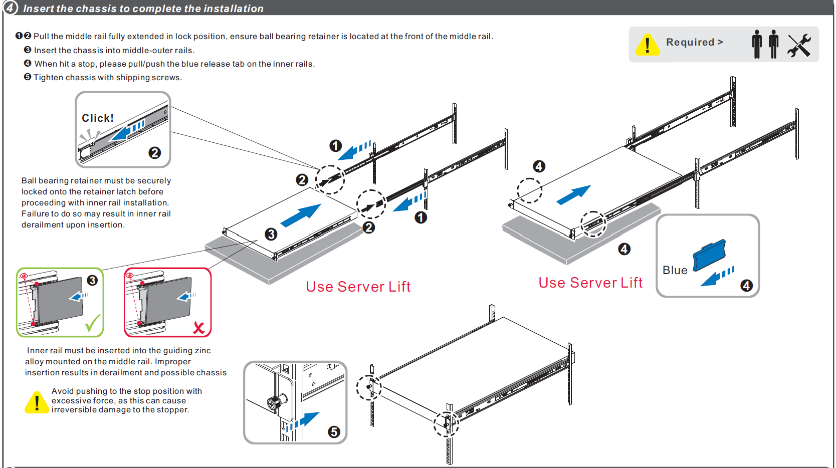
Make sure to secure the chassis in the rack by tightening the designated screws.
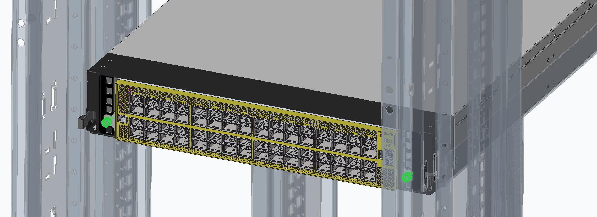
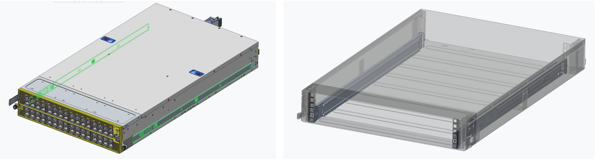
Step 5: Install the Switch System in the Adapter Tray
-
-
Using the pre-installed rail-kit, slide the switch system into the adapter tray until it is fully engaged.
-
Secure the chassis by tightening the designated screws.
-
Perform a final inspection of both the front and rear of the rack to ensure the system is properly seated and the busbar connection is fully plugged.
-
Last updated: