
Networking NVIDIA Spectrum-6 SN6000 Switch Systems Hardware User Manual

SN6600-LD/SN6810-LD Rail Kit

The SN6600-LD and SN6810-LD systems are compatible with NVIDIA MGX v1.2 racks.

Kit Part Number

Description 

930-9SKIT-00L0-00F

Installation kit for standard 2U switches in MGX v1.2 racks

The following instructions have been prepared and provided with permission from King Slide.

Package Contents 

image-2025-3-16_16-53-1.png

Installation Instructions

Description

Illustration

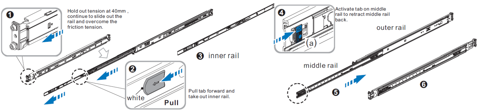
  1. Remove the inner rail.

image-20260914-114812.png


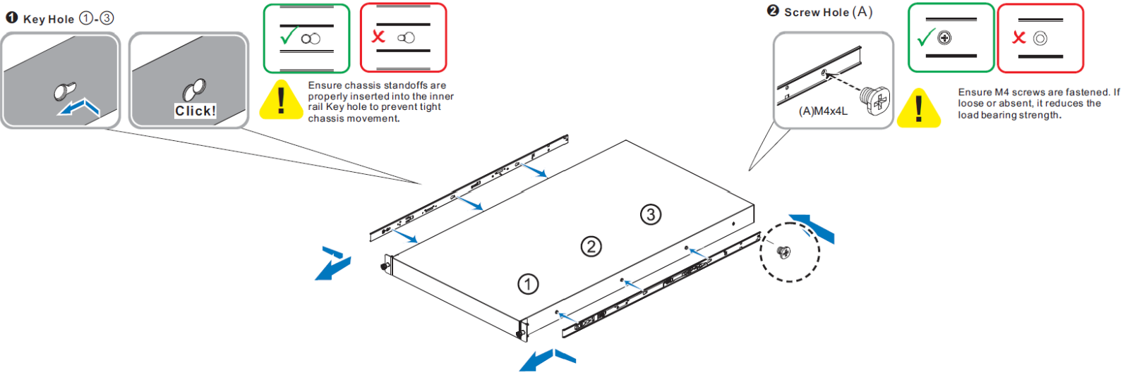
  1. Install the inner rail onto the chassis.

image-20260914-114911.png
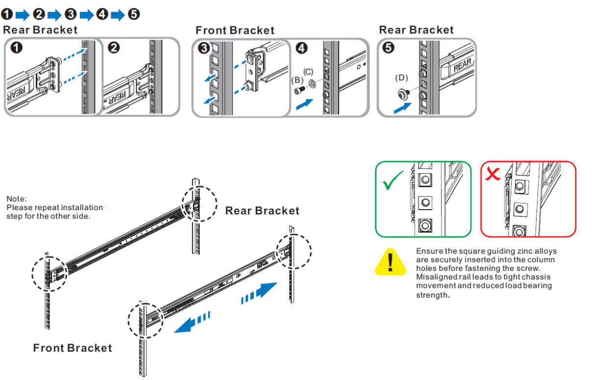
  1. Fix the outer rail bracket/assembly to the frame.

    The front and rear brackets mus be securely fastened on the rack post before proceeding with chassis installation. Failure to do so risks rail detachment from rack post and subsequent chassis fall-off.

image-20260914-115106.png


  1. Attach the DGX ejector bars to the rack posts:

    a. Insert four M5 cage nuts in the desired slots of the rack above the rear brackets. 

    Make sure to secure the nuts in the correct location within the 2U enclosure, as shown in the below illustration.

    b. Attach the left and right ejector bars to the rack by screwing two screws in each bar. Tighten the screws to secure the ejector bars in the rack's posts, applying a torque of 2.0 +/-0.1 Nm.

Make sure the ejector bars do not protrude over the rack posts

CRITICAL ORIENTATION REQUIREMENT

The switch must be mounted in an upright position. Verify the correct orientation before inserting the unit into the rack rails.
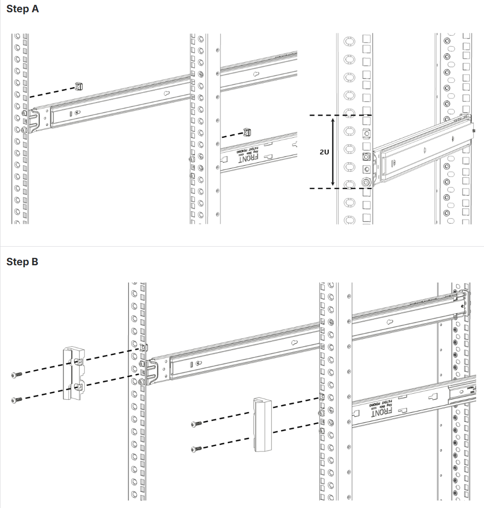

image-20260914-115151.png


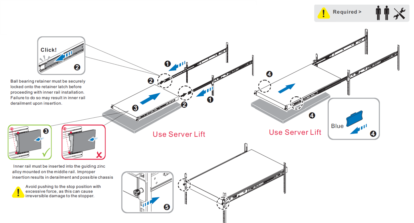
  1. Insert the chassis to complete the installation:

    a. Pull the middle rail fully extended in lock position, ensure ball bearing retainer is located at the front of the middle rail.
    b. Insert the chassis into middle-outer rails.
    c. When hit a stop, please pull/push the blue release tab on the inner rails.
    d. Tighten chassis with shipping screws.

image-20260914-115513.png


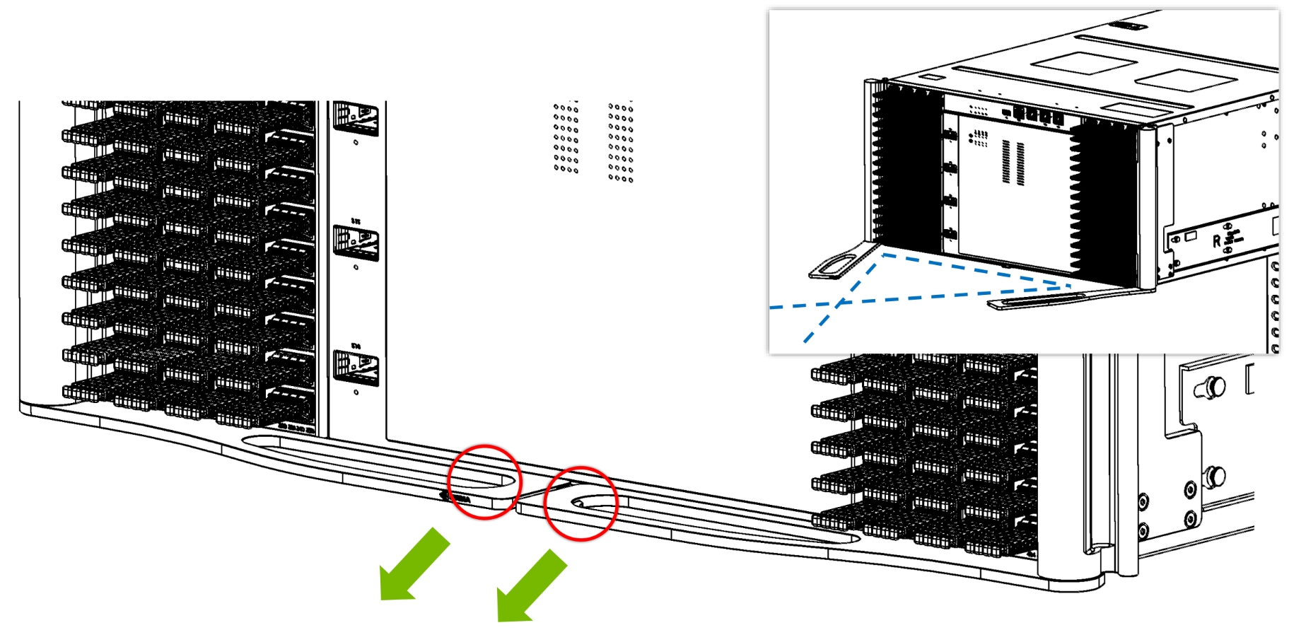
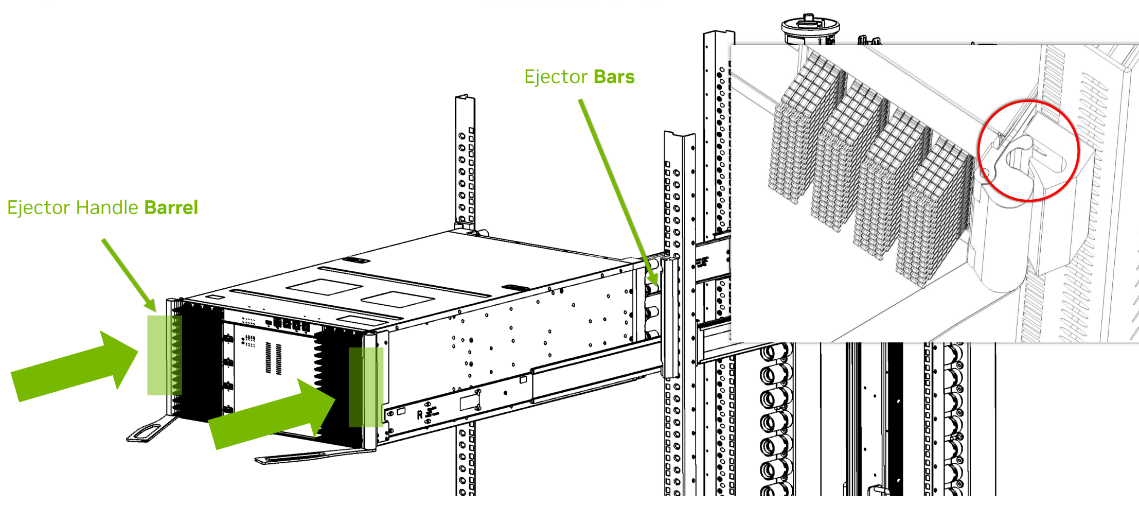
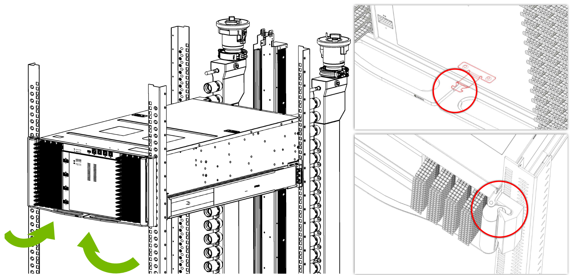
  1. Push on the latches to release the handles
    a. Fully open the handles.
    b. Push the system in by the handle barrels (indicated in green) until the barrels meet the bars on the system post.
    c. Use the handles to push the system the remaining distance and lock it onto the hook as illustrated below.
    d. Ensure the barrels are fully engaged with the bars.

image-20260907-092248.png
image-20260907-092401.png
image-20260907-093228.png

Disassembly Instructions

Description

Illustration

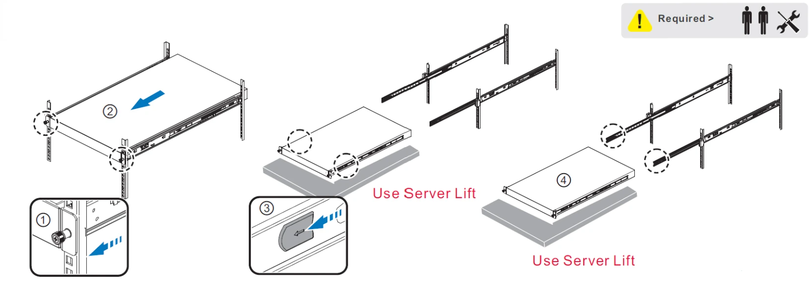
  1. Remove the chassis in a limited space -

① ② Loosen the shipping screws, then rotate and pull the cantilever handle to unlatch and pull out the chassis.

③ ④ Once fully extended into the locked-out position, pull the disconnect tab forward to remove the chassis.

image-20260915-102008.png


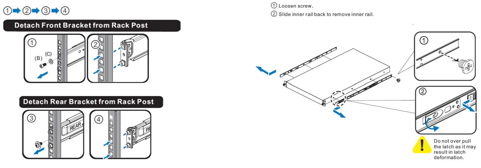
  1. Detach the front / rear brackets from the rack posts.

image-20260915-102149.png

Troubleshooting

Description

Illustration

Failure Mode: Chassis falling off or tilting after installation

image-20260915-102429.png
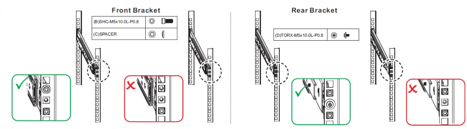
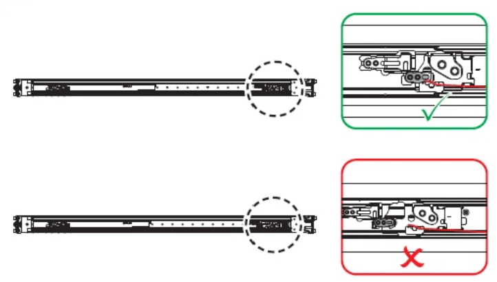
  • Cause 1: The operator installed the unit without fastening the screws on the front and rear brackets, or the screws were fastened loosely, causing them to detach.

  • Solution: Ensure the correct screws are selected and securely tightened.

image-20260915-102541.png
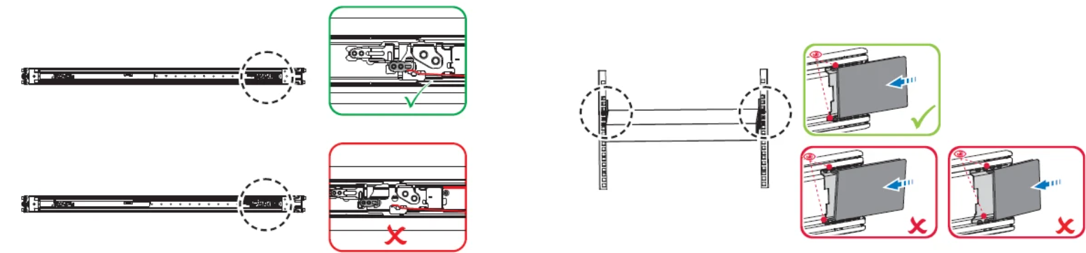
  • Cause 2: The inner rail derailed from the middle rail during installation. This is likely because the ball bearing retainer was not locked by the retainer latch during inner rail installation, or the inner rail was not properly inserted into the guiding zinc alloy mounted on the middle rail.

  • Solution: Ensure the ball bearing retainer is securely locked onto the retainer latch before installing the chassis or inner rail. Additionally, verify that the inner rail is properly aligned with and slotted into the guiding zinc alloy during installation.

image-20260915-102631.png
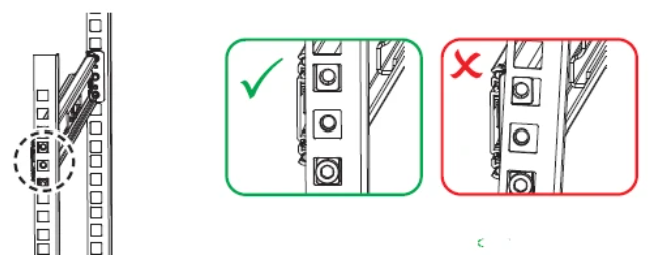
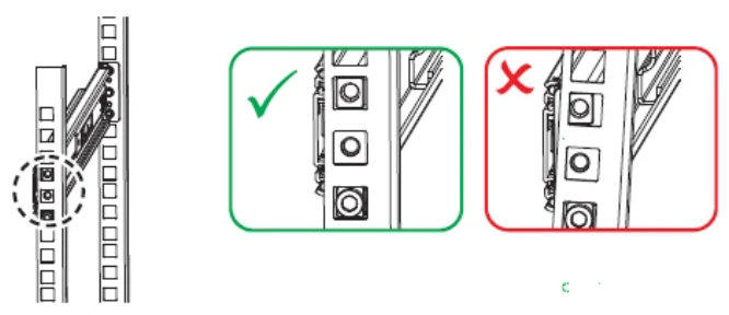
  • Cause 3: The square guide on the front bracket was improperly inserted into the rack column holes.

  • Solution: Ensure the square guide block on the front bracket is fully inserted into the column holes before tightening the screw.

image-20260915-102844.png

Failure Mode: Stiff or tight chassis movement

  • Cause 1: Chassis standoffs were incorrectly slotted into the keyholes, resulting in a distorted rail profile.

  • Solution: Ensure all standoffs are properly aligned and inserted into their corresponding keyholes.


image-20260915-102944.png
  • Cause 2: The ball bearing retainer was not locked onto the retainer latch during inner rail insertion, causing the inner rail to detach from the ball bearing retainer.

  • Solution: Ensure the ball bearing retainer is securely locked onto the retainer latch before inserting the inner rail.


image-20260915-111215.png


Failure Mode: Insufficient or abnormal load-bearing strength

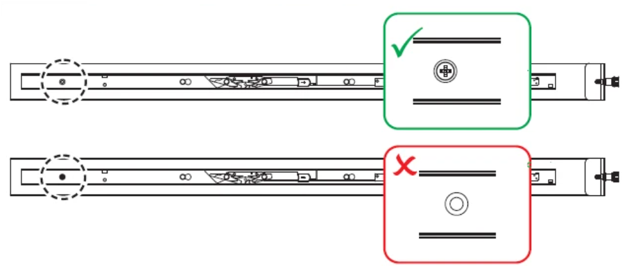
  • Cause 1: The inner rail was attached to the chassis without securing the screws.

  • Solution: Ensure the M4 screws are securely fastened.

image-20260915-111304.png


  • Cause 2: The square guide on the front bracket was incorrectly inserted into the rack column holes.

  • Solution: Ensure the square guide block on the front bracket is fully inserted into the column holes before tightening the screw.

image-20260915-111328.png


Last updated: