Overview
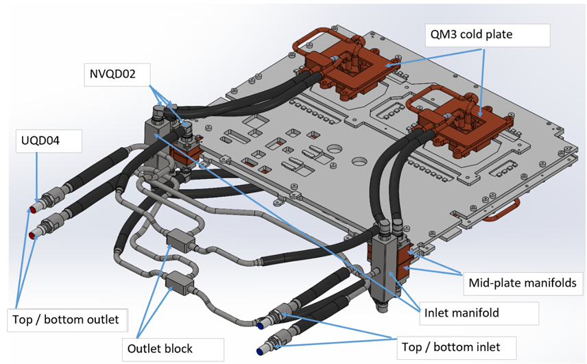
The Q3450-LD liquid-cooling system features two parallel cooling loops operating concurrently. Liquid enters via two separate inlet ports and exits through two outlet ports. Fluid enters through two inlet manifolds on the left and right sides of the system's rear part, each splitting into two paths: one to the upper QM3 cold plate (left/right) and one to the lower QM3 cold plate (left/right), forming two parallel loops. After cooling the QM3 cold plates, the fluid flows to the mid-plate manifolds, then cools the switch board components via upper and lower loops (left/right). Unlike the inlet lines, which are split by side (left/right), the outlet lines are grouped by level: upper sections from both sides converge at the top outlet block, and lower sections at the bottom outlet block. The combined flow exits through ports on the left side.
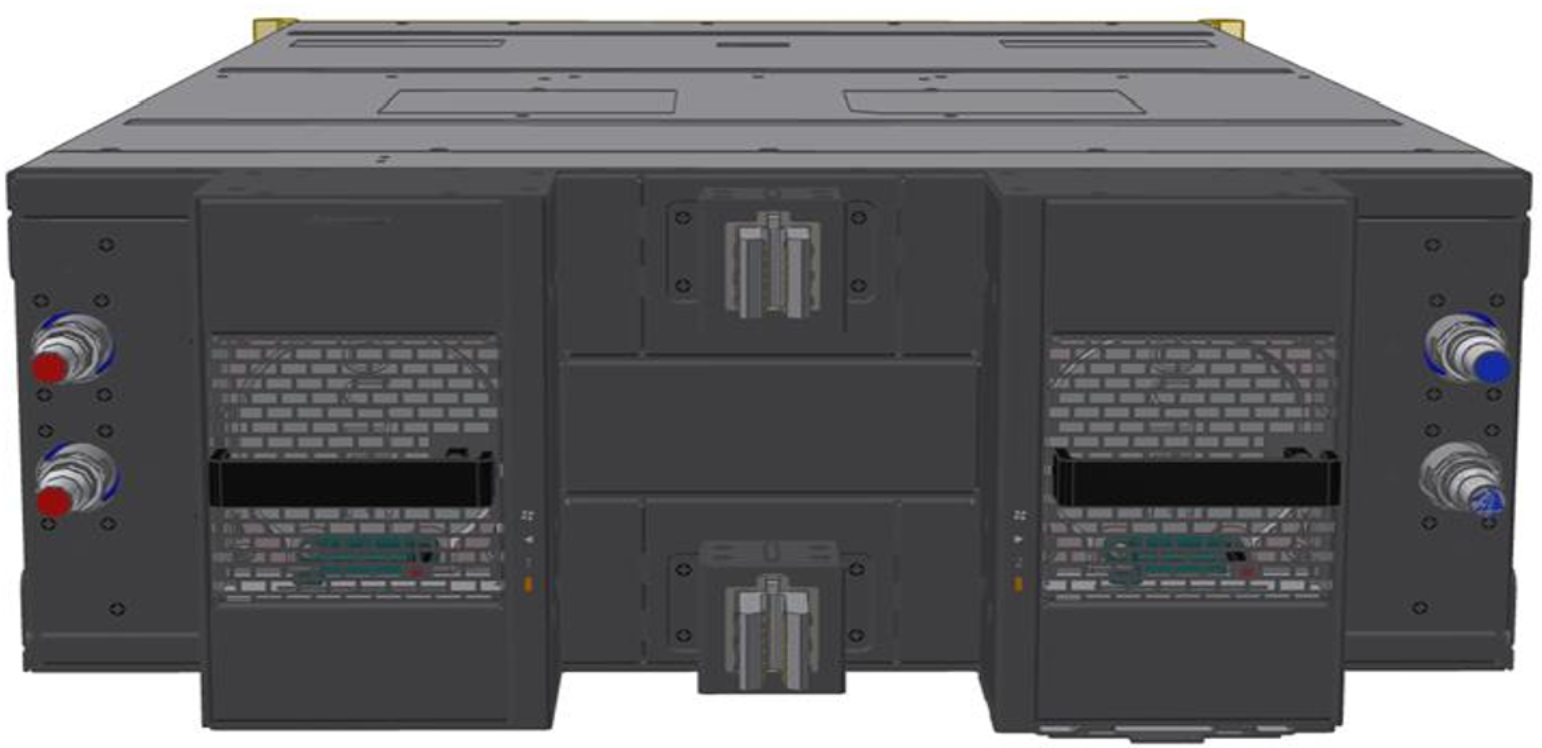
Liquid-Cooling System 3D View
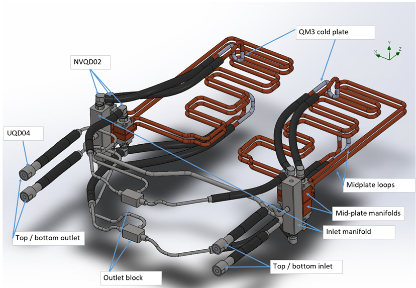
Liquid-Cooling System 3D View with Visible Mid-Plate Loops
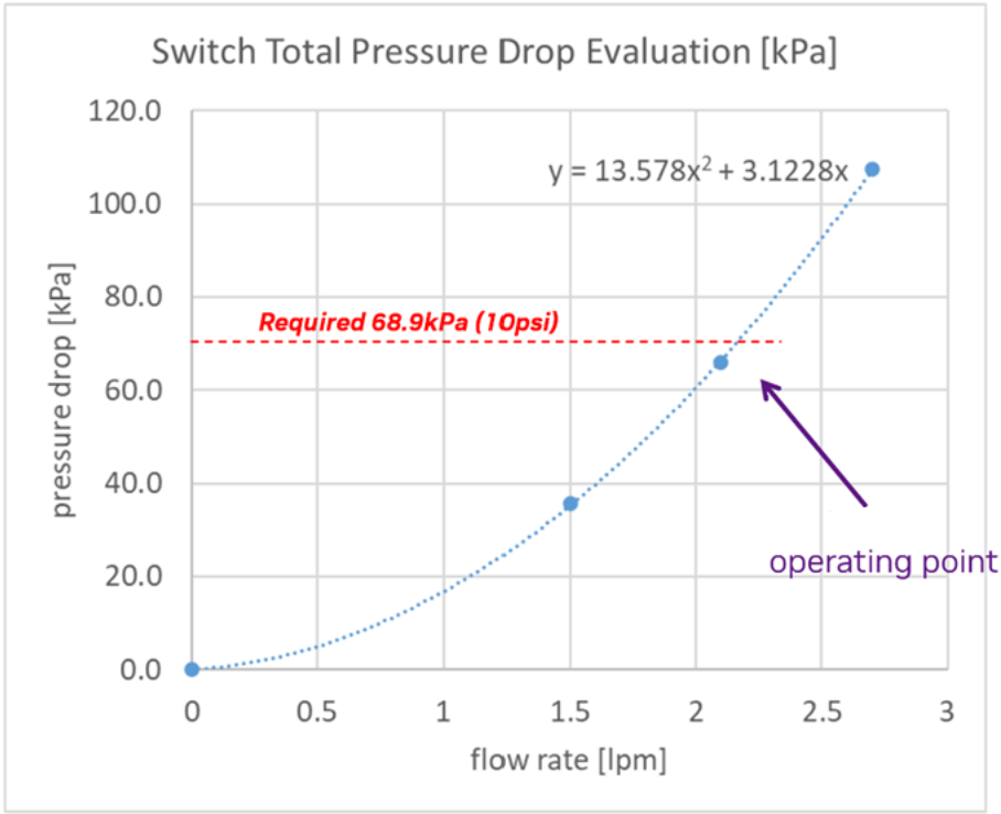
The system operates at [4.3 LPM, 10 PSI]. The below curve applies to PG25 at 45°C (see Specifications). As the system has two parallel inlet/outlet ports, the flow rate at the operating condition is half the total switch liquid flow rate.
|
Liquid Cooling System P-Q Curve |
|
Deployment
Inserting the Switch Module (Liquid System Related)
The switch modules are pre-filled with nitrogen in the cooling system, pressurized to at least 1 psi. If the pressure is below 1 psi, perform a "Pressure Hold": refill to 50 psi with N2, wait 12 hours, and verify that the pressure remains above 48 psi to pass. Positive nitrogen pressure prevents humidity or dust ingress.
-
Before insertion, release the gas using the open-ended hose from the maintenance kit.
-
Connect the hose to either of the two FRU hoses to automatically expel the gas.
-
Disconnect the hose once the gas is fully released, then proceed with module insertion.
Failure to fully flood the cooling system with liquid before powering-on may cause significant damage and void the warranty.
Liquid-Cooling System Related Actions
Pressure Check of Nitrogen-Filled Components
Purpose:
-
Confirm that cold plate assemblies, switch trays, and manifolds retain supplier-filled N2 pressure, ensuring no leaks during transit.
Required Hardware:
-
Digital pressure gauge (0–2.1 bar or 0–3.4 bar), data logging.
Process
-
Scan the QR code, log pressure
-
Release the internal pressure
-
Cycle time: <1 minute
Pass/Fail Criteria
-
Must retain ≥1 psi.
-
If the pressure is lower than 1 psi, please perform a "Pressure Hold" test as follows:
-
Refill to 50 psi with N2
-
Wait 12 hours
-
Recheck the pressure. If the pressure is above 48 psi, the unit has passed the test.
-
-
Failures are returned to the supplier.
PG25 Fill
Purpose:
-
To fill assemblies (both individual components and full racks) with 25% propylene glycol, and 75% water solution, ensuring complete fluid coverage and air removal for optimal thermal performance.
Required Hardware:
-
For vacuum fill: Vacuum pump, liquid trap
-
For positive pressure fill: Fill pump
-
25-micron filter on the supply side (for both the component and the rack)
Process
-
Vacuum Fill:
-
Pull vacuum on the assembly from the outlet quick disconnect (QD).
-
Fill the fluid from the inlet QD.
-
Stop filling when the fluid enters the liquid trap.
-
Vacuum specification: 5 kPa or less.
-
-
Positive Pressure Fill:
-
Use a fill pump to introduce coolant.
-
Circulate the fluid back into the reservoir briefly to ensure no bubbles remain.
-
Pass/Fail Criteria
-
Fluid reservoir weight can optionally be measured before and after filling as a quality check.
Caveats:
-
If using a positive pressure pump with circulation, ensure a 25-micron filter is installed on the supply side.
-
If the assembly is complex with multiple fluidic elevations or high points, vacuum filling is preferred.
-
Expected Cycle Time: 2–3 minutes.
RMA
|
Temperature Sensitivity of Fully Filled Liquid Systems |
TPU Exposure Risks |
Recommended Shipment Processes |
Storage Time Limitation |
|---|---|---|---|
|
Fully filled liquid cooling systems are susceptible to temperature fluctuations during transportation or storage, potentially causing volume changes and deformation damage. |
Prolonged storage of fully filled PG25 liquid systems can damage TPU internal LC connections. To prevent this, specific shipment processes must be followed. |
Partial Drainage Shipment
Alternate Wet Tray Shipment
|
Regardless of the chosen shipment method, limit storage time to a maximum of 45 days before arrival at NVIDIA RMA Labs. |
|
RMA with Liquid-Drained System For drained systems, ensure the shipping temperature remains between -40 °C and +70 °C. 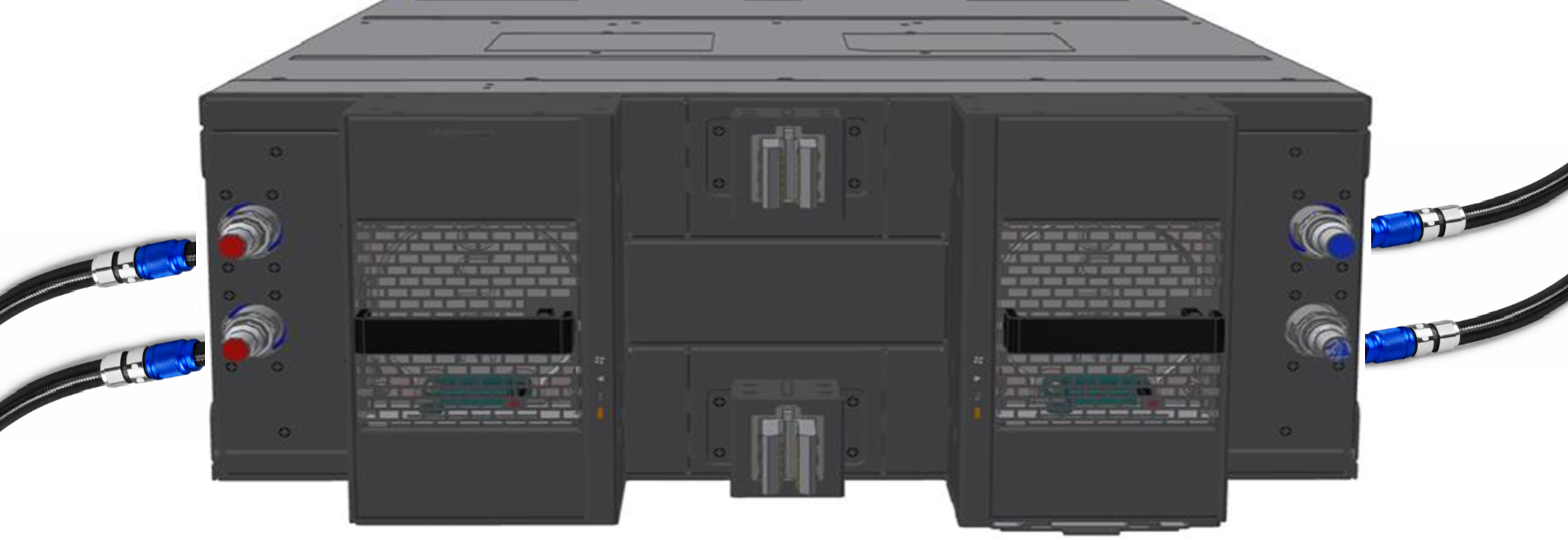
|
|
RMA with Liquid-Filled System Connect a hose between the ports. Ensure the shipping temperature remains between 5 °C and 60 °C. 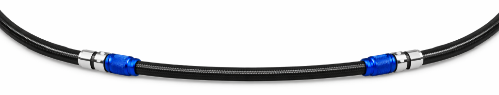
|
Specifications
|
Parameter |
Value |
|---|---|
|
Minimal liquid inlet temperature |
17 °C |
|
Maximal liquid inlet temperature |
45 °C |
|
Maximal liquid return temperature |
55 °C |
|
Target sustained system flow rate |
4.3 l/min |
|
Normal pressure |
2.4 Bar |
|
Max operating/shipment pressure (gauge) abnormal / single fault |
5 Bar |
|
Burst pressure (gauge) |
15 Bar |
|
Liquid pressure drop |
10 PSI |
|
Coolant |
Recochem OAT PG25 |
|
Connection type |
Tray side (male): UQD04 Rack manifold (female) side: BUQD04 |
|
Filtration Requirement |
Support [25um: 50um] |
|
Liquid volume |
410 mL |
|
Ambient Temperature |
Operational: 5°C to 40°C for altitude: 0-900 m Above 900 m, derate 1 °C / 175 m (do not install unit above 3,050 m in any case).
|
|
Humidity |
Operational: 10-85% non-condensing
|
|
Altitude |
Operational: 0-3,050 meters Non-operational: 0-12,000 m |
Last updated: