System Installation and Initialization
Installation and initialization of the system require attention to the normal mechanical, power, and thermal precautions for rack-mounted equipment.
The rack mounting holes conform to the EIA-310 standard for 19-inch racks. Take precautions to guarantee proper ventilation in order to maintain good airflow at ambient temperature.
Due to thermal considerations, the switch systems must be installed in a horizontal position. do not install the systems vertically.
|
Incorrect |
Correct |
|---|---|
|
|
|
-
Unless otherwise specified, NVIDIA products are designed to work in an environmentally controlled data center with low levels of gaseous and dust (particulate) contamination.
-
The operation environment should meet severity level G1 as per ISA 71.04 for gaseous contamination and ISO 14644-1 class 8 for cleanliness level.
The installation procedure for the system involves the following phases:
|
Step |
Procedure |
See |
|---|---|---|
|
1 |
Follow the safety warnings |
Safety Warnings |
|
2 |
Pay attention to the air flow consideration within the system and rack |
Air Flow |
|
3 |
Make sure that none of the package contents is missing or damaged |
Package Contents |
|
4 |
Mount the system into a rack enclosure |
19" System Mounting Options |
|
5 |
Power on the system |
|
|
6 |
Perform system bring-up |
System Bring-Up of Managed Systems |
|
7 |
[Optional] FRU replacements |
FRU Replacements |
Safety Warnings
Prior to the installation, please review the Safety Warnings. Note that some warnings may not apply to all models.
Air Flow
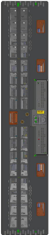
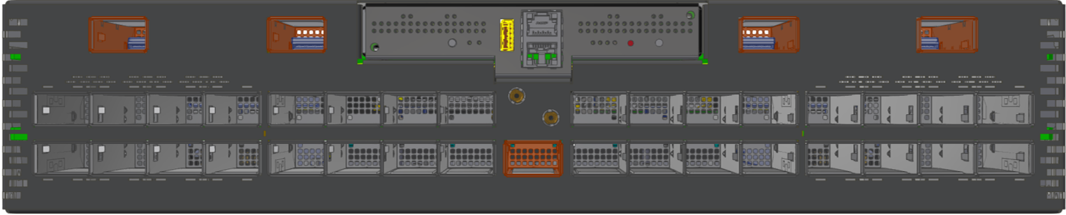
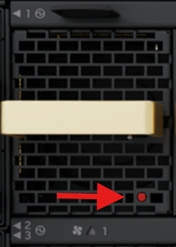
Currently, the NVIDIA XDR systems are offered with one air flow pattern - Connector (front) side inlet to power side outlet, marked with red dots that are placed on the power inlet side.
Air Flow Direction Marking - Connector Side Inlet to Power Side Outlet
The following example is provided for illustration only. The appearance and location of the dots may vary across systems.
-
All servers and systems in the same rack should be planned with the same airflow direction.
-
All FRU components need to have the same air flow direction. A mismatch in the air flow will affect the heat dissipation.
Package Contents
Before installing your new system, unpack it and check against the parts list below that all the parts have been sent. Check the parts for visible damage that may have occurred during shipping.
The Q3200-RA and Q3400-RA/Q3401-RD package content is as follows:
-
1 – System
-
1 – Rail kit
-
OSFP thermal caps:
37 caps in Q3200-RA73 caps in Q3400-RA/Q3401-RD
The Q3450-LD package content is as follows:
-
1 – System
-
1 – Rail kit
-
2 - Ejector bars
-
1 - Dust cap (pre-installed)
Power cords are not included in the system's package.
If the product is supplied with dust caps, do not remove them until installation is required. Keep dust caps installed on all unused ports to prevent foreign object contamination of the cage and to avoid thermal air-pressure leakage.
For a list of the required transceivers and cables for Q3450 CPO topology, see Cable Installation.
If anything is damaged or missing, contact your sales representative at Networking-support@nvidia.com.
19” System Mounting Options
By default, the systems are shipped with the rail kits described in the following sections:
|
System Model |
Rail Kit Installation Chapter |
|---|---|
|
Q3200-RA |
Q3200-RA Rail Kit |
|
Q3400-RA |
Q3400-RA Rail Kit |
|
Q3401-RD |
Q3401-RD Rail Kit |
|
Q3450-LD |
Q3450-LD Rail Kit |
Last updated: