Overview
The SN6600-LD, SN6810-LD and SN6800-LD liquid-cooling systems feature parallel cooling loops operating concurrently. The below curves apply to PG25 at 45°C (see (1.0) Specifications). As the systems have two parallel inlet/outlet ports, the flow rate at the operating condition is half the total switch liquid flow rate.
|
Liquid Cooling Systems P-Q Curve
|
||
|
SN6600-LD: 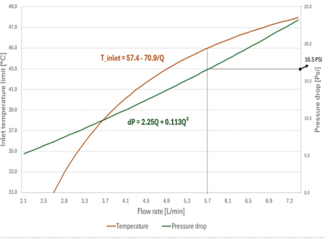
|
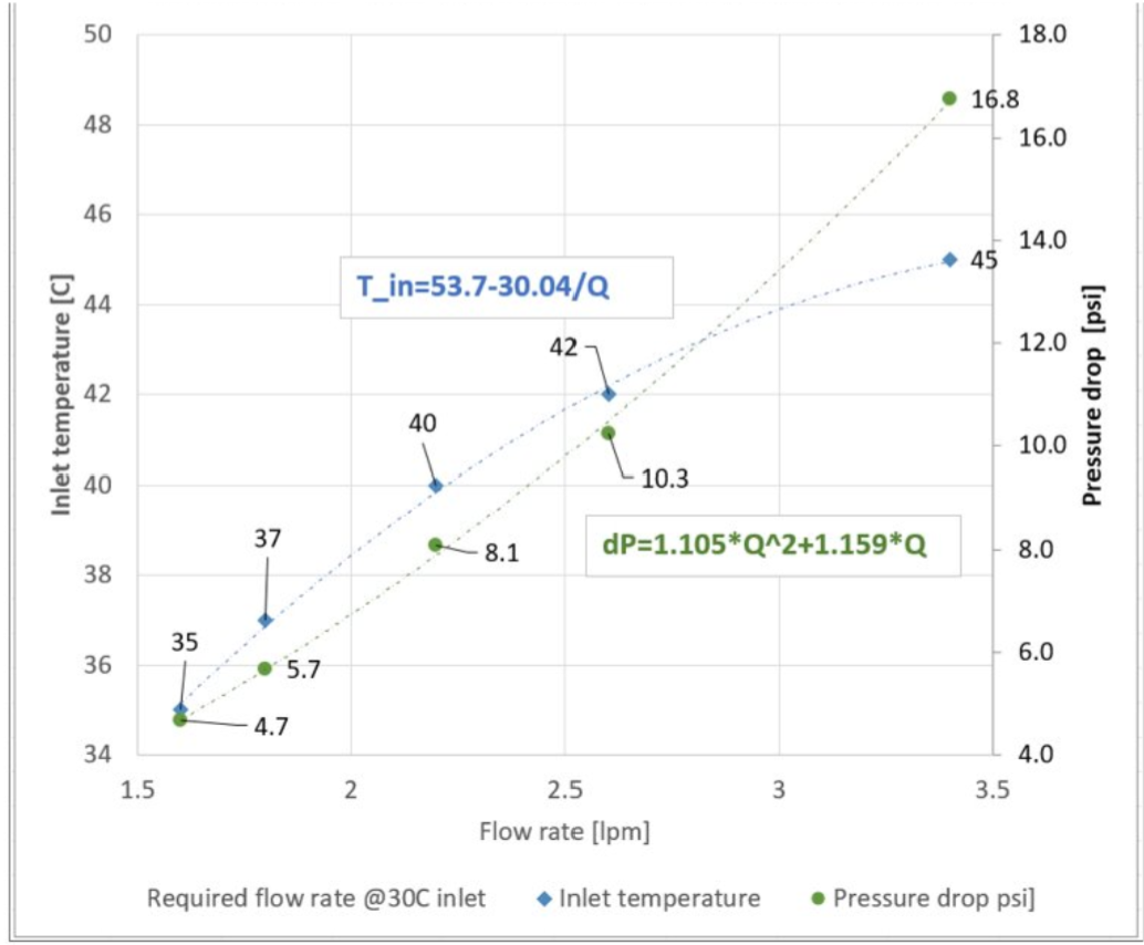
SN6810-LD:
|
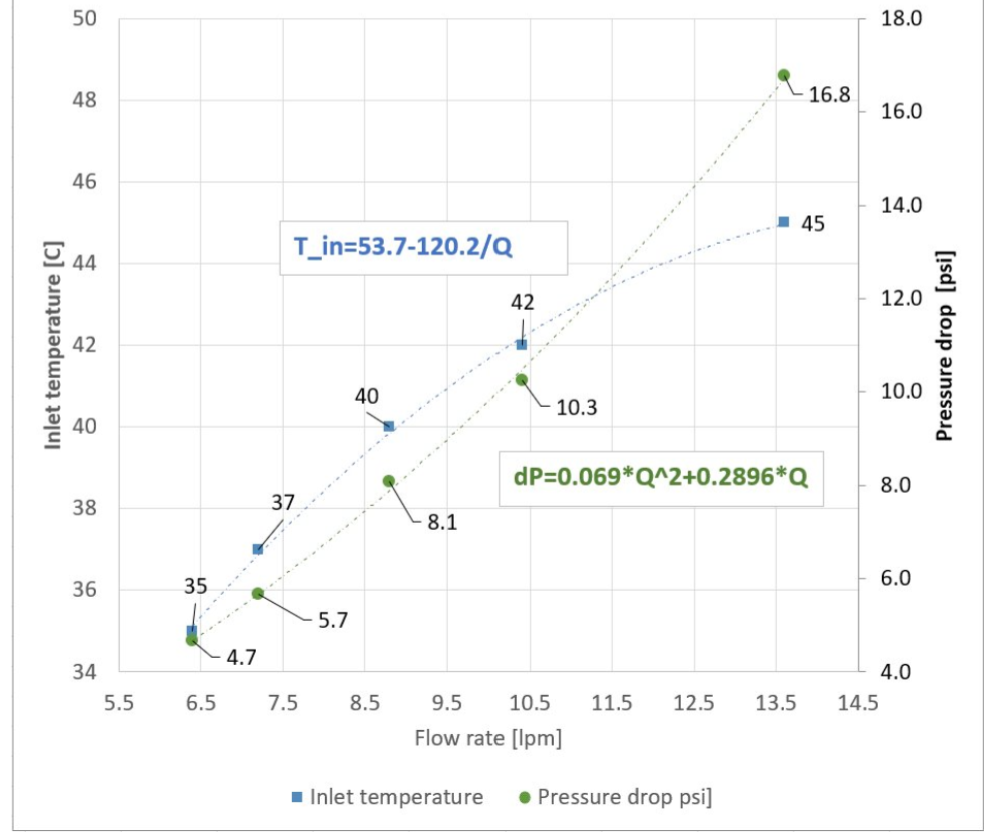
SN6800-LD:
|
Deployment
Inserting the Switch Module (Liquid System Related)
The switch modules are pre-filled with nitrogen in the cooling system, pressurized to at least 1 psi. If the pressure is below 1 psi, perform a "Pressure Hold": refill to 50 psi with N2, wait 12 hours, and verify that the pressure remains above 48 psi to pass. Positive nitrogen pressure prevents humidity or dust ingress.
-
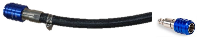
Before insertion, release the gas using the open-ended hose from the maintenance kit.
-
Connect the hose to either of the two FRU hoses to automatically expel the gas.
-
Disconnect the hose once the gas is fully released, then proceed with module insertion.
Failure to fully flood the cooling system with liquid before powering-on may cause significant damage and void the warranty.
Liquid-Cooling System Related Actions
Pressure Check of Nitrogen-Filled Components
Purpose:
-
Confirm that cold plate assemblies, switch trays, and manifolds retain supplier-filled N2 pressure, ensuring no leaks during transit.
Required Hardware:
-
Digital pressure gauge (0–2.1 bar or 0–3.4 bar), data logging.
Process
-
Scan the QR code, log pressure
-
Release the internal pressure
-
Cycle time: <1 minute
Pass/Fail Criteria
-
Must retain ≥1 psi.
-
If the pressure is lower than 1 psi, please perform a "Pressure Hold" test as follows:
-
Refill to 50 psi with N2
-
Wait 12 hours
-
Recheck the pressure. If the pressure is above 48 psi, the unit has passed the test.
-
-
Failures are returned to the supplier.
PG25 Fill
Purpose:
-
To fill assemblies (both individual components and full racks) with 25% propylene glycol, and 75% water solution, ensuring complete fluid coverage and air removal for optimal thermal performance.
Required Hardware:
-
For vacuum fill: Vacuum pump, liquid trap
-
For positive pressure fill: Fill pump
-
25-micron filter on the supply side (for both the component and the rack)
Process
-
Vacuum Fill:
-
Pull vacuum on the assembly from the outlet quick disconnect (QD).
-
Fill the fluid from the inlet QD.
-
Stop filling when the fluid enters the liquid trap.
-
Vacuum specification: 5 kPa or less.
-
-
Positive Pressure Fill:
-
Use a fill pump to introduce coolant.
-
Circulate the fluid back into the reservoir briefly to ensure no bubbles remain.
-
Pass/Fail Criteria
-
Fluid reservoir weight can optionally be measured before and after filling as a quality check.
Caveats:
-
If using a positive pressure pump with circulation, ensure a 25-micron filter is installed on the supply side.
-
If the assembly is complex with multiple fluidic elevations or high points, vacuum filling is preferred.
-
Expected Cycle Time: 2–3 minutes.
Last updated: