System Installation and Initialization
Pay close attention to the mechanical, power, and thermal precautions for rack-mounted equipment during the installation and initialization processes.
The rack mounting holes conform to the EIA-310 standard for 19-inch racks. Take precautions to guarantee proper ventilation so that the system maintains sufficient airflow at ambient temperature.
Unless otherwise specified, NVIDIA products are designed to work in an environmentally controlled data center with low levels of gaseous and dust (particulate) contamination. The operation environment should meet severity level G1 as per ISA 71.04 for gaseous contamination and ISO 14644-1 class 8 for cleanliness level.
The installation procedure for the system involves the following steps:
-
Review the safety warnings.
-
Review the airflow directions for the system and rack.
-
Make sure that the package contents are not missing or damaged.
-
Mount the system into a rack enclosure.
-
Perform a system bring-up.
-
(Optional) FRU replacements.
Airflow
This section applies to the SN6600 systems only. All other systems in this series are cooled by a liquid cooling mechanism. For further information, see Liquid Cooling Specifications.
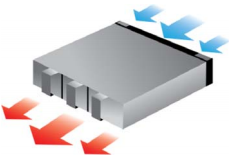
The SN6600 systems are offered with connector-side inlet to power-side outlet airflow.
All servers and systems in the same rack should have the same airflow direction. Likewise, all FRU components must also have the same airflow direction. A mismatch in the airflow will affect the heat dissipation.
The table below provides an airflow color legend:
|
Direction |
Description |
|---|---|
|
|
Connector side inlet to power side outlet. The arrows indicate the flow of air from the connector-side inlet to the power-side outlet. |
Package Contents
Before installing your new system, unpack it and make sure all parts are included and undamaged. If anything is missing or damaged, contact networking-support@nvidia.com.
The packages include:
|
SN6600 |
SN6600-LD/SN6800-LD/SN6810-LD |
|---|---|
Power cords and cable retainers are not included in this package, and can be ordered separately. |
|
If the product is supplied with dust caps, do not remove them until installation is required. Keep dust caps installed on all unused ports to prevent foreign object contamination of the cage and to avoid thermal air-pressure leakage.
Mounting Options
For installation instructions, refer to the following table:
|
System Model |
Rail Kit |
|---|---|
|
SN6600/SN6600-LD/SN6800-LD |
SN6600/SN6600-LD/SN6800-LD Rail Kit |
|
SN6810-LD |
SN6800-LD Rail Kit |
Last updated: