Introduction
This chapter provides an overview and prerequisites for installing Single-Mode and Multi-Mode transceivers, Optical Fibers and Active Copper Cables. The new 200G/400/800G Ethernet interconnects make extensive use of pluggable optical transceivers and detachable optical fibers for easier installation, inspection and debugging.
For more information on best practices and recommendations to ensure best performance of our cables, refer to NVIDIA Cable Management Guidelines.
Form Factor
NVIDIA's products utilize different type of ports:
|
Form Factor |
Description |
Spectrum-6 Usage |
|---|---|---|
|
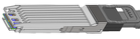
OSFP - Octal Small Form-factor Pluggable |
Connected to the ASIC with 8 electrical lanes. |
The usage of the lanes enables to set versatile ports speeds, for instance an 800G port can be configured as 4 lanes of 200G or 8 lanes of 100G. |
|
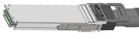
QSFP - Quad Small Form-factor Pluggable |
Connected to the ASIC with 4 electrical lanes. |
Spectrum-6 switches' QSFP112 utilizes 2 electrical lanes only to provide 2 discrete 100G general-purpose ports. |
|
SFP28 - Small Form-factor Pluggable |
Utilizes 1 electrical lane to the ASIC. |
Spectrum-6 switches may include a few SFP28 general purpose ports, supporting 25G speed. |
Optical Transceiver Types
Internal Electronics
|
Type |
Description |
|---|---|
|
FRO - Full Retimed Optics |
Employs DSP ICs on both transmit and receive paths |
|
TRO - Transmit only Retimed Optics |
Utilizes DSP ICs in transmit only |
Transceiver Cooling
|
Type |
Usage |
|---|---|
|
Integrated Heat Sink
|
Used in air cooled switches in OSFP form-factor. |
|
Riding Heat Sink
|
Used in liquid cool switches as well as server-side in OSFP and QSFP-112 form-factors. |
Fibre Optic Cable Assemblies
Structured cabling eases servicing of the optical transceivers in the data center as transceivers are detachable from the cable. This also allows easier installation since there are no ESD sensitive or bulky transceivers involved in the cabling.
Patch panels and trunk cables add further flexibility to the infrastructure. Pluggable optical cables require special installation and cleaning procedures to avoid mishandling and bricking these products.
The maximum reach specifications of NVIDIA 400/800G Ethernet transceivers assume two optical connector junctions or patch panels in the link, a total of 4 ferule-to ferule connections.
|
Type |
Description |
|---|---|
|
MPO-12/APC: Multiple Push-On 12-fiber, Angled Polished Connector |
|
|
MPO-12/UPC: Multiple Push-On 12-fiber, Ultra Flat Polished Connector |
|
MPO-12/APC and MPO-12/UPC are not compatible.
Optical Fibers Options
|
Type |
Length |
|---|---|
|
MPO Single-Mode straight cables |
Total length up to 500m (inc. patch panels, trunk and cables). |
|
MPO Single-Mode splitter cables |
Total length up to 50m (inc. patch panels, trunk, and cables). |
|
MMC Single-Mode straight cables |
Total length up to 500m (inc. patch panels, trunk and cables). |
|
LC Single-Mode straight cables |
Total Lengths of 2km (FR4), 6km/10km (LR4) (inc. patch panels, trunk and cables). |
Patch Panels
Patch panels have multiple ports that connect multiple devices together and help organize cables as well as introduce shuffling between end-points Servers to Leaves/Leaves to Spines.
Active Copper Cables Assemblies
|
Type |
Description |
|---|---|
|
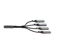
LACC: Linear Active Copper Cables |
The cables use built-in linear equalizer and amplifiers to extend the reachability. The LACC cables support OSFP to 4xOSFP (twin 800G to 4x400G) and OSFP to 2xOSFP (twin 800G to 2x800G) breakouts. |
|
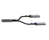
ACC: Active Electric Copper Cables |
The cables use DSPs on each end-point. RHS to RHS and IHS to IHS versions of this cable are available, providing a direct connectivity of twin 800G ports. |

Cable Orientation
SN6600:
SN6600-LD:
Splitting Options
SN6810-LD, SN6600-LD, and SN6600 systems, all ports support splitting according to the following configurations:
|
Port Speed |
Split |
Logical Ports |
Lane Speed |
Signaling |
|---|---|---|---|---|
|
800GbE |
N |
128 |
4×224G |
PAM4 |
|
400GbE |
Y |
256 |
2×224G |
PAM4 |
|
400GbE |
Y |
128 |
4×112G |
PAM4 |
|
200GbE |
Y |
512 |
1×224G |
PAM4 |
|
200GbE |
Y |
256 |
2×112G |
PAM4 |
|
100GbE |
Y |
512+2 |
1×112G |
PAM4 |
SN6800-LD Support the following port speeds configurations:
|
Port Speed |
Split |
Logical Ports |
Lane Speed |
Signaling |
|---|---|---|---|---|
|
200GbE |
N |
2048 |
2x224G |
PAM4 |
|
100GbE |
N |
2048+8 |
1×112G |
PAM4 |
The SN6800 system does not support additional port breakout modes.
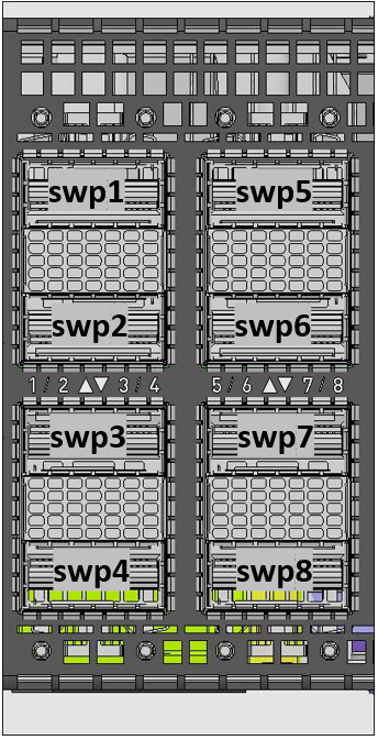
Connector Numbering in a Belly-to-Belly Configuration
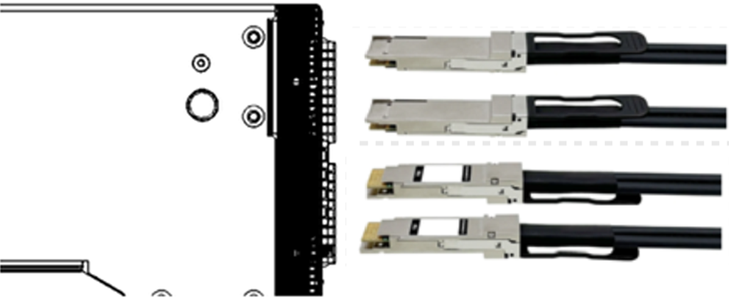
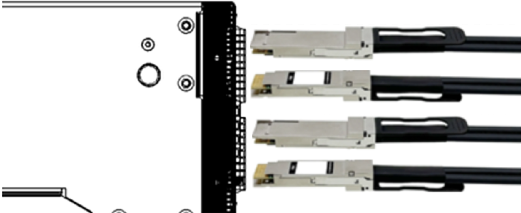
SN6600-LD and SN6600 systems use OSFP cages.
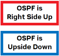
The OSFP-based optical transceivers have two distinctive ports that can be used as OSFP transceivers inserted to the switch in a "belly-to-belly" configuration, meaning that the transceiver on the top will be right side up, and the transceiver below it will be upside down.
The following illustration depicts the numbering of the ports:
|
|
Connector: Twin 800G Port: |
|
|
Port Configuration |
Physical Connector |
NOS Description |
Examples |
|---|---|---|---|
|
800G |
C1 |
swp |
swp1, swp2 |
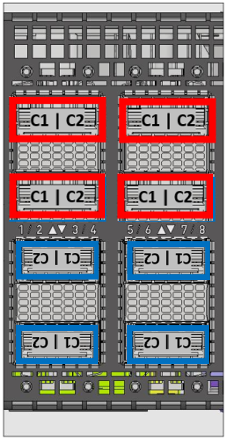
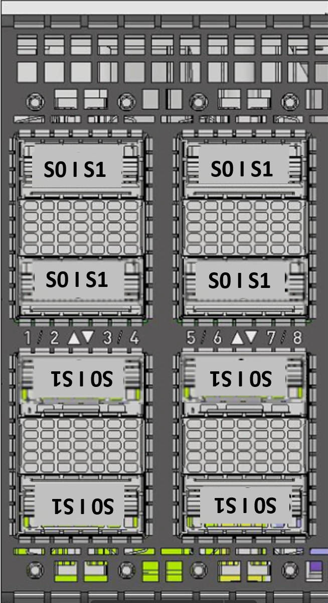
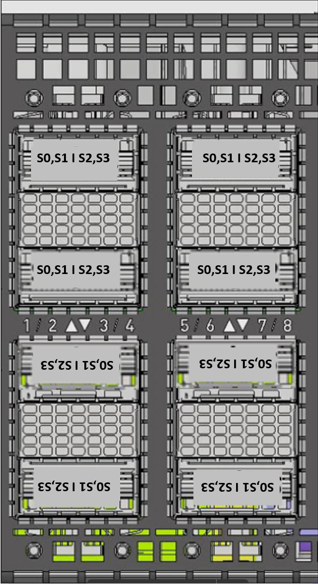
Breakout Ports Reflection in NOS
The illustration below shows the first two rows of the system’s OSFP carriers: the image on the left identifies the OSFP cage number as it is presented by the OS; the image on the right identifies the corresponding subinterfaces.
|
Connector #
|
Connector #
|
|---|---|
|
|
|
|
Port Configuration |
Physical Connector |
Sub-interface |
Examples |
|---|---|---|---|
|
2×800G |
C1 |
S0 |
swp1s0, swp24s0 |
|
C2 |
S1 |
swp1s1, swp64s1 |
|
|
4×400G |
C1 |
S0, S1 |
swp2s0, swp2s1 |
|
C2 |
S2, S3 |
swp8s2, swp8s3 |
|
|
8×200G |
C1 |
S0, S1, S2, S3 |
swp60s0, swp60s1, swp60s2, swp60s3 |
|
C2 |
S4, S5, S6, S7 |
swp55s4, swp55s5, swp55s6, swp55s7 |
For additional Information on NVIDIA Interconnect Solution, please refer to: https://docs.nvidia.com/networking/interconnect/index.html.
Last updated: