

A vertical stepper wizard that walks administrators through cluster setup before validation. Completed steps are marked with a checkmark; steps can be visited in any order. Skip to Validation jumps directly to the final step from any earlier step.
When a topology is loaded, metadata (file name, server path, last updated time) appears above the stepper, with download links for the topology and DC layout files.
Step 1 — Load Topology
Load the fabric topology that defines the devices CVT will manage.
-
Load modes: P2P (all fabric types), TOPO (IB fabrics), DOT (ETH fabric), and UFM (when running embedded in UFM).
-
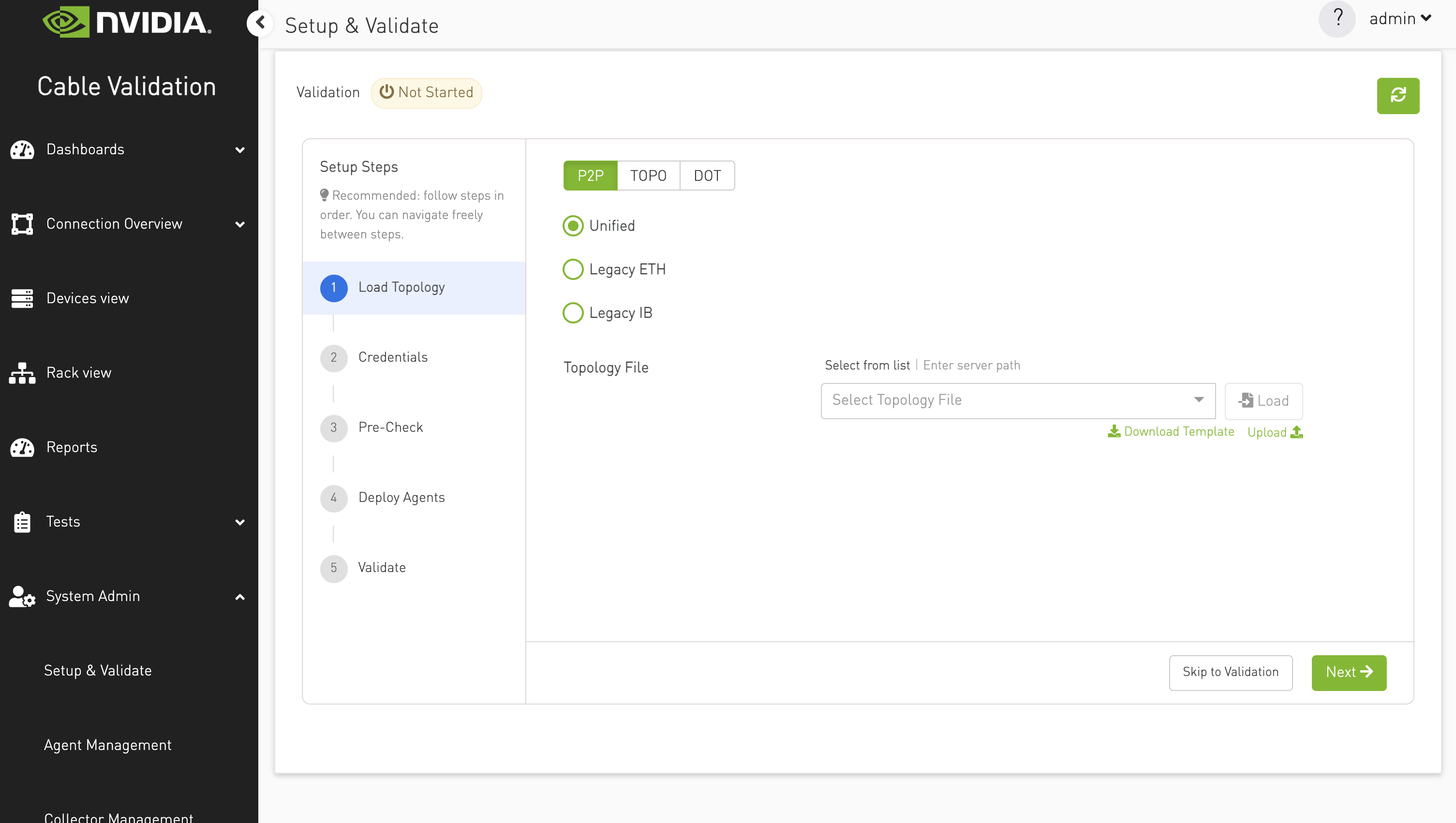
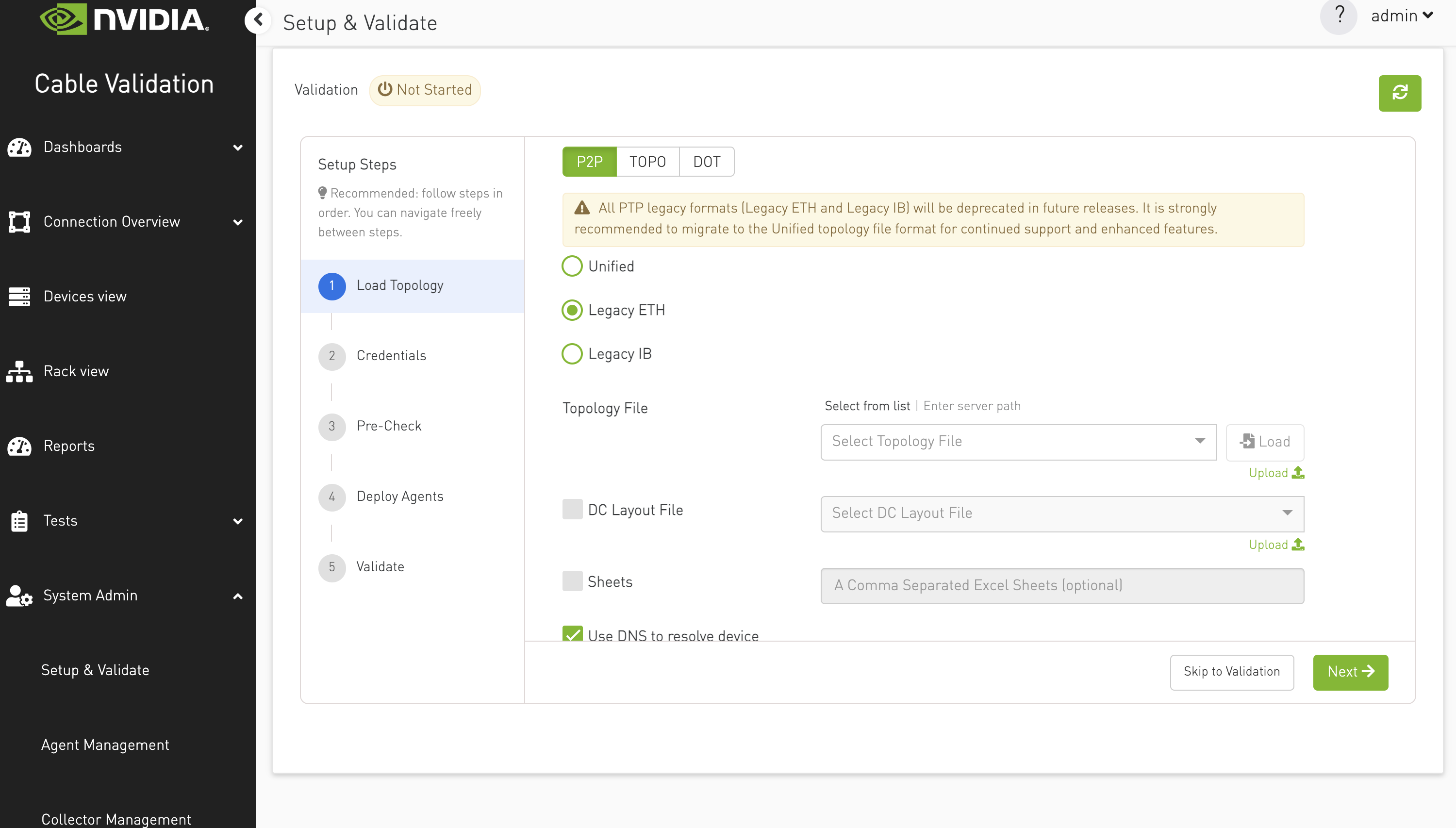
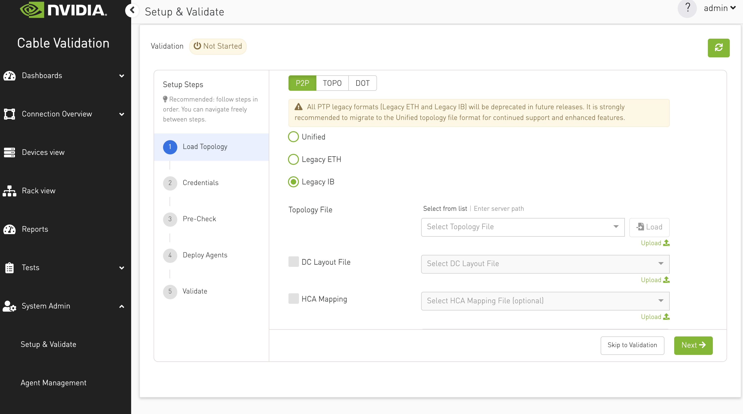
P2P formats: Unified (recommended), Legacy ETH, Legacy IB. Legacy formats show a deprecation warning.
-
File source: Select from an uploaded file list, or enter an absolute server path.
-
Additional files: DC layout file, IP mapping file (where applicable).
-
Constraints: Loading a new topology is blocked while validation is running. A warning banner is shown if validation is active.
P2P File
Users must provide the following inputs:
-
Format: PTP file format, which can be one of the following:
-
Unified: It accepts various cluster types, including InfiniBand, Ethernet, and NVLink. For more information, please visit [Unified Topology Format](P2P File Topology Format).
-
-
-
Legacy ETH: It accepts only Ethernet fabric. For more information, please visit PTP ETH.
-
-
-
Legacy IB: It accepts only InfiniBand fabric. For more information, please visit PTP IB.
-
-
Topology File:
-
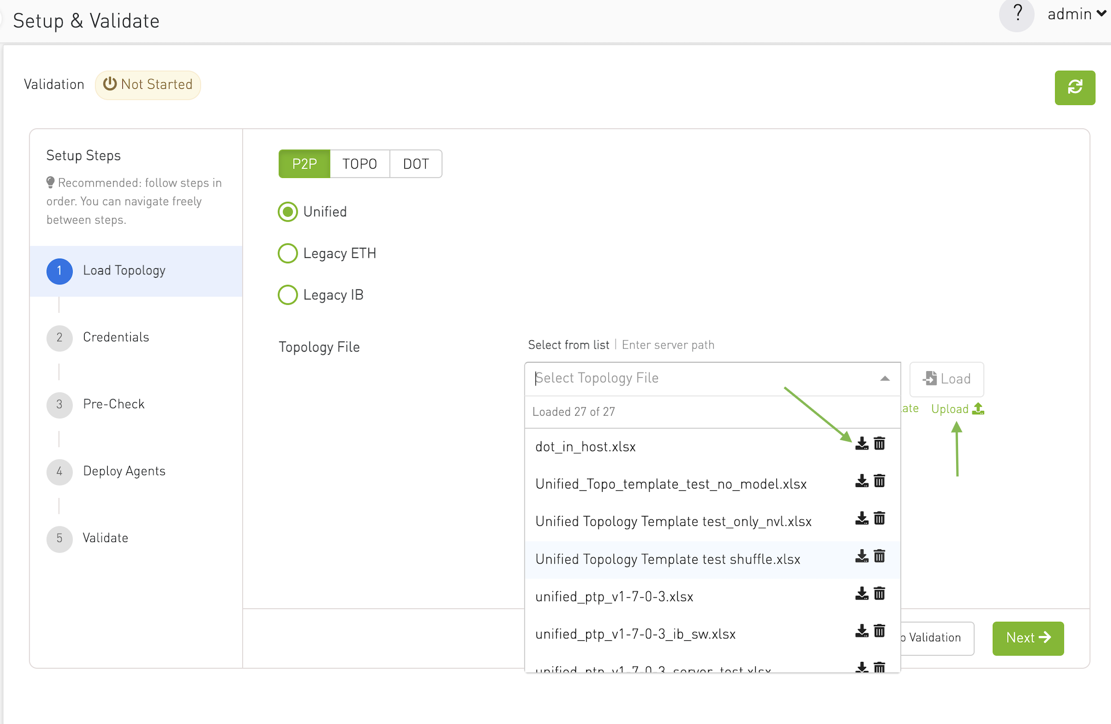
Allows users to select or upload a PTP file.
-
Files can be chosen from a dropdown menu listing all .xlsx files in the directory: /opt/bringup_data/data/uploads/topology/ptp/
-
This directory is a shared volume linked to:/cable_bringup_root/data/uploads/topology/ptp/
-
Users can also upload a file directly from their computer using the Upload button below the load button.
-
Additionally, users can download any file from the dropdown to their local computer.
-
For the Unified type, users can download a template file that serves as a guide for creating their own unified P2P file.
-
-
DC Layout File (Optional, Appears Only with Legacy formats):
-
Used for selecting or uploading a data center floor layout file.
-
Files can be chosen from a dropdown menu listing all .csv files in the directory: /opt/bringup_data/data/uploads/topology/dc_layout/
-
This directory is a shared volume linked to: /cable_bringup_root/data/uploads/topology/dc_layout/
-
Users can upload a file directly from their computer using the Upload button.
-
Users can enable the DC Layout field by selecting the HCA Mapping checkbox.
-
-
HCA Mapping (Optional, Appears Only with Legacy formats):
-
Allows users to select or upload an HCA mapping file.
-
Files can be chosen from a dropdown menu listing all .csv files in the directory:/opt/bringup_data/data/uploads/topology/hca_mapping/
-
This directory is a shared volume linked to:
/cable_bringup_root/data/uploads/topology/hca_mapping/ -
Users can enable the HCA Mapping field by selecting the HCA Mapping checkbox.
-
-
Sheets (Optional, Appears Only with Legacy formats): The user can specify sheets to be included in the file by enabling the Sheets input field (via checkbox) and entering the sheet names as comma-separated values.
-
Use DNS to resolve device names (Appears Only with Legacy formats): This option is selected by default. When deselected, an additional input field appears where users can upload an IP file.
In this mode, the Load Topology process runs two commands sequentially — Load Topology and Load IP — to load both topology and IP data correctly.
-
Allow CVT to manage agents on servers (Appears Only with Unified and Legacy ETH formats): This option is deselected by default. If selected, CVT manages the servers included in the topology file; otherwise, it manages only the switches and ignores the servers.
Topo File
User must provide the following input:
-
Topology File:
-
Allows users to select or upload a .topo file.
-
Files can be chosen from a dropdown menu listing all .topo files in the directory:/opt/bringup_data/data/uploads/topology/topo/
-
This directory is a shared volume linked to:/cable_bringup_root/data/uploads/topology/topo/
-
Users can upload a file directly from their computer using the Upload button.
-
Additionally, users can download any file from the dropdown to their local computer.
-
-
Use DNS to resolve device names: This option is selected by default. When deselected, an additional input field appears where users can upload an IP file.
In this mode, the Load Topology process runs two commands sequentially — Load Topology and Load IP — to load both topology and IP data correctly.
Dot File
-
Topology File:
-
Allows users to select or upload a .dot file.
-
Files can be chosen from a dropdown menu listing all .topo files in the directory: /opt/bringup_data/data/uploads/topology/dot/
-
This directory is a shared volume linked to :/cable_bringup_root/data/uploads/topology/dot/
-
Users can upload a file directly from their computer using the Upload button.
-
Additionally, users can download any file from the dropdown to their local computer.
-
-
Use DNS to resolve device names: This option is selected by default. When deselected, an additional input field appears where users can upload an IP file.
In this mode, the Load Topology process runs two commands sequentially — Load Topology and Load IP — to load both topology and IP data correctly.
-
Allow CVT to manage agents on servers: This option is deselected by default. If selected, CVT manages the servers included in the topology file; otherwise, it manages only the switches and ignores the servers.
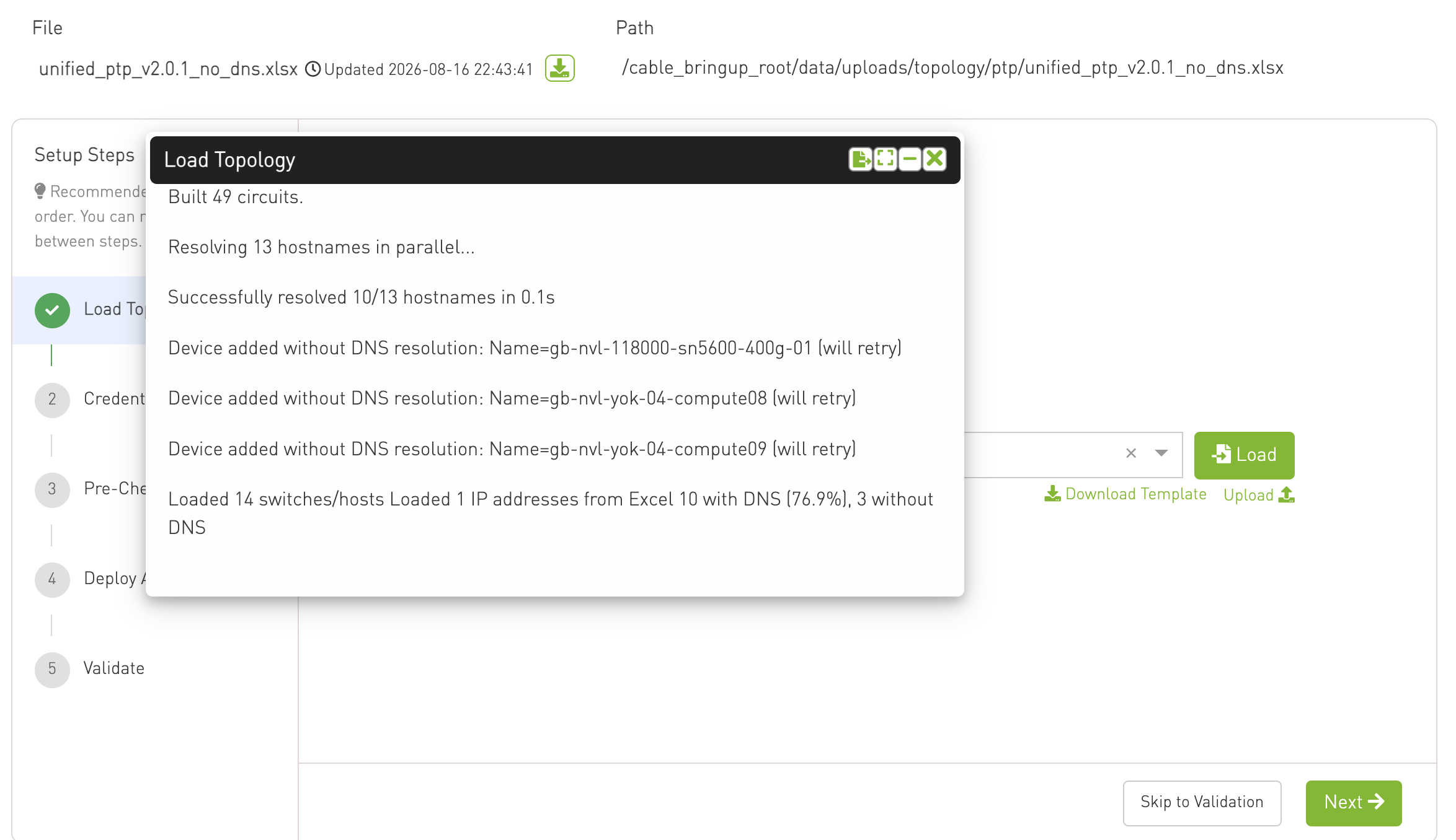
Topology Summary
After clicking on Load, the topology file is loaded and this step provides a summary of the loaded topology.
Users can review the details to confirm that the correct file and settings have been applied.
The topology summary can be exported as a text file, allowing users to save, share, or reference the information later.
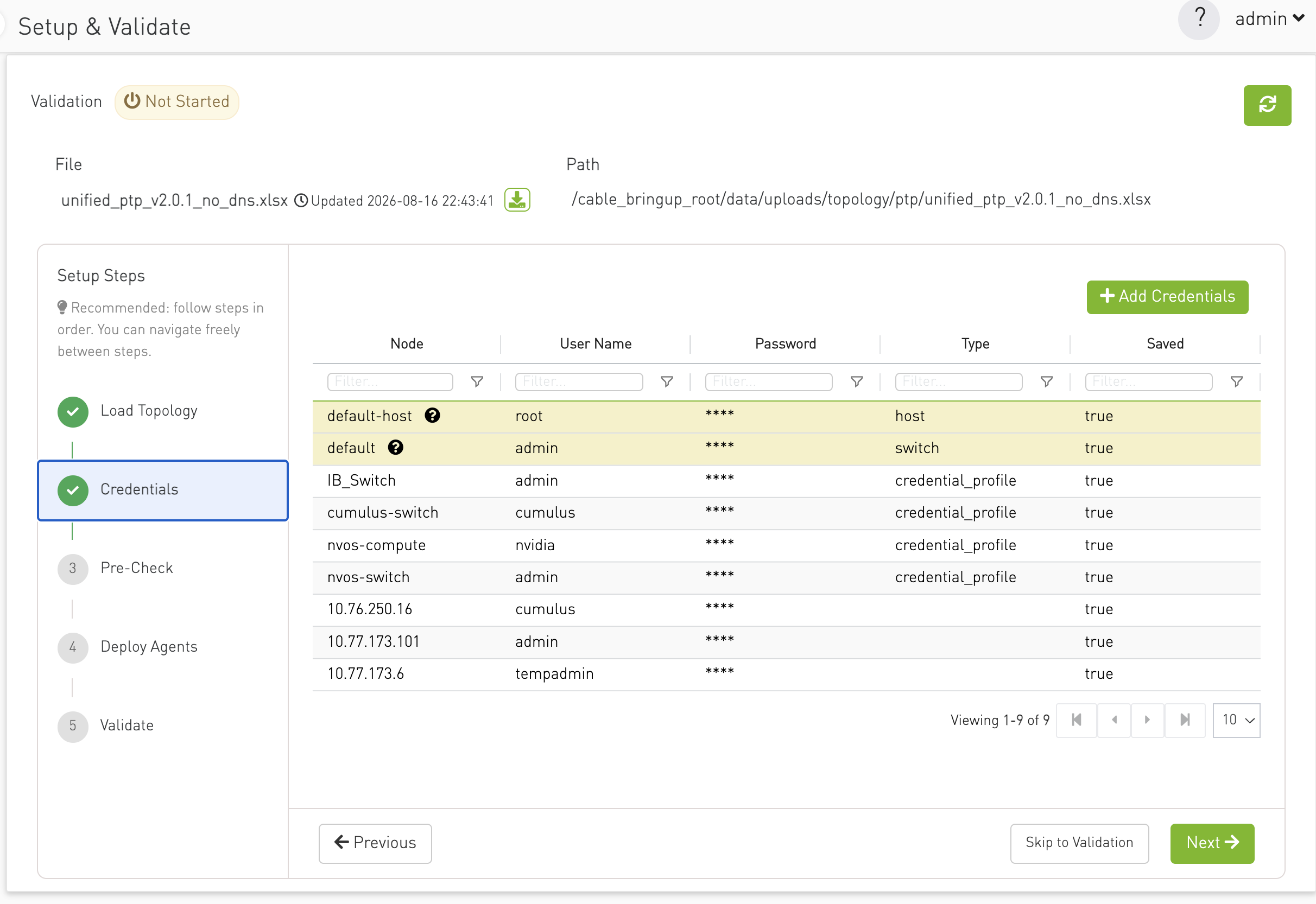
Step 2 — Credentials
Manage node credentials required for agent deployment and device access. Uses the shared nodes-credentials table component. Credentials must be configured before pre-check and deploy steps can succeed.
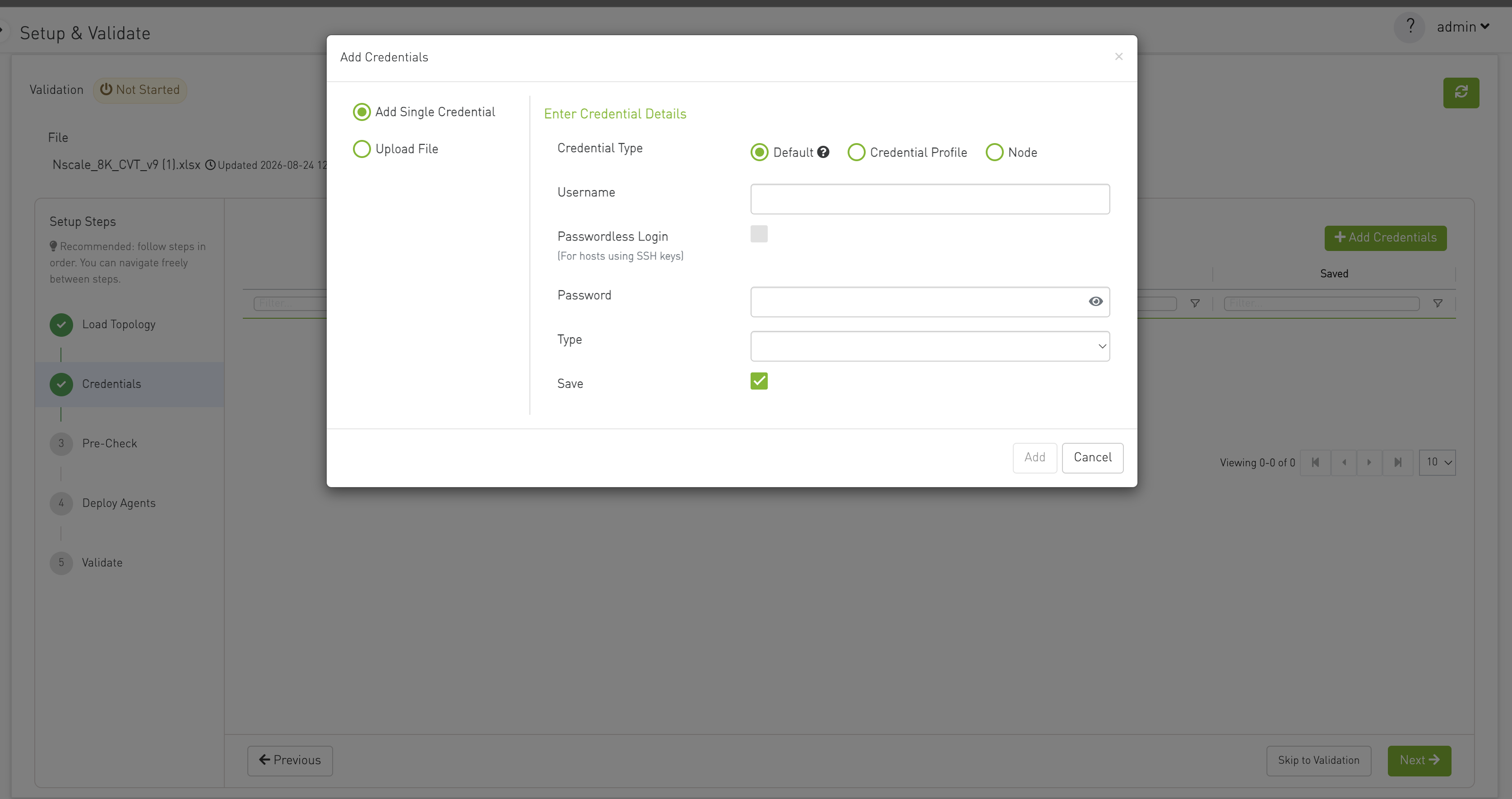
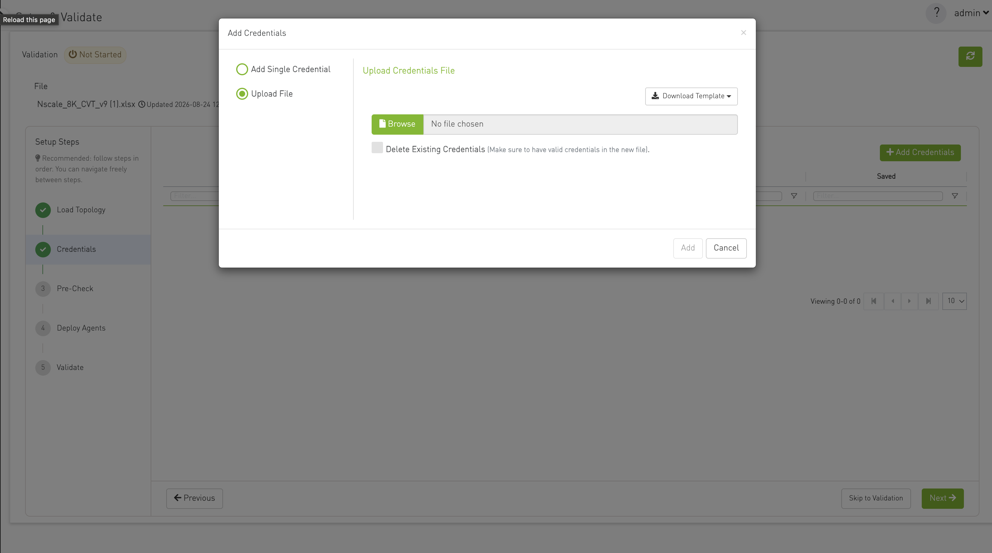
For more information, please visit Device Access Credentials
Step 3 — Pre-Check
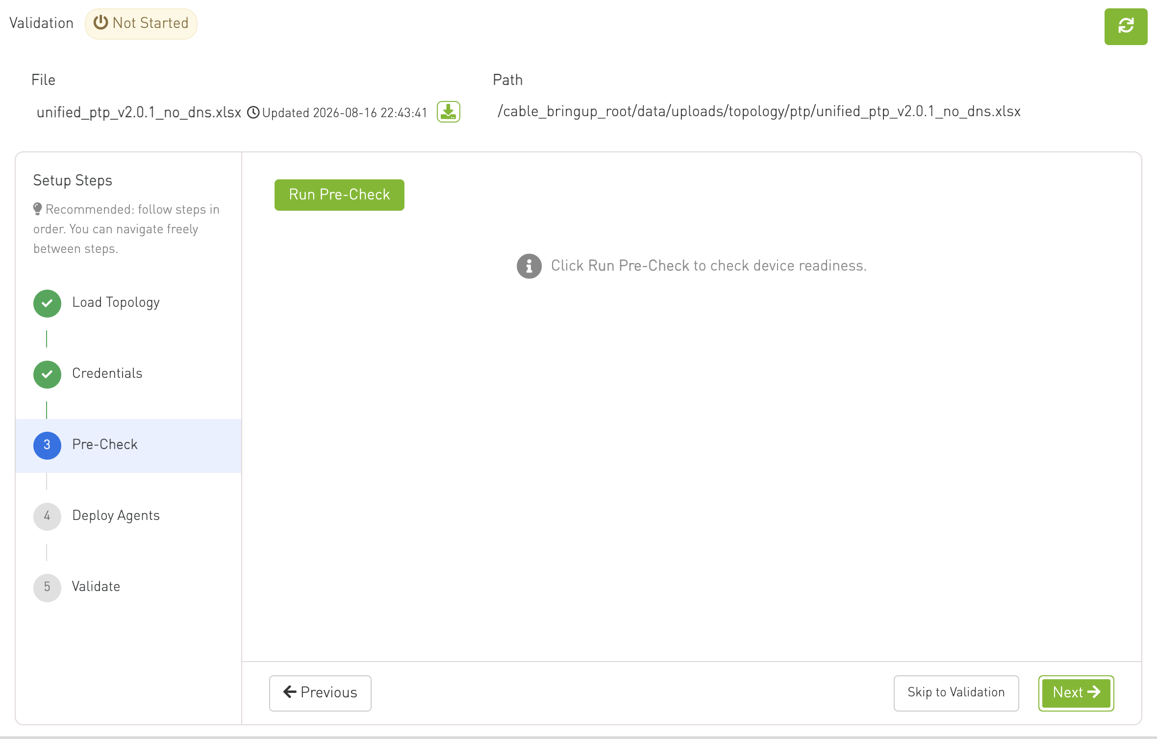
Run readiness checks across all devices.
-
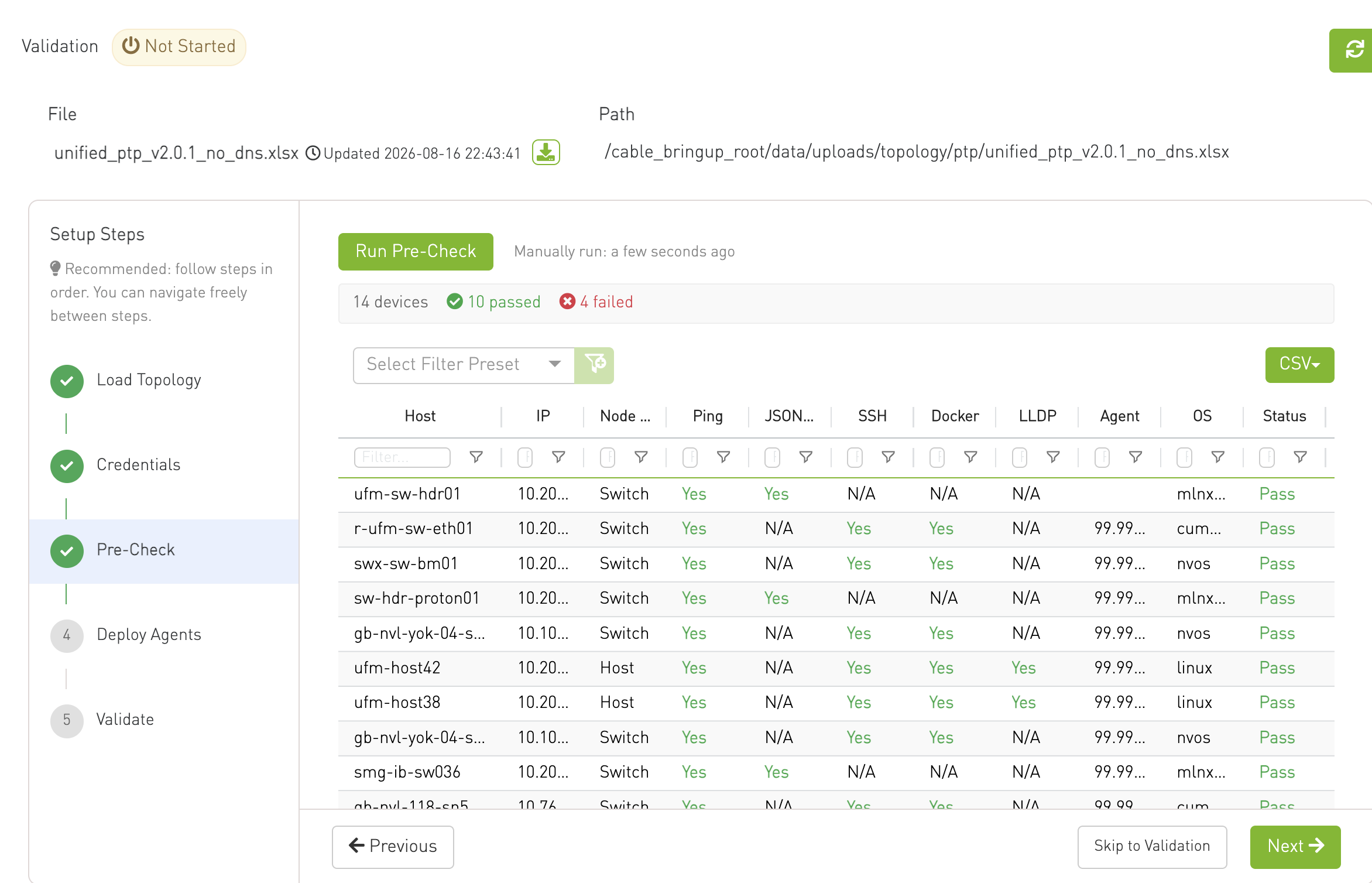
Checks performed: Ping, JSON API, SSH, Docker, LLDP, and agent status.
-
Run Pre-Check starts the check; results poll until complete. A last-run timestamp indicates result freshness.
-
Results: Summary bar (total / passed / failed) and a per-device results grid with pass/fail per check.
Pre-check results:
Step 4 — Deploy Agents
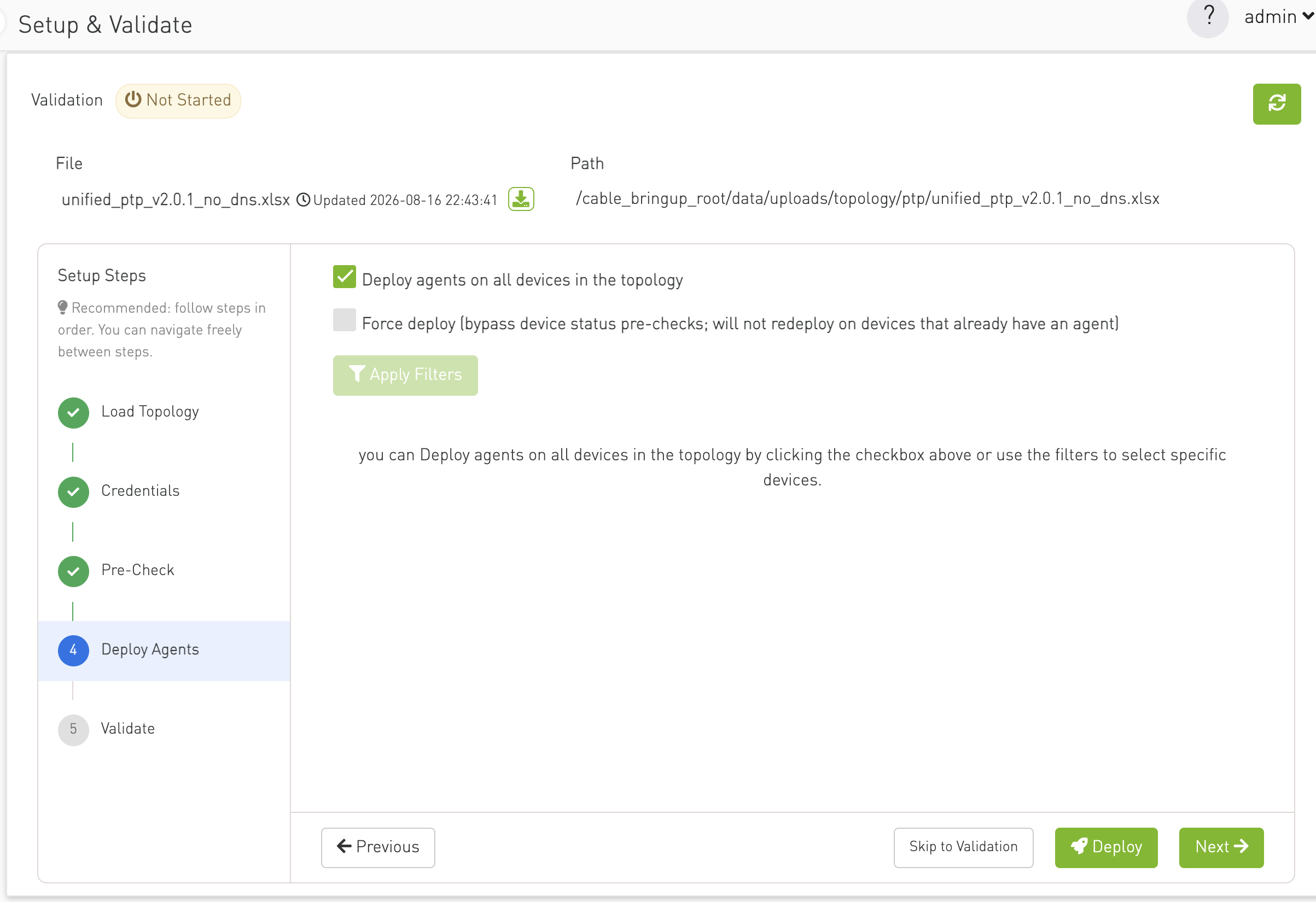
Deploy or remove CVT agents on selected devices.
-
Shows the deploy-agents component with scope context (mode, workspace, deployment, scoped device count).
-
Deploy button in the step navigation runs deployment on the current selection.
-
Deploy is disabled while validation is running or while a deploy is in progress.
-
Agent command output is shown via the standard command polling window.
Step 5 — Validate
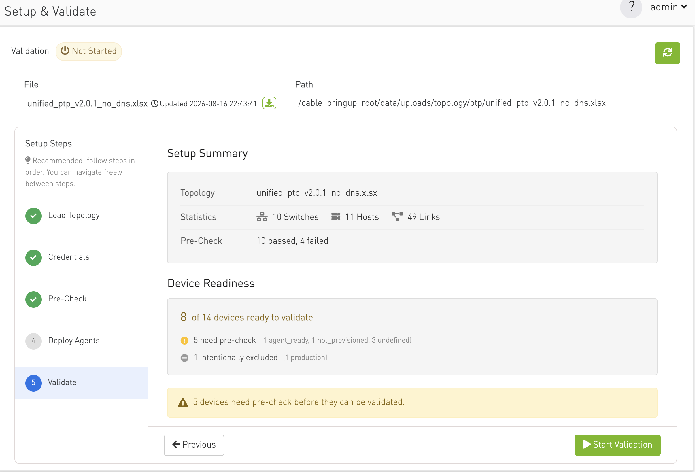
Review setup readiness and start or stop validation.
-
Setup Summary: Topology file name, switch/host/link counts, scope label (if enabled), and pre-check summary.
-
Device Readiness: Count of devices ready to validate vs. total, with breakdowns for devices needing pre-check or intentionally excluded.
-
Alerts: Warning or error banners when readiness is incomplete.
-
Start Validation / Stop Validation buttons in the step navigation (same behavior as Service Controls).
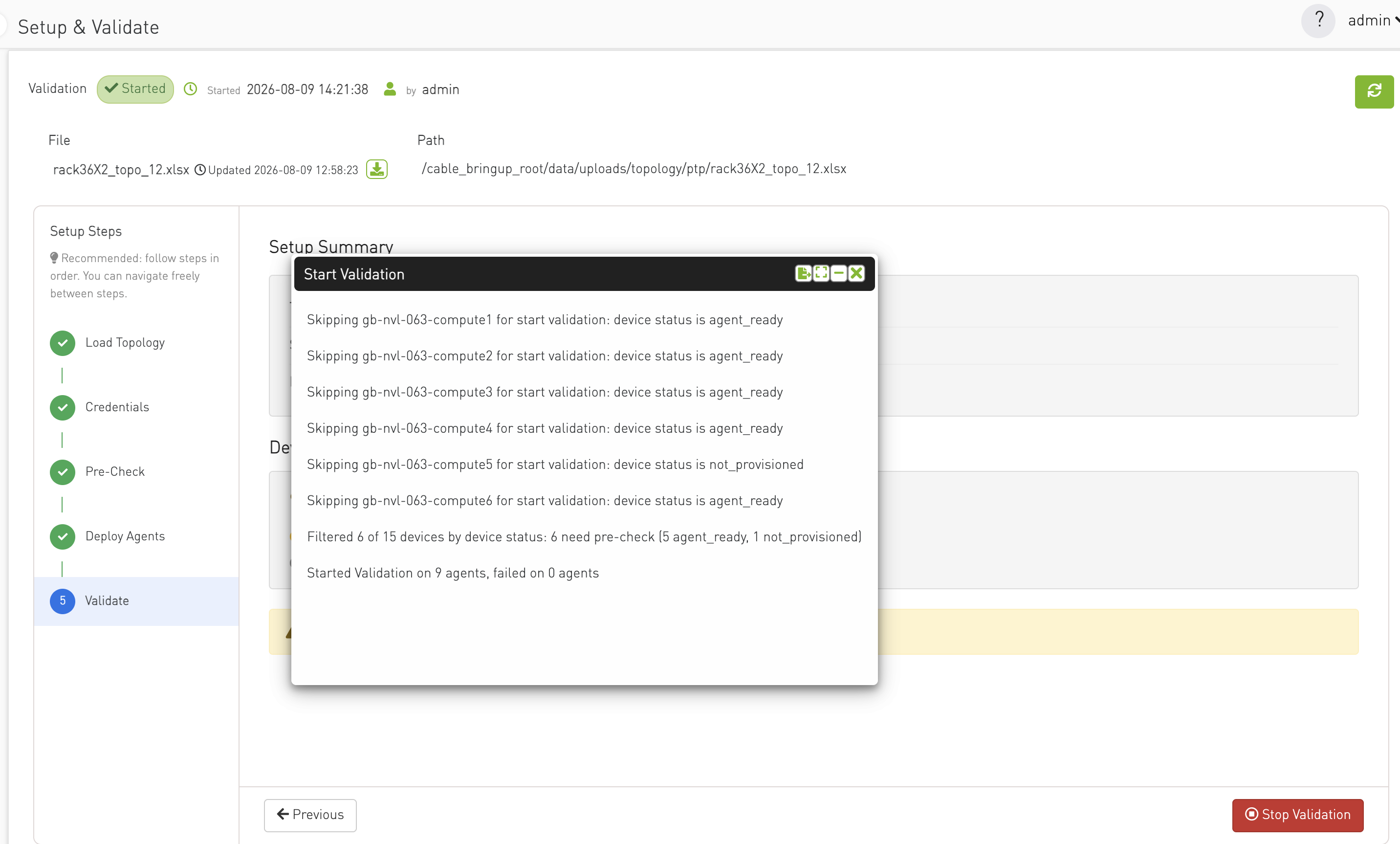
When the user clicks Start Validation, a pop-up window appears, providing real-time visibility into the validation progress and results. Users can minimize this window and continue navigating within the application while the validation runs in the background.
The validation output can be exported as a text file for later review, troubleshooting, or documentation purposes.
During the validation process, the Close button is disabled to prevent accidental closure until the validation results are ready for review.
Last updated: